Pioneer VSX-517-S Service Manual
Audio/video multi-channel receiver
Hide thumbs
Also See for VSX-517-S:
- Operating instructions manual (63 pages) ,
- Operating instructions manual (78 pages) ,
- Specification sheet (2 pages)
Table of Contents
Advertisement
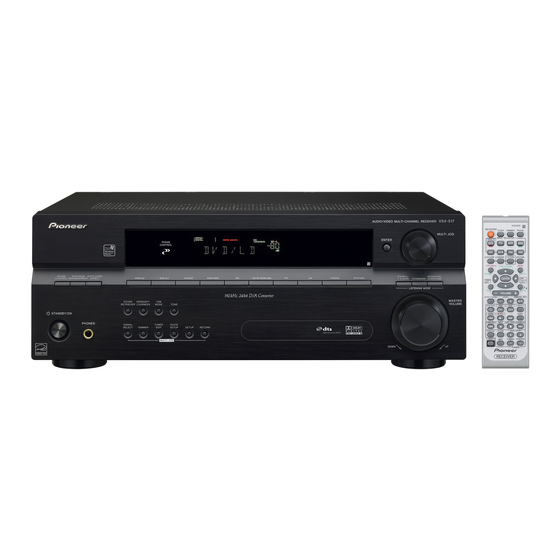
AUDIO/VIDEO MULTI-CHANNEL RECEIVER
VSX-517-K
VSX-517-S
THIS MANUAL IS APPLICABLE TO THE FOLLOWINGMODEL(S) AND TYPE(S).
Model
Type
VSX-517-K
KUCXJ
VSX-517-S
KUCXJ
For details, refer to "Important Check Points for Good Servicing".
PIONEER CORPORATION
PIONEER ELECTRONICS (USA) INC. P.O. Box 1760, Long Beach, CA 90801-1760, U.S.A.
PIONEER EUROPE NV Haven 1087, Keetberglaan 1, 9120 Melsele, Belgium
PIONEER ELECTRONICS ASIACENTRE PTE. LTD. 253 Alexandra Road, #04-01, Singapore 159936
PIONEER CORPORATION 2007
PHASE
DIALOGUE
AUTO SURR/
CONTROL
ENHANCEMENT
STANDBY / ON
PHONES
Power Requirement
AC 120 V
AC 120 V
4-1, Meguro 1-chome, Meguro-ku, Tokyo 153-8654, Japan
ENTER
PHASE
CONTROL
STEREO/
DIRECT
DVD/LD
DVD 5.1
TV /SAT
DVR/ VCR
CD
CD-R / TAPE / MD
FM
AM
TUNING
STATION
F.S.SURR
SOUND
MIDNIGHT/
VSB
RETRIEVER
LOUDNESS
MODE
TONE
SIGNAL
TUNER
QUICK
SELECT
DIMMER
EDIT
SETUP
SETUP
RETURN
MULTI JOG
DO
VSX-517-K
VSX-517
MULTI JOG
ADVANCED
STANDARD
SURROUND
LISTENING MODE
MASTER
VOLUME
ORDER NO.
UP
RRV3550
Remarks
T-ZZK FEB. 2007 printed in Japan
Advertisement
Table of Contents

Related Manuals for Pioneer VSX-517-S


Summarization of Contents
Safety Information
Manual Audience and Disclaimer
Manual is for qualified technicians; improper repairs can affect safety and void warranty.
Product Safety Warning: Hazardous Substances
Product contains lead in solder and chemicals known to cause cancer or birth defects.
Safety Precautions
Includes leakage current check and general product safety notices.
Leakage Current Check Procedure
Measure leakage current to earth ground; must not exceed 0.5 mA.
Product Safety Notice
Many parts have special safety characteristics; use specified replacement parts to avoid hazards.
Important Check Points for Good Servicing
Product Safety in Servicing
Ensures safety during repairs: use genuine parts, avoid mods, ensure proper soldering.
Use Specified and Genuine Parts
Use specified parts for repair, ensuring genuine parts are used for safety.
Inspect Power Cord Condition
Check power cord coating for damage (wires, scratches, melting); exchange if damaged.
Maintain Safe Servicing Environment
Pay attention to surroundings (static electricity, furniture) to prevent injuries during repairs.
Product Adjustments
Perform optimum adjustments to maintain original performance as per manual instructions.
Cleaning Procedures
Properly clean parts like optical pickups, tape heads, and lenses to restore performance.
Specifications
Amplifier Specifications
Details continuous and rated power output, sensitivity, impedance, and tone control for the amplifier.
Audio Section Specifications
Details frequency response, signal-to-noise ratio, and output levels for the audio inputs/outputs.
Video Section Specifications
Details input sensitivity, impedance, output level, impedance, and frequency response for video signals.
Component Video Specifications
Details input sensitivity, impedance, output level, impedance, and frequency response for component video.
FM Tuner Specifications
Details frequency range, usable sensitivity, quieting sensitivity, signal-to-noise, selectivity, and separation.
Furnished Parts List
Lists the parts supplied with the unit, such as antennas, batteries, and remote control.
Exploded Views and Parts List
Parts List Notes
Notes on unavailable parts (NSP) and the safety factor mark ( ).
Packing Section Parts List
List of parts included in the packing section with Mark No. and Part No.
Exterior Section Parts List
List of external parts with Mark No., Description, and Part No.
Front Panel Section Parts List
List of front panel parts with Mark No., Description, and Part No.
Block and Schematic Diagrams
Block Diagram
Provides a high-level overview of the unit's functional blocks and signal flow.
Overall Wiring Connection Diagram
Illustrates the wiring connections between various assemblies and connectors.
Main Assy (1/3)
Detailed schematic diagram for the Main Assembly, part 1 of 3.
DSP Assy (1/2)
Detailed schematic diagram for the DSP Assembly, part 1 of 2.
Power Pack & Trans Assy Diagrams
Schematics for Power Pack Assy (1/2) and Trans2/Trans3 Assys.
DSP Block Diagram
Block diagram illustrating the DSP Assy functionality and connections.
PCB Connection Diagrams
Digital Input Assy PCB
PCB connection diagram for the Digital Input Assembly.
Main Assy PCB
PCB connection diagram for the Main Assembly.
DSP Assy PCB
PCB connection diagram for the DSP Assembly.
PCB Parts List
List of Assemblies
List of major assemblies with Mark No., Description, and Part No.
Resistor List
List of resistors with Mark No., Description, and Part No.
Capacitor List
List of capacitors with Mark No., Description, and Part No.
Miscellaneous Parts
List of miscellaneous components like ICs, diodes, inductors, and connectors.
General Information
DSP Troubleshooting
Troubleshooting steps for issues related to the DSP Assy and signal output.
Disassembly Procedures
Step-by-step instructions for disassembling the unit.
Unit Diagnosis and Disassembly
General caution and steps for diagnosing and disassembling the unit, including bonnet removal.
Circuit Explanations
Explanation of circuits that detect abnormalities like DC offset, overload, or fan stop.
DC Detection Circuit Diagram
Diagram illustrating the DC detection circuit in the Power Pack and Main Assy.
Amplifier Protection Operation
Details the operation of amplifier protection circuits for DC abnormality and overload.
Amplifier Failure Diagnosis Flow Chart
Flow chart for diagnosing amplifier failures and identifying defective components.
Panel Facilities
Front Panel Controls Overview
Identifies and describes the function of each button and control on the front panel.
Input Select Buttons
Selects an input source for the component.
MULTI JOG Dial Operation
Performs multiple tasks; used with MULTI JOG buttons for option selection.
Remote Control Overview
Diagram and explanation of remote control functions and buttons.
RECEIVER Power Control
Switches the receiver between standby and on states.
DVD/DVR Control Buttons
Controls Pioneer DVD player/recorder; SHIFT accesses bordered commands.
Need help?
Do you have a question about the VSX-517-S and is the answer not in the manual?
Questions and answers