Table of Contents
Advertisement
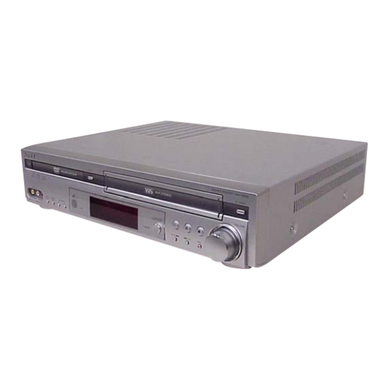
SERVICE MANUAL
Ver 1.0 2004.06
AVD-K150B/K150E/K150G/K150N/K150R is the
Amplifier, DVD/VIDEO player and tuner section
in DAV-D150B/D150E/D150G/D150N/D150R.
• Manufactured under license from Dolby Laboratories. "Dolby", "Pro
Logic", and the double-D symbol are trademarks of Dolby Laboratories.
Confidential unpublished works. Copyright 1992 -1997 Dolby
Laboratories. All rights reserved.
• DTS and DTS Digital Surround are registered trademarks of Digital
Theater Systems, Inc.
General
Power requirements
AC 230 V , 50/60 Hz
Power consumption
74W
Dimensions (approx.)
430 x 98 x 386 mm
x 15
Mass (approx.)
6.5 kg (14 lb 6 oz)
5 ° C to 35 ° C (41 ° F to 95 ° F)
Operating temperature
Operating humidity
5 % to 90 %
DVD Section
Laser
Semiconductor laser (Wavelength
DVD: 650nm, CD: 780nm)
Signal system
PAL
Frequency response
DVD (PCM 48 kHz): 10 Hz to 22 kHz
CD: 10 Hz to 20 kHz
Signal-to-noise ratio
More than 80 dB (ANALOG OUT
connectors only)
Harmonic distortion
Less than 0.05%
VIDEO Section
Head system
4 heads helical scan azimuth system
Television system
PAL B/G colour system (150E)
PAL B/G, SECAM L colour system (150B)
PAL I colour system (150G)
PAL B/G, SECAM D/K colour system (150N)
PAL (B/G, I/I), SECAM D/K colour system (150R)
Recording format
PAL
Tape speed
PAL/MESECAM; 23.39 mm/s (SP),
16.69 mm/s (LP)
Sony Corporation
9-877-959-01
Home Audio Company
2004F1678-1
Published by Sony Engineering Corporation
© 2004.06
AVD-K150B/K150E/K150G/
SPECIFICATIONS
(17 x 3
7
/
8
1
/
inches) (W x H x D)
4
K150N/K150R
Model Name Using Similar Mechanism NEW
DVD
Mechanism Type
Optical Pick-up Name
VCR
Mechanism Type
Maximum recording time
SP: 4 hour (E-240 tape), LP: 8 hour
(E-240 tape)
Rewind time
About 180 seconds (E-180 tape)
Input level
VIDEO: 1.0 V(p-p), 75 ohms, unbalanced
AUDIO: -6.0 dBm, more than 10 kohms (SCART)
DIGITAL AUDIO IN: Optical connector x 1
Output level
VIDEO: 1.0 V(p-p), 75 ohms, unbalanced
FM Tuner
Tuning Range
65 - 74 MHz (150R)
87.5 - 108.0 MHz (ALL MODEL)
Intermediate Frequency
10.7 MHz
AM Tuner
Tuning Range
522 - 1,611 kHz
Intermediate Frequency
450 kHz
Amplifier Section
70W + 70W (6 Ω at 1 kHz, THD 10 %)
Stereo mode
Front: 70W/ch (6 Ω at 1 kHz, THD 10 %)
Surround mode
Center*: 70W (6 Ω at 1 kHz, THD 10 %)
Surround*: 70W/ch (6 Ω at 1 kHz, THD 10 %)
Subwoofer*: 100W (4 Ω at 30 Hz, THD 10 %)
* Depending on the sound mode settings and the source,
there may be no sound output.
Inputs
AV 2, AV 3, OPTICAL IN (AV3 OPT)
• Design and specifications are subject to change without notice.
AEP Model
AVD-K150B/K150E/K150N/K150R
UK Model
AVD-K150G
DP-7C
PVR-502W
D35 (N)
-6.0 dBm, more than 47 kohms (RCA)
DVD/VCR RECEIVER
Advertisement
Table of Contents
Troubleshooting

Related Manuals for Sony AVD-K150E


Summarization of Contents
General Information
Rear Panel Overview
Overview of rear panel connectors and ports for external connections.
Connecting the System
TV and Decoder Connections
Guide for connecting TV and set-top boxes to the receiver.
Radio Aerial Connections
Instructions for connecting FM and AM antennas.
Digital Device Connections
Steps for connecting digital audio sources via optical input.
Speaker System Connections
How to connect speakers for optimal surround sound setup.
Disassembly Procedures
Cover and Front Panel Assembly
Procedure to remove the front panel and cover assembly.
Display and Key Board Removal
Steps to remove the display and key board.
Video Mechanism Deck Removal
Procedure to remove the video mechanism deck.
DVD Mechanism Deck Removal
Steps for removing the DVD mechanism deck.
SMPS Board Removal
Guide for removing the SMPS (Switch Mode Power Supply) board.
VCR Board Removal
Instructions for disassembling the VCR board.
DVD & AMP Board Removal
Procedure to remove the DVD and Amplifier board.
Electrical Adjustments and Troubleshooting
VCR Section Electrical Adjustment
Details on VCR servo and PG adjustment procedures.
Electrical Troubleshooting Guide
Troubleshooting flowchart for power (SMPS) and system/key circuits.
DVD & AMP Section Electrical Troubleshooting
Troubleshooting steps for DVD/AMP system operation and debugging.
Mechanical Adjustments
Tools and Fixtures for Service
Lists necessary tools and fixtures for mechanical adjustments.
Alignment Tapes for Adjustment
Specifies alignment tapes required for various VCR adjustments.
Preliminary Adjustment
Initial adjustment of tape guide line height on the lower drum.
Precise Adjustment
Detailed steps for precise guide roller height adjustment using an oscilloscope.
Audio/Control Head Adjustment
Procedures for adjusting A/C head height and tilt for accurate tape path.
Precise Adjustment (Azimuth)
Steps for precise azimuth adjustment of the A/C head for optimal signal.
X-Value Adjustment
How to adjust X-Value for compatibility with other VCR models.
Drum Assembly Replacement Adjustments
Procedures for adjusting roller guide and X value post-drum replacement.
Tape Travel Check After Reassembly
Verifying tape travel and audio/RF locking time after reassembly.
Diagrams and Schematics
DVD Overall Block Diagram
Overall block diagram of the DVD section.
VCR/Panel Block Diagram
Block diagram illustrating the VCR and panel sections.
DVD & AMP PWB (Component Side)
Component layout of the DVD & AMP board.
DVD & AMP Schematic - MPEG Section
Schematic for MPEG section of DVD & AMP board.
VCR Section Printed Wiring Board
Component layout of the VCR board.
VCR Schematic - System Section
Schematic for VCR system section of VCR board.
VCR Schematic - Hi-Fi/Switch Section
Schematic for Hi-Fi/Switch section of VCR board.
VCR Schematic - Power Section
Schematic for VCR power section of VCR board.
Display/Key Section PWB
Component layout of the Display/Key board.
SMPS Section Printed Wiring Board
Component layout of the SMPS board.
SMPS Section Schematic Diagram
Schematic diagram of the SMPS section.
Exploded Views
Front Panel Section Exploded View
Exploded view of the front panel assembly.
Overall Section Exploded View
Exploded view of the complete unit assembly.
DVD Mechanism Deck Exploded View
Exploded view of the DVD mechanism deck components.
Video Mechanism Deck -1 Exploded View
Exploded view of video mechanism deck parts.
Video Mechanism Deck -2 Exploded View
Exploded view of video mechanism deck parts.
Video Mechanism Deck -3 Exploded View
Exploded view of video mechanism deck parts.
Need help?
Do you have a question about the AVD-K150E and is the answer not in the manual?
Questions and answers