Table of Contents
Advertisement
CCD-TRV49/TRV49E/TRV58/TRV58E/TRV59E/TRV68/
SERVICE MANUAL
Ver 1.4 2002. 05
B MECHANISM
NTSC model : CCD- TR618/TR818/TRV49/TRV58/
TRV68/TRV78/TRV88/TRV98
PAL model
: CCD- TR618E/TR718E/TR728E/TRV49E/
TRV58E/TRV59E/TRV78E/TRV98E
CCD-TR618/TR618E/TR718E/TR728E/TR818
TRV78/TRV78E/TRV88/TRV98/TRV98E
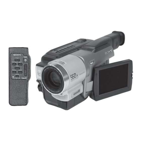
Photo : CCD-TRV98E
SPECIFICATIONS
CCD-TR818/TRV58/TRV68/TRV88/TRV98
CCD-TR818/TRV58/TRV68/TRV98
CCD-TR718E/TR728E/TRV58E/
CCD-TR618/TR618E/TR818/TRV49/
TRV49E/TRV58/TRV68/TRV78/
TRV78E/TRV88/TRV98/TRV98E
CCD-TR618E/TRV49E/TRV78E/TRV98E
CCD-TR618E/TRV49/TRV49E/TRV78/
CCD-TRV49/TRV49E/TRV78/
CCD-TR618E/TRV49E/TRV98E
For MECHANISM ADJUSTMENT, refer to
the "8mm Video MECHANICAL
ADJUSTMENT MANUAL
— Continued on next page —
VIDEO CAMERA RECORDER
RMT-708
US Model
Canadian Model
AEP Model
UK Model
TRV59E/TRV78E/TRV98E
E Model
Australian Model
Hong Kong Model
TRV78E/TRV98/TRV98E
Tourist Model
TRV78E/TRV98/TRV98E
Chinese Model
Brazilian Model
CCD-TR818/TRV58/TRV98
Argentina Model
CCD-TR818/TRV58
Korea Model
CCD-TRV49/TRV78/TRV98
" (9-973-801-11).
Advertisement
Chapters
Table of Contents

Related Manuals for Sony Handycam Vision CCD-TRV49


Summarization of Contents
SERVICE MANUAL
General
General information about the camcorder and its use, including checking accessories and quick start.
Specifications
Detailed technical specifications of the camcorder, including video and audio systems.
SAFETY-RELATED COMPONENT WARNING!!
ATTENTION AU COMPOSANT AYANT RAPPORT À LA SÉCURITÉ!
Warning regarding components critical to safe operation and their replacement with Sony parts.
SERVICE NOTE
POWER SUPPLY DURING REPAIRS
Method to prevent power shut-off during repairs by using the DC IN terminal.
TO TAKE OUT A CASSETTE WHEN NOT EJECT (FORCE EJECT)
Procedure for force ejecting a cassette when the unit does not eject it normally.
SELF-DIAGNOSIS FUNCTION
Self-diagnosis Function
Explanation of the self-diagnosis function that displays troubleshooting guidance on the viewfinder or LCD.
Self-diagnosis Display
Description of the 4-digit display showing repair status, block, and detailed codes for problems.
Service Mode Display
Explanation of the service mode display showing past self-diagnosis codes and how to access it.
SECTION 1 GENERAL
Checking supplied accessories
Instructions on how to verify that all necessary accessories are included with the camcorder.
Quick Start Guide
A brief guide to get the camcorder operational quickly, covering basic setup and connection.
Step 1 Preparing the power supply
To remove the battery pack
Instructions for removing the battery pack from the camcorder.
Charging the battery pack
Procedure for charging the camcorder's battery pack.
Step 2 Setting the date and time
To check the present date and time
Guide on how to view and verify the current date and time settings on the camcorder.
Step 3 Inserting a cassette
To eject camera
Instructions for ejecting the cassette from the camcorder.
For inserting cassettes
Step-by-step guide on how to properly insert a cassette into the camcorder.
Recording a picture
To prevent accidental erasure
Advice on how to avoid accidentally erasing the red mark on the tape.
Recording a picture
Basic steps for recording a video image using the camcorder.
Recording a picture
Using the zoom feature
Instructions on how to use the zoom function for capturing images at different distances.
Adjusting the brightness of the LCD screen
How to adjust the brightness of the LCD screen for better visibility.
Recording a picture
Shooting backlit subjects – BACK LIGHT
Guidance on how to properly shoot subjects that are backlit, using the BACK LIGHT feature.
Shooting in the dark – NightShot
Instructions for recording images in low-light conditions using the NightShot function.
Recording a picture
Superimposing the date and time on pictures
How to add the date and time information directly onto the recorded video images.
Checking the recording – END SEARCH
Method to check the recorded contents using the END SEARCH function to locate the end of the recorded tape.
Playback – Basics
Playing back a tape
Basic steps for playing back recorded video tapes on the camcorder.
To view the picture at slow speed
How to watch recorded footage at a slower playback speed.
Advanced Recording Operation
Using the wide mode
How to activate and use the wide mode for recording a wider field of view.
Using the fader function
Instructions on how to use the fader function to create smooth transitions between scenes.
Recording a picture
Using special effects – Picture effect
How to apply various visual effects to the recorded pictures to enhance their appearance.
Using the PROGRAM AE function
How to utilize the Program AE function for automatic exposure settings in different shooting scenarios.
Focusing manually
Focusing manually
Step-by-step guide on how to manually adjust the focus for sharper images.
Superimposing a title
Superimposing a title
How to add text titles directly onto the recorded video images.
Making your own titles
Instructions for creating and storing custom text titles to be superimposed on videos.
Using the built-in light
Using the built-in light
How to operate and utilize the camcorder's built-in light for illumination.
Replacing the light
Procedure for replacing the built-in light unit if it fails.
Editing
Dubbing a tape
How to duplicate video tapes by connecting the camcorder to another VCR or TV.
Customizing Your Camcorder
Changing the menu settings
How to modify the camcorder's settings through the menu system for personalized operation.
Changing the menu settings
Changing the menu settings
Detailed steps on how to adjust various settings within the camcorder's menu system.
Troubleshooting
Types of trouble and their solutions
Common problems encountered with the camcorder and their corresponding solutions.
Warning indicators and messages
Warning indicators and messages
Explanation of various warning indicators and messages displayed by the camcorder.
Additional Information
Usable cassettes and playback modes
Information on compatible cassette types and available playback modes for the camcorder.
About “InfoLITHIUM” battery
Details about the InfoLITHIUM battery, its features, and usage.
Maintenance information and precautions
Cleaning the Video lens
Instructions for properly cleaning the camcorder's video lens to maintain image quality.
Removing dust from inside the camcorder
Steps for safely removing dust from the interior of the camcorder.
Maintenance information and precautions
Precautions
Important precautions to follow when handling and maintaining the camcorder to prevent damage.
Built-in light
Information regarding the operation and maintenance of the camcorder's built-in light.
Identifying the parts and controls
Camcorder
Identification of the various external parts and controls of the camcorder.
Operation Indicators
Explanation of the different indicators on the camcorder's LCD screen and viewfinder.
Identifying the parts and controls
Identifying the parts and controls
Identification of additional external parts and controls of the camcorder.
Identifying the parts and controls
Identifying the parts and controls
Identification of the remote commander's parts and controls.
Operation Indicators
Explanation of the different indicators on the camcorder's LCD screen and viewfinder.
SECTION 2 DISASSEMBLY
2-1. Video light (Video light model)
Procedure for disassembling the video light component of the camcorder.
2-2. LCD section (PD-131 board) (TRV model)
Steps for disassembling the LCD section, specifically the PD-131 board in TRV models.
2-7. VF-129 BOARD (B/W EVF MODEL)
PRECAUTION DURING INSTALLATION
Precautions to take during the installation of the VF-129 board.
[SERVICE POSITION TO CHECK THE VTR SECTION]
Setting the “Forced VTR Power ON” mode
Steps to set the camcorder into a forced VTR power ON mode for service checks.
Exiting the “Forced VTR Power ON” mode
Procedure to exit the forced VTR power ON mode after service is completed.
[SERVICE POSITION TO CHECK THE CAMERA SECTION]
Setting the “Forced Camera Power ON” mode
Steps to set the camcorder into a forced camera power ON mode for service checks.
Exiting the “Forced Camera Power ON” mode
Procedure to exit the forced camera power ON mode after service is completed.
SECTION 3 BLOCK DIAGRAMS
3-1. OVERALL BLOCK DIAGRAM (1/2)
Overall block diagram illustrating the interconnections of major components, part 1.
3-2. OVERALL BLOCK DIAGRAM (2/2)
Overall block diagram illustrating the interconnections of major components, part 2.
SECTION 4 PRINTED WIRING BOARDS AND SCHEMATIC DIAGRAMS
4-1. FRAME SCHEMATIC DIAGRAM (1/2)
Schematic diagram of the camcorder's frame, part 1.
4-1. FRAME SCHEMATIC DIAGRAM (2/2)
Schematic diagram of the camcorder's frame, part 2.
4-2. PRINTED WIRING BOARDS AND SCHEMATIC DIAGRAMS
(For printed wiring boards)
Notes and conventions for interpreting the printed wiring boards.
(For schematic diagrams)
Notes and conventions for interpreting the schematic diagrams.
CD-281/286 (CCD IMAGER) PRINTED WIRING BOARD
Precautions Upon Replacing CCD imager
Important precautions to follow when replacing the CCD imager component.
MI-040/041 (STEADY SHOT, MIC AMP, IR DRIVE) PRINTED WIRING BOARD
For printed wiring board
Notes and conventions for interpreting the printed wiring board.
STEADY SHOT, MIC AMP
SIGNAL PATH
Diagram illustrating the signal paths for steady shot, microphone amplifier, and IR drive.
IR DRIVE
SIGNAL PATH
Diagram illustrating the signal paths related to the IR drive system.
PD-131 (RGB, TIMING GENERATOR, BACK LIGHT) PRINTED WIRING BOARD
For printed wiring board
Notes and conventions for interpreting the printed wiring board.
RGB, TIMING GENERATOR
SIGNAL PATH
Diagram illustrating the signal paths for RGB, timing generator, and back light.
BACK LIGHT
Note :
Important notes regarding components critical for safety and their replacement.
VF-129 (B/W EVF) PRINTED WIRING BOARD
For printed wiring board
Notes and conventions for interpreting the printed wiring board.
VF-141 (COLOR EVF) PRINTED WIRING BOARD
For printed wiring board
Notes and conventions for interpreting the printed wiring board.
EVF BACK LIGHT
Note :
Important notes regarding components critical for safety and their replacement.
SWITCH CF-077
For printed wiring board
Notes and conventions for interpreting the printed wiring board.
SWITCH CF-077
For Schematic Diagram
Schematic diagram for the CF-077 board.
VC-251 BOARD(SIDE A)
For printed wiring board
Notes and conventions for interpreting the printed wiring board.
CAMERA PROCESSOR AMP
SIGNAL PATH
Diagram illustrating the signal paths for the camera processor amplifier.
Y/C PROCESSOR
SIGNAL PATH
Diagram illustrating the signal paths for the Y/C processor.
REC/PB AMP
SIGNAL PATH
Diagram illustrating the signal paths for the REC/PB amplifier.
WAVEFORMS
CD-281/286, MI-040/041, PD-131, VF-129
Waveforms for various ICs on CD-281/286, MI-040/041, PD-131, and VF-129 boards.
WAVEFORMS
VF-141, LB-062, CF-077
Waveforms for various ICs on VF-141, LB-062, and CF-077 boards.
PARTS LOCATION
CD-281/286 BOARD (SIDE A)
Location of parts on the CD-281/286 board (Side A).
CD-281/286 BOARD (SIDE B)
Location of parts on the CD-281/286 board (Side B).
PARTS LOCATION
VF-129 BOARD (SIDE A)
Location of parts on the VF-129 board (Side A).
VF-129 BOARD (SIDE B)
Location of parts on the VF-129 board (Side B).
PARTS LOCATION
VC-251 BOARD (SIDE A)
Location of parts on the VC-251 board (Side A).
PARTS LOCATION
VC-251 (continued)
Location of parts on the VC-251 board (continued).
SECTION 5. ADJUSTMENTS
1-3. CAMERA SECTION ADJUSTMENT
Adjustments related to the camera section of the camcorder.
1. Before starting adjustment
1-1. Adjusting items when replacing main parts and boards
Table indicating adjustments needed when replacing specific main parts or boards.
1. Before starting adjustment
1-1. Adjusting items when replacing main parts and boards
Table indicating adjustments needed when replacing specific main parts or boards.
5-1. CAMERA SECTION ADJUSTMENT
1-1. PREPARATIONS BEFORE ADJUSTMENT (CAMERA SECTION)
Preparations required before performing camera section adjustments.
1-1-1. List of Service Tools
List of necessary service tools for camera section adjustments.
1-1-2. Preparations
Note1: For details of how remove the cabinet and boards
Reference to disassembly procedures for cabinets and boards.
Note4: As removing the cabinet (R) assembly (removing CN709 of the VC-251 board) means removing the lithium 3V power supply (CF-1000 block/CF-077 board BT101), data such as date, time, user-set menus will be lost. After completing adjustments, reset these data. If the cabinet (R) assembly has been removed, the self-diagnosis data, data on history of use (total drum rotation time etc.) will be lost. Before removing, note down the self-diagnosis data (data of page: 2, address: B0 to C6) and data on history use (data of page: 2, address: A2 to AA and E0 to E2). (Refer to “5-4. Service Mode” for the self-diagnosis data and data on the history use.)
Crucial note about data loss upon cabinet removal and the need to reset/record data.
TR model (CCD-TR618/TR618E/TR718E/TR728E/TR818)
Note: Use either a AC power adaptor or a Info-LITHIUM battery as the power supply of the CPC jig for BX/BK.
Note on power supply options for the CPC jig.
TRV model (CCD-TRV49/TRV49E/TRV58/TRV58E/TRV59E/TRV68/TRV78/TRV78E/TRV88/TRV98/TRV98E)
Note: Use either a AC power adaptor or a Info-LITHIUM battery as the power supply of the CPC jig for BX/BK.
Note on power supply options for the CPC jig.
1. Setting the Switch
Switch setting:
Specifies the switch positions required for adjustments.
1. Initializing the D, E, F, 7 Page Data
Note1: If “Initializing the D, E, F, 7 Page Data” is performed, all data of the D page, E page, F page and 7 page will be initialized. (It is impossible to initialize a single page.)
Warning about initializing entire pages and the impossibility of single-page initialization.
Note2: If the D, E, F, 7 page data has been initialized, “Modification of D, E, F, 7 Page Data” and all adjustments need to be performed again.
Information that re-initialization requires subsequent modification and adjustment.
2. Modification of D, E, F, 7 Page Data
Modifying Method:
Steps for modifying data addresses after page initialization.
3. D Page Table
Address Initial value Remark
Table detailing initial values for D page addresses and their remarks.
4. F Page table
Address Initial value Remark
Table detailing initial values for F page addresses and their remarks.
5. E Page Table
Address Initial value Remark
Table detailing initial values for E page addresses and their remarks.
6. 7 Page Table
Address Initial value Remark
Table detailing initial values for 7 page addresses and their remarks.
1-3. CAMERA SYSTEM ADJUSTMENTS
Note: NTSC model: CCD-TR618/TR818/TRV49/TRV58/TRV68/ TRV78/TRV88/TRV98
Notes on NTSC model specifications for camera system adjustments.
PAL model: CCD-TR618E/TR718E/TR728E/TRV49E/TRV58E/ TRV59E/TRV78E/TRV98E
Notes on PAL model specifications for camera system adjustments.
3. Flange Back Adjustment
Preparations:
Preparations required for the flange back adjustment procedure.
Specified voltage:
Information on the specified voltage required for the minipattern box.
4. Flange Back Adjustment
4-1. Flange Back Adjustment (1)
Procedure for the first part of the flange back adjustment.
4-2. Flange Back Adjustment (2)
Procedure for the second part of the flange back adjustment.
5. Flange Back Check
Checking method:
Method to check if the flange back adjustment was successful.
Processing after Completing Adjustments:
Steps to take after completing the flange back adjustment.
6. Picture Frame Setting
Switch setting:
Specifies the switch settings required for picture frame adjustment.
Setting method:
Method for adjusting the picture frame and position.
7. Color Reproduction Adjustment
Note: NTSC model: CCD-TR618/TR818/TRV49/TRV58/TRV68/ TRV78/TRV88/TRV98
Note on NTSC model specifications for color reproduction adjustment.
PAL model: CCD-TR618E/TR718E/TR728E/TRV49E/TRV58E/ TRV59E/TRV78E/TRV98E
Note on PAL model specifications for color reproduction adjustment.
8. Auto White Balance & LV Standard Data Input
Note1: This adjustment should be carried out upon completion of “Color reproduction adjustments”.
Note that this adjustment requires prior completion of color reproduction adjustments.
Note2: After the power is turned on, this adjustment can be done only once.
Warning that the auto white balance adjustment can only be performed once.
9. Auto White Balance Adjustment
Note1: 1/6 CCD NTSC model: CCD-TR618/TRV49/TRV58
Specifies 1/6 CCD NTSC models for auto white balance adjustment.
Note2: After the power is turned on, this adjustment can be done only once.
Warning that the auto white balance adjustment can only be performed once.
10. White Balance Check
Indoor white balance check
Procedure for checking white balance under indoor lighting conditions.
Outdoor white balance check
Procedure for checking white balance under outdoor lighting conditions.
11. Angular Velocity Sensor Sensitivity Adjustment
Precautions on the Parts Replacement
Precautions to take when replacing angular velocity sensors.
Precautions on Angular Velocity Sensor
Handling precautions for the angular velocity sensor due to its precision oscillator.
1-4. COLOR ELECTRONIC VIEWFINDER SYSTEM ADJUSTMENT
Note1: The back light (fluorescent tube) is driven by a high voltage AC power supply. Therefore, do not touch the back light holder to avoid electrical shock.
Safety warning regarding the high voltage AC power supply for the backlight.
Note2: When replacing the LCD unit, be careful to prevent damages caused by static electricity.
Precautionary note about preventing static electricity damage when replacing the LCD unit.
1. RGB AMP Adjustment (VF-141 board)
Set the D range of the RGB driver used to drive the LCD to the specified value. If deviated, the LCD screen will become blackish or saturated (whitish).
Procedure to set the RGB driver D range for the LCD.
2. Contrast Adjustment (VF-141 board)
Set the level of the VIDEO signal for driving the LCD to the specified value. If deviated, the screen image will be blackish or saturated (whitish).
Procedure to set the VIDEO signal level for the LCD.
3. Backlight Consumption Current Adjustment (LB-062 board)
Note1: Perform the adjustment in the following order.
Note specifying the order for performing backlight consumption current adjustment.
4. White Balance Adjustment (VF-141 board)
Note1: Check the white balance only when replacing the following parts. If necessary, adjust them.
Note on when to check and adjust white balance, especially after part replacement.
1-5-4. Aberration Adjustment
Adjusting method:
Method for adjusting the aberration of the viewfinder.
1-5-5. Horizontal Amplitude Adjustment (VF-129 board)
Adjusting method:
Method for adjusting the horizontal amplitude of the VF-129 board.
1-5-6. Vertical Amplitude Adjustment (VF-129 board)
Adjusting method:
Method for adjusting the vertical amplitude of the VF-129 board.
1-5-7. Brightness Adjustment (VF-129 board)
Adjusting method:
Method for adjusting the brightness of the VF-129 board.
1-6. LCD SYSTEM ADJUSTMENT
Note 1: The back light (fluorescent tube) is driven by a high voltage AC power supply. Therefore, do not touch the back light holder to avoid electrical shock.
Safety warning regarding the high voltage AC power supply for the backlight.
Note 2: When replacing the LCD unit, be careful to prevent damages caused by static electricity.
Precautionary note about preventing static electricity damage when replacing the LCD unit.
1. LCD Type Check
By measuring the resistor value between Pin 6 of CN5502 and GND, the type of LCD can be discriminated.
Method to discriminate LCD type by measuring resistor value.
2. VCO Adjustment (PD-131 board)
Set the VCO free-run frequency. If deviated, the LCD screen will be blurred.
Procedure to set the VCO free-run frequency for the LCD.
3. RGB AMP Adjustment (PD-131 board)
Set the D range of the RGB decoder used to drive the LCD to the specified value. If deviated, the LCD screen will become blackish or saturated (whitish).
Procedure to set the RGB decoder D range for the LCD.
4. Contrast Adjustment (PD-131 board)
Set the level of the VIDEO signal for driving the LCD to the specified value. If deviated, the screen image will be blackish or saturated (whitish).
Procedure to set the VIDEO signal level for the LCD.
5. COM AMP Adjustment (PD-131 board)
Set the common electrode drive signal level of LCD to the specified value.
Procedure to set the common electrode drive signal level for the LCD.
6. V-COM Adjustment (PD-131 board)
Set the DC bias of the common electrode drive signal of LCD to the specified value. If deviated, the LCD display will move, producing flicker and conspicuous vertical lines.
Procedure to set the DC bias of the LCD common electrode drive signal.
7. White Balance Adjustment (PD-131 board)
Correct the white balance. If deviated, the reproduction of the LCD screen may degenerate.
Procedure to correct the white balance of the LCD screen.
5-2. MECHANISM SECTION ADJUSTMENT
2-1. ADJUSTMENT REMOTE COMMANDER
Connecting and using the adjustment remote commander for mechanism adjustments.
2-2. OPERATING WITHOUT CASSETTE
Procedure for operating the unit without a cassette loaded.
2-3. TAPE PATH ADJUSTMENT
1. Preparations for Adjustment
Preparations required before performing tape path adjustments.
3-1. PREPARATIONS BEFORE ADJUSTMENTS
3-1-1. Equipment to Required
List of necessary measuring instruments for video section adjustments.
3-1-2. Precautions on Adjusting
Note1: TRV model: CCD-TRV49/TRV49E/TRV58/TRV58E/TRV59E/TRV68/ TRV78/TRV78E/TRV88/TRV98/TRV98E
Notes on TRV model specifications for adjustments.
Note4: Setting the “Forced Camera Power ON” mode (Camera mode)
Steps to set the camcorder into a forced camera power ON mode for service checks.
3-1-3. Adjusting Connectors
The following table shows the Pin No. and signal name of CN713 or CPC connector.
Pin assignment and signal names for CN713 or CPC connector.
The following table shows the arrangement of the test points of CPC jig for BX/BK. (Pin No. are those of CN713 or CPC connector.)
Arrangement of test points on the CPC jig for BX/BK.
3-1-5. Alignment Tape
Alignment tape
Table listing available alignment tapes and their usage.
3-1-6. Output Level and Impedance
Video output
Specifications for the camcorder's video output level and impedance.
Audio output
Specifications for the camcorder's audio output level and impedance.
3-2. SYSTEM CONTROL SYSTEM ADJUSTMENT
1. Initialization of D, E, F, 7 Page Data
Procedure for initializing the D, E, F, and 7 page data.
3-3. SERVO SYSTEM ADJUSTMENT
1. CAP FG Offset Adjustment (VC-251 board)
Adjustment for CAP FG offset to ensure proper capstan servo operation.
1. 28 MHz Origin Oscillation Adjustment (VC-251 board)
Set the frequency of the clock for synchronization. If deviated, the synchronization will be disrupted and the color will become inconsistent.
Procedure to set the clock frequency for synchronization.
2. AFC fo Adjustment (VC-251 board)
Adjust the pull-in range of the A/D converted clock generator during playback.
Procedure to adjust the pull-in range of the A/D converted clock generator.
3. Filter fo Adjustment (VC-251 board)
Adjust the fo frequency of the IC151 built-in filter.
Procedure to adjust the fo frequency of the IC151 built-in filter.
4. Y OUT Level Adjustment (VC-251 board)
Set the Y signal output level. (Adjust the D/A converter out put level of IC151.)
Procedure to set the Y signal output level.
5. C OUT Level Adjustment (VC-251 board)
Set the chroma signal output level. (Adjust the D/A converter out put level of IC151.)
Procedure to set the chroma signal output level.
6. REC Y Current Adjustment (VC-251 board)
Adjust the Y FM signal recording current.
Procedure to adjust the Y FM signal recording current.
Note1: Don’t disconnect the DC power supply of the camcorder during the following adjustments.
Important note about not disconnecting the DC power supply during adjustments.
7. REC C/AFM Current Adjustment (VC-251 board)
Note: Use the REC buttons of the adjustment remote commander (with the HOLD switch set in the OFF position).
Note on using the REC buttons of the remote commander.
7-2. REC C Current Check (VC-251 board)
Procedure to check REC Chroma signal current and its implications.
7-3. REC AFM Current Adjustment (VC-251 board)
Set the recording levels of the REC AFM signal. If the level is too low, the audio S/N will be deteriorated. If too high, color beets will be produced on the self-recording / playback image.
Procedure to set REC AFM signal levels for optimal audio S/N and color.
3-5. IR TRANSMITTER ADJUSTMENTS
Note: If the distance between the IR receiver jig and the camcorder is below 1m, cover the LASER LINK emitter with a ND filter. (For example, when the distance is 30cm to 50cm, cover the LASER LINK emitter with a ND filter 1.0.)
Note about using an ND filter when the IR receiver jig is close to the camcorder.
Switch setting:
Specifies the switch setting for IR transmitter adjustments.
2. IR Video Deviation Adjustment (MI-041 board)
Mode VTR stop
Mode setting for IR video deviation adjustment.
Connection of Equipment:
Instructions for connecting equipment for IR video deviation adjustment.
3. IR Audio Deviation Adjustment (MI-041 board)
Note: This adjustment should be carried out upon completion of the audio system adjustments.
Note that this adjustment should be done after audio system adjustments are complete.
3-6. AUDIO SYSTEM ADJUSTMENTS
[Connecting the measuring instruments for the audio]
Instructions for connecting audio measuring instruments.
2. BPF fo Adjustment (VC-251 board)
Sets the BPF passing frequency of IC760 so that the AFM signal can separate from the playback RF signal properly. If deviated. the mono/stereo mode will be differentiated incorrectly, and noises and distortions will increase during high volume playback.
Procedure to set BPF frequency for AFM signal separation.
5-4. SERVICE MODE
1. Using the Adjustment Remote Commander
Guide on how to use the adjustment remote commander for service mode operations.
2. Precautions Upon Using the Adjustment Remote Commander
Precautions to take when using the adjustment remote commander to prevent data loss.
4-2. DATA PROCESS
Hexadecimal-decimal Conversion Table
Table for converting hexadecimal notation to decimal notation and vice versa.
4-3. SERVICE MODE
1. Test Mode Setting
Instructions for setting and releasing various test modes.
Note: For page D and F, the data set will be recorded in the nonvolatile memory by pressing the PAUSE button on the adjustment remote commander. Take note that, in this case, the test mode will not be released even if the main power has been turned off.
Important note about data saving and test mode behavior.
2. Emergency Memory Address
Note 1: Be sure to rewrite the data of addresses 10 to 1B to 00 after repairs/ adjustments.
Instruction to reset emergency memory addresses to 00 after repairs or adjustments.
Note 2: When rewriting the data, be sure to press the PAUSE button of the remote commander after setting the data.
Instruction to press PAUSE button after rewriting data for remote commander.
2-2. MSW codes
Contents
Table defining MSW codes for mechanism positions and their contents.
3. Bit Value Discrimination
(Example) If the remote commander display is “8E”, bit value from bit 7 to bit 4 can be discriminated from the column A, and those from bit 3 to bit 0 from column B.
Example illustrating how to discriminate bit values from the remote commander display.
Using method:
Method for discriminating switch states based on display data.
4. Switch check (1)
Using method:
Method for discriminating switch states based on display data.
5. Switch check (2)
Using method:
Method for discriminating switch states based on display data.
6. Switch check (3)
Using method:
Method for discriminating switch states based on display data.
8. Record of Use check
Note: When replacing the drum assembly, initialize the data of address: A2 to A4. When replacing the video light, initialize the data of address: E0 to E2.
Note on initializing data for drum assembly and video light replacement.
9. Record of Self-diagnosis check
Using method:
Method for viewing past self-diagnosis codes on page 2, addresses BC to C6.
SECTION 6. REPAIR PARTS LIST
6-1. EXPLODED VIEWS
Visual exploded views of the camcorder's components for repair identification.
6-1-5. CABINET (R) SECTION
Exploded view of the Type S and Type M cabinet (R) sections.
6-1-7. LENS SECTION
Be sure to read “Precautions upon replacing CCD imager” on page 4-8 when changing the CCD imager.
Note regarding precautions for CCD imager replacement.
6-2. ELECTRICAL PARTS LIST
NOTE:
General notes regarding parts list conventions and standardization.
VC-251 BOARD, COMPLETE
< CAPACITOR >
List of capacitors used on the VC-251 board.
MI-040 MI-041
< RESISTOR >
List of resistors used on the MI-040/MI-041 boards.
VC-251
< CAPACITOR >
List of capacitors used on the VC-251 board.
VC-251
< RESISTOR >
List of resistors used on the VC-251 board.
VC-251
< CAPACITOR >
List of capacitors used on the VC-251 board.
Type M
< CAPACITOR >
List of capacitors used on Type M models.
Type M
< RESISTOR >
List of resistors used on Type M models.
Type M
< RESISTOR >
List of resistors used on Type M models.
Type M
< RESISTOR >
List of resistors used on Type M models.
Type M
< RESISTOR >
List of resistors used on Type M models.
Type M
< RESISTOR >
List of resistors used on Type M models.
Type M
< RESISTOR >
List of resistors used on Type M models.
Type M
< VARIABLE RESISTOR >
List of variable resistors used.
VF-129 VF-141
< CAPACITOR >
List of capacitors used on VF-129 and VF-141 boards.
VC-251
< CONNECTOR >
List of connectors used on the VC-251 board.
< DIODE >
List of diodes used on the VC-251 board.
VC-251
< RESISTOR >
List of resistors used on the VC-251 board.
Type M
< RESISTOR >
List of resistors used on Type M models.
Type M
< RESISTOR >
List of resistors used on Type M models.
Type M
< RESISTOR >
List of resistors used on Type M models.
Type M
< RESISTOR >
List of resistors used on Type M models.
Type M
< RESISTOR >
List of resistors used on Type M models.
Type M
< RESISTOR >
List of resistors used on Type M models.
Type M
< RESISTOR >
List of resistors used on Type M models.
Type M
< RESISTOR >
List of resistors used on Type M models.
Type M
< RESISTOR >
List of resistors used on Type M models.
Type M
< RESISTOR >
List of resistors used on Type M models.
Type M
< RESISTOR >
List of resistors used on Type M models.
Type M
< RESISTOR >
List of resistors used on Type M models.
〈FOR CAMERA COLOR REPRODUCTION ADJUSTMENT〉
For NTSC model TYPE M
Color reproduction adjustment chart for NTSC models with Type M CCD.
For NTSC model TYPE S
Color reproduction adjustment chart for NTSC models with Type S CCD.
〈FOR CAMERA COLOR REPRODUCTION ADJUSTMENT〉
For PAL model
Color reproduction adjustment chart for PAL models.
SERVICE MANUAL SUPPLEMENT-2
Subject
Description of the supplement regarding CCD imager changes.
Note1: See Section “5. Adjustment, 1-6. LCD System Adjustment, 1. LCD Type Check”.
Reference to LCD Type Check section for identifying LCD types.
1-6. LCD SYSTEM ADJUSTMENT
1. LCD Type Check
Method to discriminate LCD type by measuring resistor value.
4. Contrast Adjustment (PD-131 board)
Adjustment Address ED
Adjustment address for contrast adjustment on PD-131 board.
5. COM AMP Adjustment (PD-131 board)
Adjustment Address ED
Adjustment address for COM AMP adjustment on PD-131 board.
Need help?
Do you have a question about the Handycam Vision CCD-TRV49 and is the answer not in the manual?
Questions and answers