Table of Contents
Advertisement
HCD-GX25/RG220
SERVICE MANUAL
Ver 1.0 2003. 08
• HCD-GX25/RG220 is the
tuner, deck, CD and amplifier
section in MHC-GX25/RG220.
AUDIO POWER SPECIFICATIONS
(HCD-GX25 USA model only)
POWER OUTPUT AND TOTAL HARMONIC
DISTORTION:
With 6 ohm loads, both channels driven, from
120 – 10,000 Hz; rated 120 watts per channel
minimum RMS power, with no more than 10 %
total harmonic distortion from 250 milliwatts to
rated output.
Amplifier section
North American models:
HCD-GX25:
Continuous RMS power output (reference):
120 + 120 watts (6 ohms at
1 kHz, 10% THD)
Total harmonic distortion less than 0.07% (6 ohms at
1 kHz, 60 W)
European and Russian models:
HCD-RG220:
DIN power output (rated): 50 + 50 watts
(6 ohms at 1 kHz, DIN)
Continuous RMS power output (reference):
60 + 60 watts (6 ohms at
1 kHz, 10% THD)
Music power output (reference):
120 + 120 watts (6 ohms at
1 kHz, 10% THD)
Sony Corporation
9-961-149-01
2003H04-1
Home Audio Company
© 2003. 08
Published by Sony Engineering Corporation
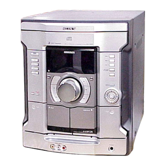
(Photo: HCD-GX25)
Model Name Using Similar Mechanism
CD Mechanism Type
CD
Section
Base Unit Name
Optical Pick-up Block
Tape Deck Model Name Using Similar Machanism
Section
Tape Transport Mechanism Type
SPECIFICATIONS
Other models:
HCD-RG220:
The following measured at AC 120, 127, 220, 240 V,
50/60 Hz
DIN power output (rated): 80 + 80 watts
Continuous RMS power output (reference):
Inputs
GAME INPUT AUDIO L/R (phono jacks):
GAME INPUT VIDEO (phono jack):
Outputs
PHONES (stereo mini jack):
VIDEO OUT (phono jack): max. output level
SPEAKER:
COMPACT DISC DECK RECEIVER
US Model
Canadian Model
AEP Model
UK Model
E Model
Australian Model
HCD-RG220
HCD-GX45/RG440
CDM74F-K6BD71A
CDM74F-K6BD72
BU-K6BD71A
BU-K6BD72
KSM-213DCP
HCD-GX45/RG440
CWM43FF-13
(6 ohms at 1 kHz, DIN)
100 + 100 watts (6 ohms at
1 kHz, 10% THD)
voltage 250 mV,
impedance 47 kilohms
1 Vp-p, 75 ohms
accepts headphones of
8 ohms or more
1 Vp-p, unbalanced, Sync
negative, load impedance
75 ohms
accepts impedance of 6 to
16 ohms
– Continued on next page –
HCD-GX25
1
Advertisement
Table of Contents

Summarization of Contents
SERVICE MANUAL
AUDIO POWER SPECIFICATIONS
Power output and total harmonic distortion for amplifier.
Amplifier section details
Amplifier output specs for North American, European, and Russian models.
Technical Specifications
Key specs for CD, Tape, Tuner, Amplifier including power, inputs, outputs.
SAFETY CHECK-OUT Procedures
AC LEAKAGE TEST METHODS
Procedures for measuring AC leakage current from exposed parts.
SECTION 1 GENERAL
Button Location Guide
Instructions for finding button locations and reference pages.
Main Unit Button Descriptions
Detailed descriptions of main unit buttons with illustration numbers.
SECTION 2 DISASSEMBLY Flowchart
2-1. CASE (TOP) Removal
Step-by-step guide for removing the top case.
2-2. CD DOOR Removal
Procedure to remove the CD door.
2-3. CD MECHANISM BLOCK Removal
Instructions for removing the CD mechanism block.
SECTION 3 TEST MODES
COLD RESET Procedure
Resets system data and clears RAM to initial conditions.
TUNER STEP CHANGE-OVER
Adjusts AM channel tuning step between 9 kHz and 10 kHz.
CD SHIP MODE Procedure
Secures optical pick-up for safe transport after repair.
CD TRAY LOCK MODE
Locks CD tray to prevent unauthorized disc removal.
AMP TEST MODE Procedure
Checks amplifier IC, tone quality, and VACS levels.
AGING MODE Operation
Aging Mode Display States
How the aging mode shows CD and tape deck operational status.
CD Section Aging Sequence
Steps performed by the CD section during aging mode.
Tape Deck Aging Sequence
Steps performed by the tape deck section during aging mode.
SECTION 4 ELECTRICAL ADJUSTMENTS
CD SECTION Adjustment Notes
Notes regarding adjustments for the CD block.
S-CURVE CHECK Procedure
Steps for checking the S-curve waveform for symmetry and peak level.
RF LEVEL CHECK Procedure
Steps for verifying RF signal clarity and level.
SECTION 5 DIAGRAMS
IC PIN DESCRIPTIONS (MAIN BOARD)
Pinout for IC309 BU2099FV (MULTI CONTROLLER) on the main board.
NOTES ON DIAGRAMS AND BOARDS
Printed Wiring Board Notes
Key to symbols used on printed wiring board diagrams.
Schematic Diagram Notes
Key to symbols and notations in schematic diagrams.
5-31. IC BLOCK DIAGRAMS
IC201 HA12237F Block Diagram
Detailed block diagram for IC201 HA12237F on the main board.
SECTION 6 EXPLODED VIEWS
6-1. MAIN SECTION Exploded View
Exploded view of the main unit assembly and parts.
SECTION 7 ELECTRICAL PARTS LIST
Electrical Parts List (ICs, Transistors, Resistors)
List of ICs, transistors, resistors, connectors, and ferrite beads for BD board.
Electrical Parts List (Resistors, Switches, Connectors, Diodes)
List of resistors, switches, connectors, and diodes for Game/HP Jack boards.
Electrical Parts List (Capacitors, Jacks, Switches)
List of capacitors, jacks, switches, and connectors for various boards.
Electrical Parts List (Capacitors, Connectors, Diodes)
List of capacitors, connectors, and diodes for the main board.
Electrical Parts List (Transistors, Resistors, ICs)
List of transistors, resistors, and ICs for the main board.
Electrical Parts List (Resistors, Transistors)
List of resistors and transistors for the power amp section.
Electrical Parts List (Transistors, Resistors, Coils, Diodes)
List of transistors, resistors, coils, and diodes for the power amp section.
Electrical Parts List (ICs, Transistors, Resistors)
List of ICs, transistors, and resistors for the panel section.
Electrical Parts List (Resistors)
List of resistors for the panel section.
Electrical Parts List (Switches, Vibrator, Connectors, Capacitors)
List of switches, vibrator, connectors, and capacitors for the panel section.
Electrical Parts List (Capacitors, Diodes, Transistors, Coils)
List of capacitors, diodes, transistors, and coils for the power amp section.
Electrical Parts List (Transistors, Resistors)
List of transistors and resistors for the power amp section.
Electrical Parts List (Resistors, Relays, Thermistors)
List of resistors, relays, and thermistors for the power amp section.
Electrical Parts List (Connectors, ICs, Switches, Transformers)
List of components for remote, sensor, transformer, and video sections.
MISCELLANEOUS PARTS LIST
List of miscellaneous parts including wires, cords, fuses, fans, and tuners.


Need help?
Do you have a question about the HCD-RG220 and is the answer not in the manual?
Questions and answers