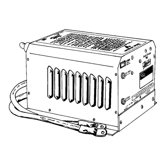
Summarization of Contents
INTRODUCTION
Product Functions
Outlines the three main functions: inverting, transfer switching, and battery charging.
THINGS YOU SHOULD KNOW
Circuit Breaker Protection
Details the circuit breakers protecting the unit from overloads and short circuits.
Low and High Battery Protection
Explains automatic shutdown based on battery voltage limits.
Power Sharing
Describes the feature that balances AC consumption between charger and loads.
OPERATION
Power Switch
Explains the function and use of the unit's power switch.
BATTERIES
Wet Cell Batteries
Details characteristics and requirements for wet cell deep-cycle batteries.
Common marine/RV deep-cycle batteries
Discusses the suitability and performance of marine/RV deep-cycle batteries.
Gel Cell Batteries
Describes gel cell batteries, their features, and maintenance needs.
Advanced AGM Batteries
Explains Absorbed Glass Mat batteries, their properties and maintenance.
Battery Selection
Guides on choosing batteries based on deep cycle capability and Amp-hour rating.
Battery Interconnection
Explains series and parallel connection methods for battery banks.
Battery Bank Ratings and Sizing
Guides on selecting and sizing battery banks based on capacity and discharge.
Amp-Hour Consumption Formulas
Provides formulas to calculate DC amp-hour draw for system planning.
Typical Power Consumption
Lists typical power consumption for various AC appliances.
BATTERY CHARGING
Conventional Battery Chargers
Contrasts conventional chargers with the Freedom Charger's capabilities.
Freedom Battery Chargers
Highlights the 3-stage charging process of Freedom chargers.
Bulk Charge Stage
Explains the first stage of charging, delivering most of the charge current.
Acceptance Charge Stage
Details the second stage where voltage is constant and current reduces.
Float Charge Stage
Describes the final stage for long-term battery maintenance.
Equalizing Charge Stage
Explains the controlled overcharge to balance cells and remove sulfate.
Charging Over-Discharged Batteries
Provides guidance on safely charging deeply discharged batteries.
Battery Charging Warnings
Lists important warnings and precautions for battery charging procedures.
Battery Charger Voltage Settings
Lists specific voltage settings for different battery types and temperatures.
INSTALLATION
Key Installation Points
Covers essential considerations like polarity, back-feeding, and wiring.
Installation Guidelines
Provides instructions for mounting, cable management, and system integration.
Grounding
Explains the importance and procedure for connecting the unit to the AC ground system.
Neutral Bonding
Describes how the unit internally bonds neutral and ground for safety.
AC Wiring
Details the process for connecting AC input and output wires.
Ground Fault Circuit Interrupters
Recommends specific GFCI receptacles for safety compliance.
Remote Control Wiring
Guides on routing the remote control cable to avoid interference.
DC Wiring
Explains proper connection of DC battery cables and their sizing.
Battery Cable Fusing
Specifies the requirement and placement of fuses for battery cables.
Recommended Fuse
Identifies the specific fuse type and part numbers for the unit.
Start Up and Testing Procedures
Outlines steps to verify installation correctness, including inverter and transfer tests.
TROUBLESHOOTING
No Inverter Output
Lists checks for when the unit fails to produce AC power.
Little or No Output from Battery Charger
Provides troubleshooting steps for a non-functional battery charger.
Microwave Oven Cooking Slow
Explains why microwave cooking might be slow and how to improve it.
Troubleshooting Specific LEDs
Lists indications for specific LEDs (8, 7, 6, 5, 4, 2, 1) when an overload occurs.
REMOTE CONTROL PANEL
Remote Power Switch
Explains the function of the power switch on the remote control panel.
System Status LEDs
Describes the meaning of the 4 system status LEDs on the panel.
DC Volts Bargraph
Explains how the DC Volts bargraph indicates battery voltage and settings.
DC Amps Bargraph
Details the DC Amps bargraph for monitoring current in different modes.
Dip Switch Functionality
Explains the role of dip switches for configuration of charger and inverter settings.
Dip Switch Status
Explains how to view current dip switch settings via the display.
Remote Control Wiring
Guides on connecting the remote panel cable and routing it properly.
Dip Switch Programming Chart
Provides a detailed table for setting the 8 dip switches for various functions.
REMOTE CONTROL PANEL STATUS LEDs
INV/CHRG LED
Explains the INV/CHRG status LED indicating power and charger operation.
AC Input LED
Describes the AC Input LED indicating when AC power is applied.
Overload LEDs
Details the meaning of steady and blinking overload LEDs for shutdown conditions.
Battery Status LEDs
Explains the battery status LEDs for warning, shutdown, and equalizing conditions.
GLOSSARY
Glossary Terms
Defines technical terms used throughout the manual for better understanding.
WARRANTY
Warranty Service Information
Outlines the limited warranty period and procedures for obtaining service.


Need help?
Do you have a question about the 25 and is the answer not in the manual?
Questions and answers