Table of Contents
Advertisement
SERVICE MANUAL
1
2
3
4
5
6
7
8
9
0
Refer to the SERVICE MANUAL of VHS MECHANICAL
ADJUSTMENT
for MECHANICAL ADJUSTMENTS.
(9-921-748-11)
System
Format
VHS NTSC standard
Video recording system
Rotary head helical scanning FM system
Video heads
Double azimuth four heads
Video signal
NTSC color, EIA standards
Tape speed
SP: 33.35 mm/s
EP: 11.11 mm/s
LP: 16.67 mm/s,
playback only
Maximum recording/playback time
9 hrs. in EP mode (with T-180 tape)
Fast-forward and rewind time
Approx. 3 min. (with T-120 tape)
Tuner section
Channel coverage
VHF 2 to 13
UHF 14 to 69
CATV A-8 to A-1, A to W, W+1 to W+84
Antenna
75-ohm antenna terminal for VHF/UHF
Input and outputs
LINE-1 IN and -2 IN
VIDEO IN, phono jack (1 each)
Input signal: 1 Vp-p, 75 ohms, unbalanced, sync
negative
AUDIO IN, phono jacks (1 each) (SLV-LX50
and LX40), (2 each) (SLV-LX70S and LX60S)
Input level: 327 mVrms
Input impedance: more than 47 kilohms
LX40/LX50/LX60S/LX70S
SLV-LX70S
HiFi model : SLV-LX60S/LX70S
Mono model: SLV-LX40/LX50
SPECIFICATIONS
LINE OUT
VIDEO OUT, phono jack (1)
Output signal: 1 Vp-p, 75 ohms, unbalanced,
sync negative
AUDIO OUT, phono jacks (1 each) (SLV-LX50
and LX40), (2 each) (SLV-LX70S and LX60S)
Standard output: 327 mVrms
Load impedance: 47 kilohms
Output impedance: less than 10 kilohms
Timer section
Clock
Quartz locked
Timer indication
12-hour cycle
Timer setting
8 programs (max.)
Power back-up
Built-in self-charging capacitor
Back-up duration: up to 8 hours at a time
General
Power requirements
110 V AC to 240 V AC, 50/60 Hz
(SLV-LX70S (CL/CS) and LX50 (CL/CS))
120 V AC, 60 Hz
(SLV-LX70S (MX/PA/PC/VZ), LX60S (MX),
LX50 (MX/PA/PC/VZ), and LX40 (MX))
Power consumption
17 W
(SLV-LX70S (CL/CS/MX/PA/PC/VZ) and
SLV-LX60S (MX))
— 1 —
RMT-V293A/V294A
Chilean Model
SLV-LX50CL/LX50CS/LX70SCL/
Mexican Model
SLV-LX40MX/LX50MX/LX60SMX/
Panama Model
Venezuelan Model
SLV-LX50PA/LX50PC/LX50VZ/
LX70SPA/LX70SPC/LX70SVZ
16 W
(SLV-LX50 (CL/CS/MX/PA/PC/VZ) and
SLV-LX40 (MX))
Operating temperature
5°C to 40°C (41°F to 104°F)
Storage temperature
–20°C to 60°C (–4°F to 140°F)
Dimensions
Approx. 355 x 96 x 288.8 mm (w/h/d)
including projecting parts and controls
Mass
Approx. 3.6 kg
Supplied accessories
Remote commander (1)
Size AA (R6) batteries (2)
75-ohm coaxial cable with F-type connectors (1)
Audio/video cable (1) (3-phono to 3-phono)
(SLV-LX70S and LX60S only)
Plug adaptor (1)
(SLV-LX70S (CL/CS) and LX50 (CL/CS) only)
Design and specifications are subject to change
without notice
ENERGY STAR
As an ENERGY STAR
has determined that this product meets the
ENERGY STAR
VIDEO CASSETTE RECORDER
LX70SCS
LX70SMX
S MECHANISM
®
is a U.S. registered mark.
®
Partner, Sony Corporation
®
Advertisement
Table of Contents

Related Manuals for Sony LX70S


Summarization of Contents
SPECIFICATIONS
System
Detailed technical specifications of the VCR's internal systems.
Tuner section
Specifications related to the VCR's tuner and channel reception.
Input and outputs
Details of audio/video input and output jacks.
Timer section
Specifications for timer functions like clock and recording programs.
General
General VCR specifications including power, dimensions, and environment.
SAFETY CHECK-OUT
Safety Checks
Post-repair checks to ensure safe operation before releasing the unit.
ERROR CODE INDICATION
Error Codes
List and explanation of error codes displayed by the VCR.
Mode Codes
List and explanation of operational modes indicated by VCR codes.
SECTION 1 GENERAL
Setting up the remote commander
Instructions for remote battery installation and basic operation.
Hookups
Guidance on connecting the VCR to a TV and other devices.
Controlling other TVs with the remote commander
Using the remote to control non-Sony TVs.
Hookup 1
Antenna hookup
Steps for connecting the VCR using an antenna.
Hookup 1: VCR setup
Initial setup procedure for the antenna hookup.
Hookup 2
Hookup 2: VCR setup
Initial setup procedure for Hookup 2 connection.
Hookup 3
Hookup 3: VCR setup
Initial setup procedure for Hookup 3 connection.
Selecting a language
Setting the clock
Instructions for setting the VCR's internal clock.
Using Manual Clock Set
Manual Clock Setting Procedure
Step-by-step guide for manually setting the clock.
Presetting channels
Presetting all receivable channels automatically
Process for automatic channel tuning and storage.
Presetting/disabling channels manually
Manual control over channel selection and disabling.
Basic Operations
Playing a tape
Instructions for playing video tapes.
Turning on the VCR and TV, and starting playback automatically
Using Trinitron TV Synchro Play feature.
Recording TV programs
Recording TV programs using the Dial Timer
Setting up timed recordings with the Dial Timer.
Recording TV programs using the timer
Daily/weekly recording
Setting up recurring timer recordings.
Additional Operations
Playing/searching at various speeds
Navigating tape content at different playback speeds.
Locking the VCR (Child Lock)
Enabling child lock to prevent setting changes.
Setting the recording duration time
Checking/changing/canceling timer settings
Managing programmed timer recordings.
How sound is recorded on a video tape
Searching for the beginning of a timer recorded program
Locating the start of recorded segments.
Searching using the index function
Searching using the Time Search function
Finding specific points on tape via time codes.
Skip-searching automatically (Quick View)
Searching for a selected point on the tape
Using the tape indicator bar to find points.
Adjusting the picture
Adjusting the tracking
Manual adjustment for picture clarity.
About the Reality Regenerator function
Function to restore picture quality.
Changing menu options
About the Adaptive Picture Control (APC) function
VCR's automatic adjustment for tape and head conditions.
Editing with another VCR
How to connect to record on this VCR
Connecting for VCR-to-VCR recording.
Operation (when recording on this VCR)
Steps for editing with another VCR.
Additional Information
General setup information
VCR setup and RF unit settings.
Attaching the external antenna connector
Connecting antenna accessories.
Attaching a UHF/VHF band mixer
Using a band mixer for antenna signals.
Index to parts and controls
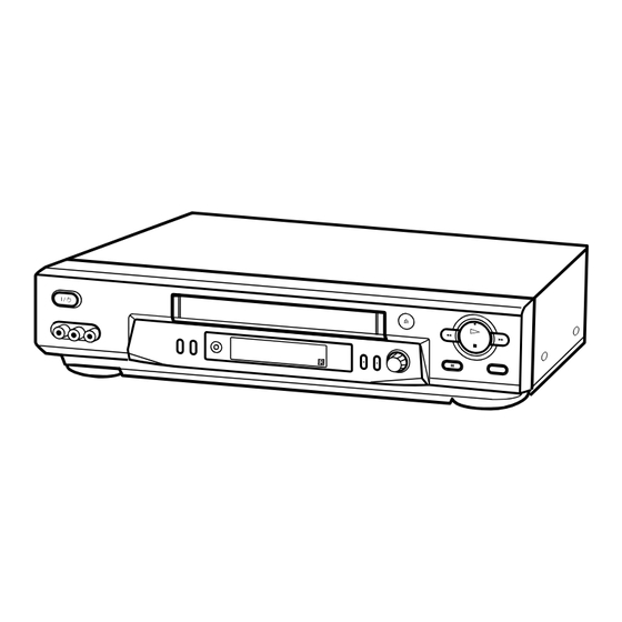
Front panel
Identification of front panel controls and indicators.
SECTION 2 DISASSEMBLY
2-1. CASE, FRONT PANEL BLOCK ASSEMBLY
Steps to disassemble the front panel and case.
2-2. DI-80 BOARD, FJ-32 BOARD
Disassembly of DI-80 and FJ-32 circuit boards.
2-6. INTERNAL VIEWS
Top View
Diagrams showing internal components from the top.
Bottom View
Diagrams showing internal components from the bottom.
SECTION 3 BLOCK DIAGRAMS
3-1. OVERALL BLOCK DIAGRAM
High-level system overview.
SECTION 4 PRINTED WIRING BOARDS AND SCHEMATIC DIAGRAMS
4-1. FRAME SCHEMATIC DIAGRAM
Overall schematic layout of major components.
4-2. PRINTED WIRING BOARDS AND SCHEMATIC DIAGRAMS
Reference to detailed board diagrams.
SECTION 5 INTERFACE, IC PIN FUNCTION DESCRIPTION
5-1. SYSTEM CONTROL - MECHANISM BLOCK INTERFACE (MA-405 BOARD IC160)
Pin functions for mechanism control.
5-2. SYSTEM CONTROL - SERVO PERIPHERAL CIRCUIT INTERFACE (MA-405 BOARD IC160)
Pin functions for servo circuits.
SECTION 6 ADJUSTMENTS
6-1 MECHANICAL ADJUSTMENTS
Adjustments related to the VCR's mechanical components.
6-2 ELECTRICAL ADJUSTMENTS
Adjustments related to the VCR's electrical circuits.
2-1. PREPARATION BEFORE ADJUSTMENT
2-1-1. Equipment Required
List of measuring instruments and tapes for alignment.
2-1-2. Equipment Connection
Diagram showing measurement instrument setup.
2-1-3. Set-up of Adjustment
Procedure for setting up the NTSC pattern generator.
2-1-4. Alignment Tape
Details of the KRV-51N2 alignment tape.
2-2. POWER SUPPLY CHECK
2-2-1. Output Voltage Check (MA-405 Board)
Checking specific output voltages on the MA-405 board.
2-3. SERVO SYSTEM CHECK
2-3-1. RF Switching Position Adjustment (MA-405 Board)
Adjusting tape playback output links for compatibility.
2-4. AUDIO SYSTEM ADJUSTMENT
2-4-1. Hi-Fi Audio System Adjustment (Hi-Fi model only)
Adjustment settings for Hi-Fi audio system.
2-4-2. HiFi Switching Position Adjustment (MA-405 Board)
Adjusting Hi-Fi playback output links.
2-4-3. Normal Audio System Adjustment
Adjusting normal audio system for SP mode.
2-4-4. Audio Level and Distortion Check
Verifying audio levels and distortion within specifications.
2-4-5. Audio Noise Check
Confirming audio noise levels meet specifications.
2-4-6. ACE Head Adjustment
Referencing manual for ACE head adjustment procedure.
2-4-7. E-E Output Level Check
Checking output level against reference input.
2-4-8. Frequency Response Check
Confirming frequency characteristics meet specifications.
SECTION 7 REPAIR PARTS LIST
7-1. EXPLODED VIEWS
Visual breakdown of VCR parts.
7-2. ELECTRICAL PARTS LIST
List of electrical components for repair.
Need help?
Do you have a question about the LX70S and is the answer not in the manual?
Questions and answers