Advertisement
Quick Links
http://www.delta.com.tw/industrialautomation/
Digital I/O Extension Unit
(Pin Headed)
Instruction Sheet
Warning
Please read this instruction sheet carefully before use.
DVP-Slim is an OPEN-TYPE device and therefore should be installed in an enclosure free of airborne dust, humidity,
electri shock and vibration. The enclosure should prevent non-maintenance staff from operating the device (e.g. key or
specific tools are required to open the enclosure) in case danger and damage on the device may occur.
DO NOT connect input AC power supply to any of the I/O terminals; otherwise serious damage may occur. Check all the
wiring again before switching on the power. DO NOT touch any terminal when the power is switched on.
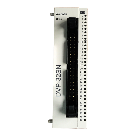
Introduction
1.1 Model Explanation & Peripherals
Thank you for choosing Delta DVP-Slim series programmable logic controller. DVP-Slim series pin-headed digital I/O
extension unit offers 32 points. For DVP-SS/SA/SX/SC series MPU, the maximum digital I/O extension points (including
the MPU) can reach 128 points. For SV series MPU, the maximum digial I/O extension points (including the MPU) can
reach 256 points. In addition, maximum 8 additional special modules (AD/DA/PT/TC/XA/PU) can be extended to
DVP-Slim series extension unit.
Nameplate Explanation
Delta PLC model name
Power input spec.
24Vdc 1W
Output point module spec.
0.1A(24VDC)POINT
Barcode & serial No.
Version
32SN11TNT7020001
VX.XXAX
Model Name
DVP series
Points (32 for output)
TN:
NPN transistor
N:
No output module
Module type
M:
Input point extension unit
N:
Output point extension unit
DC power input
1.2 Product Profile
Unit: mm
POWER, L.V (low voltage) indicator
Extension unit positioning hole
Model name
Nameplate
Extension unit fixing clip
Extension unit fixing clip
I/O terminals
DIN rail (35mm)
DIN rail clip
Connection port for extension unit
2007-01-23
1.3 Model Information
Power
Model name
supply Points
5011658300-MNE0
DVP32SM11N
24V DC
DVP32SN11TN
Specifications
2.1 Electrical Specifications
Model
Item
Power supply voltage
Motion specification
Power consumption
Insulation resistance
Noise immunity
Earth
Operation/storage
environment
Shock/vibration
immunity
Weight (g)
M A D E I N X X X X X
2.2 I/O Point Specifications
Serial No.
Input type
Input current
Production No.
Production week
Active level
Production year (2007)
Production plant
Response time
Model name
Circuit isolation /
operation instruction
Output type
Current specification
Voltage specification
Maximum load
Response time
Installation & Wiring
3.1 Terminals of Digital I/O Extension Unit
Input
Output
Dimension
Type
Points
Type
(mm)
DC Type
32
0
N/A
Sink/Source
25.2 90
(NPN)
0
N/A
32
Transistor
DVP32SM11N
DVP32SN11TN
24V DC (-15% ~ 20%) (with DC input polarity reverse protection)
Within 5ms of the momentary power loss, the device will keep on operating.
1W
1.5W
5 MΩ (all I/O point-to-ground: 500V DC)
>
ESD (IEC 61131-2, IEC 61000-4-2): 8KV Air Discharge
EFT (IEC 61131-2, IEC 61000-4-4): Power Line: 2KV, Digital I/O: 1KV,
Analog & Communication I/O: 1KV
Damped-Oscillatory Wave: Power Line: 1KV, Digital I/O: 1KV
RS (IEC 61131-2, IEC 61000-4-3): 26MHz ~ 1GHz, 10V/m
The diameter of grounding wire shall not be less than that of L, N terminal of the
power. (When many PLCs are in use at the same time, please make sure every PLC
is properly grounded.)
Operation: 0ºC ~ 55ºC (temperature); 50 ~ 95% (humidity); pollution degree 2
Storage: -40ºC ~ 70ºC (temperature); 5 ~ 95% (humidity)
International standards: IEC1131-2, IEC 68-2-6 (TEST Fc)/IEC1131-2 & IEC 68-2-27
(TEST Ea)
70g
70g
Input Point
DC (SINK or SOURCE)
24VDC, 5mA
Off
On more than 16V DC
On
Off less than 14.4V DC
Approx. 10ms, 0 ~ 15ms adjustable from D1020, D1021
By photocoupler / LED On
Output Point
Transistor – T (NPN)
0.1A/point
5 ~ 24 VDC
55ºC/1A (COM), 25ºC/2.4A (COM)
Off
On less than 0.1ms
On
Off less than 0.3ms
DVP32SM11N
DVP32SN11TN
1
2
X1
1
X0
Y0
3
4
X3
3
X2
Y2
X4
5
6
X5
Y4
5
X6
7
8
X7
Y6
7
X10
9
10
X11
Y10
9
10
X12
11
12
X13
Y12
11
12
X14
13
14
X15
Y14
13
14
Y16
X16
15
16
X17
15
16
S/S
17
17
18
S/S
GND
18
NC
19
20
NC
+24V
19
20
X20
21
22
X21
Y20
21
22
X22
23
24
X23
Y22
23
24
X24
25
26
X25
Y24
25
26
X26
27
28
X27
Y26
27
28
X30
29
30
X31
Y30
29
30
X32
31
32
X33
Y32
31
32
X34
33
34
X35
Y34
33
34
X36
35
36
X37
Y36
35
36
S/S
37
38
S/S
GND
37
38
NC
39
40
NC
+24V
39
40
DVP32SM
DVP32SN
DVP32SN currently only offers TN (NPN) transistor output.
Please be aware of the following PIN wiring methods for DVP32SN to prevent burn-down of the extension unit.
1. PIN19, PIN20, PIN39 and PIN40 can only connected to +24V DC. The 4 points have already been designed as
Outline
short-circuit within the extension unit; therefore only 1 of the points needs to be wired.
2. PIN17, PIN18, PIN37 and PIN38 can only connected to GND. The 4 points have already been designed as
short-circuit within the extension unit; therefore only 1 of the points needs to be wired.
3.2 Connection
60
Step 1: Screw open the side cover of the extension
unit and you will see the connection port.
Step 2: Lift the fixing clip by the screwdriver.
Step 3: Adjust the positioning hole of the MPU and
the extension unit and meet the connection port on
the MPU with the extension unit to tightly connect
the two.
Step 4: Fasten the fixing clip on the extension unit
to complete the connection.
3.3 Installation & Wiring
2
Y1
Install the PLC in an enclosure with sufficient space around it to allow heat dissipation as shown in the figure below.
4
Y3
6
Y5
8
Y7
Y11
Y13
Y15
Y17
GND
+24V
Y21
Y23
Y25
Y27
Y31
Y33
Y35
Y37
GND
+24V
D
DVP
D
D
MPU
D
D > 50mm
Advertisement

Subscribe to Our Youtube Channel
Related Manuals for Delta Electronics Programmablelogic Controller DVP-Slim


Summary of Contents for Delta Electronics Programmablelogic Controller DVP-Slim
- Page 1 2007-01-23 http://www.delta.com.tw/industrialautomation/ 5011658300-MNE0 Digital I/O Extension Unit (Pin Headed) Instruction Sheet Warning Please read this instruction sheet carefully before use. DVP-Slim is an OPEN-TYPE device and therefore should be installed in an enclosure free of airborne dust, humidity, electri shock and vibration. The enclosure should prevent non-maintenance staff from operating the device (e.g. key or specific tools are required to open the enclosure) in case danger and damage on the device may occur.
- Page 2 If abnormality is identified, check if the indicator and input circuit are normal by HPP/WPLSoft. Use of electronic switch with too much electricity leakage often results in unexpected actions of the input point.
Need help?
Do you have a question about the Programmablelogic Controller DVP-Slim and is the answer not in the manual?
Questions and answers