Chapters
Table of Contents
Troubleshooting

Related Manuals for Brother 1270N


Summarization of Contents
Brother Laser Printer Service Manual
Supported Printer Models
Identifies the specific printer models covered by this service manual.
Preface
Service Manual Contents and Purpose
Explains the manual's role in after-sales service and lists its chapters.
Chapter 1: General Information
Printer Features
Details the key features of the printer, such as resolution, print speed, and paper handling.
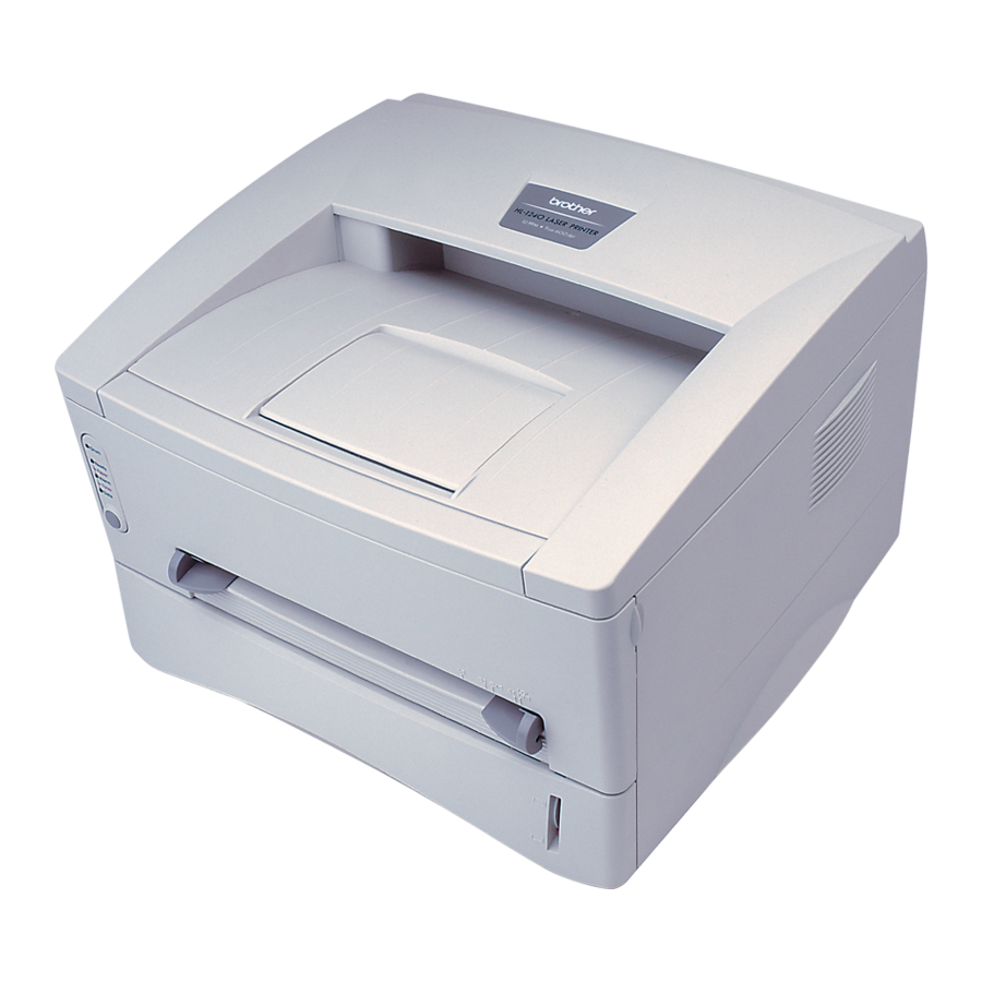
Printer Overview
Provides a visual and functional overview of the printer's front and rear components.
Printer Specifications
Lists technical specifications including printing method, resolution, speed, media, and developer.
Paper Handling Procedures
Explains how to load paper into the cassette and manually, including duplex printing.
Enhanced Memory Management
Explains the printer's data compression and memory capabilities for handling large documents.
USB Interface Support
Details the printer's compatibility and setup for USB connectivity on specific operating systems.
Network Features (HL-1270N)
Describes the network capabilities and connectivity options for the HL-1270N model.
Electrical and Mechanical Specifications
Lists power requirements, power consumption, noise levels, temperature, humidity, dimensions, and weight.
Network Specifications (HL-1270N)
Details network protocols, management, firmware updates, and supplied software for network models.
Paper Specifications
Covers feedable paper types and sizes for different input sources and cassette capacities.
Feedable Paper Types and Sizes
Lists specific paper types and sizes supported by the paper cassette and manual feed slot.
Paper Cassette Capacity
Specifies the maximum load height and paper feed conditions for the paper cassette.
Print Delivery Methods
Explains the output tray stacking capacity and straight paper path output.
Printing Area Specifications
Defines the effective printing area and the print guaranteed area of the printer.
Chapter 2: Installation and Basic Operation
Installation Requirements
Outlines necessary power supply, environmental conditions, and system requirements.
Printer Unpacking
Lists the components to check when unpacking the printer from its carton.
Printer Installation Guide
Guides users through the printer installation process, including driver setup.
Control Panel Operations
Explains the functions of the LEDs and control panel buttons for printer status and operation.
Windows System Requirements
Lists the minimum system requirements for installing and operating the Brother Printer Solution for Windows.
Printer Installation for Windows Users
Guides Windows users through the printer installation process using the CD-ROM.
Printer Installation without CD-ROM
Provides instructions for installing the printer driver from a floppy disk when a CD-ROM drive is unavailable.
Loading Paper into Cassette
Explains the procedure for loading normal paper and transparencies into the paper cassette.
Manual Paper Loading
Describes how to load envelopes, labels, organizers, and normal paper manually.
Manual Duplex Printing
Explains how to perform two-sided printing using manual duplexing from the cassette or manual feed.
Ready LED Indications
Details the status indicated by the Ready LED, including warming up, cooling down, and ready states.
Data (Toner) LED Indications
Explains the status indicated by the Data LED regarding print data processing and toner levels.
Drum LED Indications
Describes the meaning of the Drum LED, indicating the drum unit's end of life.
Alarm LED Indications
Explains when the Alarm LED blinks to indicate printer errors like cover open or memory full.
Control Panel Button Operations
Details the functions performed by the control panel button for operations like cancel printing and wake-up.
Other Control Features
Covers features like sleep mode and test print mode accessible via software or button operation.
Network Board Operation (HL-1270N)
Explains how to prepare and install the network board and its configuration utility.
Chapter 3: Theory of Operation
Electronics Overview
Presents general block diagrams of the printer's electronic systems for different models.
Mechanics Overview
Details the printing mechanism, including paper path, rollers, and key components.
Disassembly Procedures
Provides detailed, step-by-step instructions for disassembling various printer parts.
Printer Packing Procedure
Illustrates the materials and steps for packing the printer for shipment or storage.
Main PCB Block Diagrams
Shows block diagrams of the main PCB for HL-1030/1240, HL-1250, and HL-1270N models.
Main PCB Components
Details various components on the Main PCB, including ASIC, ROM, EEPROM, and reset circuits.
Engine PCB Function
Describes the function of the Engine PCB and the parts it controls.
BR-net PCB (HL-1270N)
Explains the BR-net PCB, its Ethernet controller, and its connection to the main PCB.
Power Supply Systems
Details the low-voltage and high-voltage power supply circuits and their regulated outputs.
Paper Transfer Process
Explains paper supply, registration, and the transfer of toner from the drum to the paper.
Printer Sensors
Describes the function of various sensors, including cover sensors and toner sensors.
Drum Unit Components
Details components of the drum unit such as the photosensitive drum, primary charger, and transfer roller.
Toner Cartridge Function
Explains how the toner cartridge develops the latent image to form a visible image.
Print Process Steps
Describes the charging, exposure, developing, transfer, and fixing stages of the print process.
Chapter 4: Disassembly and Re-assembly
Safety Precautions for Maintenance
Outlines critical warnings and cautions to follow before and during maintenance work.
Disassembly Flowchart
Presents a visual flowchart of the disassembly sequence for printer components.
Detailed Disassembly Procedures
Lists specific steps for disassembling individual parts like AC Cord, Drum Unit, etc.
Laser Unit Removal
Provides instructions for removing the laser unit, including precautions for handling optics.
Drive Unit Removal
Steps for removing the drive unit, including the main motor and development joint.
Fixing Unit Parts
Lists parts associated with the fixing unit, such as the heat roller and thermistor.
Printer Cover Parts
Lists various cover parts and labels for the printer.
Main PCB and Mask ROM Parts
Lists different versions of the Main PCB and Mask ROMs for various models.
Engine PCB Assemblies
Lists different part numbers for the Engine PCB, noting version differences.
Low-Voltage Power Supply PCB Parts
Lists parts for the low-voltage power supply unit, including inlet units and films.
High-Voltage Power Supply PCB Parts
Lists different versions of the high-voltage power supply PCB and associated screws.
AC Power Cords
Lists various AC power cords supplied with the printer for different regions.
Printer Accessories and Software
Lists printer drivers, setup guides, network setup guides, and other accessories.
Packing Materials
Lists the cartons, styrofoam pads, and bags used for packing the printer.
Network Board Parts
Lists parts for the network board, including the PCB and screws.
Adjusting Tools
Lists specialized tools like Torx screw drivers and grease for printer adjustment.
Chapter 5: Periodic Maintenance
Consumable Parts Information
Describes parts subject to deterioration and needing replacement, like Drum Unit and Toner Cartridge.
Periodical Replacement Parts
Lists parts requiring periodic replacement for maintaining product quality and their service life.
Periodical Cleaning Procedures
Details cleaning procedures for printer exterior, drum unit, scanner window, and electrical terminals.
Toner Cartridge Replacement
Provides a step-by-step guide for replacing the toner cartridge and cleaning the corona wire.
Cleaning the Printer Exterior
Instructions for cleaning the outside of the printer using a damp cloth.
Cleaning the Drum Unit
Steps for cleaning the drum unit, including the corona wire and returning the cleaner to home position.
Cleaning the Scanner Window
Procedure for gently wiping the scanner window with a soft dry cloth.
Cleaning Electrical Terminals
Instructions for cleaning electrical terminals inside the printer body for optimal performance.
MTBF and MTTR
Provides Mean Time Between Failure (MTBF) and Mean Time To Repair (MTTR) figures for the printer.
Chapter 6: Troubleshooting
Troubleshooting Introduction and Initial Checks
Guides on initial checks for operating environment, paper, consumable parts, and other issues.
Operator and Service Calls
Explains how to identify and resolve errors indicated by printer LEDs and calls for service.
Printer Error Messages
Lists error messages reported by the status monitor and their corresponding remedies.
Image Defect Troubleshooting
Provides examples of image defects and troubleshooting steps for common print quality issues.
Identifying Printer Problems
A flowchart to help identify the cause of a printer problem based on LED status or error messages.
Service Call Indications
Explains when the printer requires a service call and the initial troubleshooting steps.
Error Message Printout Troubleshooting
Lists error messages printed by the printer and the corrective actions to take.
Paper Loading Issues
Details common paper loading problems and their remedies, such as printer not loading paper.
Clearing Paper Jams
Provides step-by-step instructions for clearing jammed paper from the printer.
Paper Feeding Problems
Addresses issues like double feeding, wrinkles, creases, page skew, curl, and wave.
Software Setting Problems
Discusses issues arising from incorrect software or printer driver settings.
Printer Malfunctions
Lists various malfunctions with their possible causes, checks, results, and remedies.
Grounding Contact Locations
Shows diagrams illustrating the location of grounding contacts on the drum unit and printer body.
Incorrect Printout Troubleshooting
Addresses issues where the printed output is incorrect or garbled compared to the PC screen.
Network Problems (HL-1270N)
Guides on troubleshooting network connectivity and printing issues for the HL-1270N.
Appendix 1: Serial Number Descriptions
Serial Number Interpretation
Explains how to interpret the numbers on printer and part labels for production month and factory ID.
Appendix 2: Roller Diameter and Circumference
Roller Diameter and Circumference List
Provides a table listing the diameter and circumference of various printer rollers.
Appendix 3: Print Speeds by Settings
Print Speed Variations
Details print speeds based on media type, size, and model, including notes on temperature effects.
Appendix 4: Drum Unit Life and Page Counter
Print Configuration for Drum/Page Count
Explains how to print the configuration page to check drum unit life and page count.
Test Print for Drum/Page Count (HL-1030)
Explains how to print the test page to check drum unit life and page count for HL-1030.
Reading Drum Unit Life
Explains how to interpret the drum unit life bar and calculate its remaining life.
Appendix 5: Using Self-Diagnostics Tools
Troubleshooting "Printer Won't Print" Tool
Instructions on using the tool to resolve issues like "printer can't print" or "garbage/incorrect fonts".
Diagnostics Tool Usage
Guides on using the diagnostics tool to report PC environment for problem investigation.
Printer Information Tool
Explains how to view printer information like version, page counter, and drum counter via software.
Appendix 6: NVRAM Default Values
NVRAM Default Values
Lists default values for key NVRAM settings, including drum LED timing and fixing temperature.
Appendix 7: Paper Cassette Information (Europe)
Paper Cassette Information (Europe)
Provides specific details about paper cassettes intended for the European market.
Appendix 8: Connection Diagram (HL-1030/1240)
Connection Diagram (HL-1030/1240)
Illustrates the electrical connections between the main PCB, engine PCB, LVPS, HVPS, and other units.
Appendix 9: Connection Diagram (HL-1250)
Connection Diagram (HL-1250)
Shows the electrical connections for the HL-1250 model, including interface options.
Appendix 10: Connection Diagram (HL-1270N)
Connection Diagram (HL-1270N)
Displays the electrical connections for the HL-1270N model, including the network board.
Appendix 11: Main PCB Circuit Diagram (HL-1030/1240) - Part 1
Main PCB Circuit Diagram (HL-1030/1240) - Part 1
Detailed circuit diagram of the Main PCB for HL-1030/1240, covering specific sections.
Appendix 12: Main PCB Circuit Diagram (HL-1030/1240) - Part 2
Main PCB Circuit Diagram (HL-1030/1240) - Part 2
Continuation of the Main PCB circuit diagram for HL-1030/1240, detailing further components.
Appendix 13: Main PCB Circuit Diagram (HL-1250/1270N) - Part 1
Main PCB Circuit Diagram (HL-1250/1270N) - Part 1
First part of the Main PCB circuit diagram for HL-1250/1270N models.
Appendix 14: Main PCB Circuit Diagram (HL-1250/1270N) - Part 2
Main PCB Circuit Diagram (HL-1250/1270N) - Part 2
Second part of the Main PCB circuit diagram for HL-1250/1270N models.
Appendix 15: Main PCB Circuit Diagram (HL-1250/1270N) - Part 3
Main PCB Circuit Diagram (HL-1250/1270N) - Part 3
Third part of the Main PCB circuit diagram for HL-1250/1270N models.
Appendix 16: Main PCB Circuit Diagram (HL-1250/1270N) - Part 4
Main PCB Circuit Diagram (HL-1250/1270N) - Part 4
Fourth part of the Main PCB circuit diagram for HL-1250/1270N models.
Appendix 17: Main PCB Circuit Diagram (HL-1250/1270N) - Part 5
Main PCB Circuit Diagram (HL-1250/1270N) - Part 5
Fifth part of the Main PCB circuit diagram for HL-1250/1270N models.
Appendix 18A: Engine PCB Circuit Diagram (Old Version)
Engine PCB Circuit Diagram (Old Version)
Circuit diagram for the older version of the Engine PCB.
Appendix 18B: Engine PCB Circuit Diagram (New Version)
Engine PCB Circuit Diagram (New Version)
Circuit diagram for the newer version of the Engine PCB.
Appendix 19: Network Board Circuit Diagram (HL-1270N)
Network Board Circuit Diagram (HL-1270N)
Circuit diagram for the Network Board used in the HL-1270N model.
Appendix 20: Low-Voltage Power Supply PCB Circuit Diagram (110-120V)
Low-Voltage Power Supply PCB Circuit Diagram (110-120V)
Circuit diagram for the low-voltage power supply PCB operating on 110-120V.
Appendix 21: Low-Voltage Power Supply PCB Circuit Diagram (220-240V)
Low-Voltage Power Supply PCB Circuit Diagram (220-240V)
Circuit diagram for the low-voltage power supply PCB operating on 220-240V.
Appendix 22A: High-Voltage Power Supply PCB Circuit Diagram (Old)
High-Voltage Power Supply PCB Circuit Diagram (Old)
Circuit diagram for the older version of the high-voltage power supply PCB.
Appendix 22B: High-Voltage Power Supply PCB Circuit Diagram (New)
High-Voltage Power Supply PCB Circuit Diagram (New)
Circuit diagram for the newer version of the high-voltage power supply PCB.
Appendix 23: Differences in HVPS & Engine PCB Versions
Differences in HVPS & Engine PCB Versions
Highlights differences between old and new versions of High-Voltage Power Supply and Engine PCBs.
Brother Laser Printer Parts Reference List
How to Use the Parts Reference List
Explains the format and information provided in the parts reference list for ordering.
Need help?
Do you have a question about the 1270N and is the answer not in the manual?
Questions and answers