Advertisement
Product Introduction
Product Description
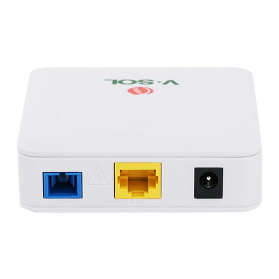
1GE Dual mode ONU meets telecom operators FTTO (office), FTTD (Desk), FTTH(Home) broadband speed, SOHO broadband access, video surveillance and other requirements and design EPON/GPON Gigabit Ethernet products. It is based on mature and stable, cost-effective EPON/GPON technology, high reliability, easy management, configuration flexibility and good quality of service (QoS) guarantees. They are fully compliant with GPON and EPON technical regulations such as ITU-T G.984.x, IEEE802.3ah and so on. Dual mode ONU can detect and exchange PON mode automatically.
Figure 1-1: 1GE Dual Mode ONU

Special features
Integrated auto detecting, auto configuration, and auto firmware upgrade technology.
Support OAM/OMCI remote configuration and maintenance.
Support rich VLAN, DHCP Server and IGMP snooping multicast feature.
Fully compatibility with OLT based on Broadcom/PMC/Cortina chipset.
Support NAT, Firewall function.
Support bridge and router mode.
Technical Parameter
| Technical items | Descriptions |
| PON interface | 1 G/EPON port(EPON PX20+ and GPON Class B+) Receiving sensitivity: ≤-28dBm Transmitting optical power: 0~+4dBm Transmission distance: 20KM |
| Wavelength | Tx1310nm, Rx 1490nm |
| Optical interface | SC/PC connector |
| Interface | 1* 10/100/1000Mbps auto adaptive Ethernet interfaces. Full /Half Duplex, RJ45 connectors. |
| Indicator | 3 indicators, SYS, LINK/ACT, REG. |
| Operating condition | -5℃~55℃,10%~90%(non-condenseing) |
| Storing condition | -30℃~60℃,10%~90%(non-condenseing) |
| Power supply | DC 12V, 0.5A |
| Power consumption | ≤4W |
| Dimension | 82mm×82mm×25mm(L×W×H) |
| Net weight | 0.08Kg |
Application chart
Figure 1-2: Application chart

Panel description
Interface/Button panel
Figure 1-3: Interface/Button panel

| Name | Function |
| PON | Connect to OLT by SC type fiber connector, single mode optical fiber cable. |
| LAN | Connect PC or other devices with Ethernet port by Cat5 cable, RJ-45 connector. |
| DC 12V | Connect with power adapter. DC 12V, 0.5A. |
| RST | Press RST button over 10 seconds, onu restores factory default and reboot. |
Indication Panel
Figure 1-4: Indication panel

| LED | Mark | Status | Description |
| Interface | LINK/ACT | ON | Port is connected properly (LINK). |
| Off | Port connection exception or not connected. | ||
| Blink | Port is sending or/and receiving data (ACT). | ||
| Registratio n | REG | ON | Green:the device is registered to PON system. |
| OFF | Device has received optical signal and not registered | ||
| Blink | Red:the Device does not receive optical signals. | ||
| System | SYS | On / Blink | System is not running or fatal error Normal running |
Quick Installation
Standard Packing Contents
When you received our product, please check carefully to make sure that our products whether have some defects or not. If something wrong with shipping, please contact carrier; other damage or lack of some parts, please contact with dealer.
| Contents | Quantity |
| Dual Mode ONU | 1 pcs |
| Power Adapter | 1 pcs |
| Installation Guide | 1 pcs |
Quick Installation
- Connecting the optical fiber cable to the unit.
- Remove the protective cap of the optical fiber.
- Clean the end of the optical fiber with an optical fiber end cleaner.
- Remove the protective cap of the ONU optical interface (PON interface). Connect the fiber to the PON port on the unit.
Note: When measuring the optical power before connecting to the ONU, it is recommended to use a PON Inline Power Meter.
While connecting, please note:
Keep the optical connector and the optical fiber clean.
Make sure there are no tight bends in the fiber and that the bending diameter is greater than 6cm. Otherwise, the optical signal loss may be increased, to the extent that signal may be unavailable.
Cover all optic ports and connectors with protective cap to guard against dust and moisture when the fiber is not used.
- Apply power to the unit. Push the power button.
- After the ONU is power ON, Indicators should light up as for normal operation. Check whether the PON interface status LED (PON) is on continuously. If it is, the connection is normal; otherwise there is either problem of the physical connection or the optical level at either end. This may be caused by either too much or too little attenuation over the optical fiber. Please refer to the Layout Description section of this installation manual for normal LED activity.
- Check all signal levels and services on all the ONU communication ports.
Unit Installation Adjustment
Installing the ONU on a horizontal surface (Bench top)
Put the ONU on a clean, flat, sturdy bench top. You must keep the clearance for all sides of the unit to more than 10cm for heat dissipation.
Installing the ONU on a vertical surface (Hanging on a wall)
You can install the ONU on a vertical surface by using the mounting holes on the bottom of the ONU chassis and two flat-head wood screws.
- Insert the screws into the wall. The screw positions must be in the same horizontal line and the distance between them must be 145mm. Reserved at least 6mm between the screw caps and the wall.
- Hang the ONU on the screws through the mounting holes.
Configuration
After finishing the basic connection configuration, you can use its basic function. In order to satisfy individuation service requirements, this charter provides the user parameter modification and individuation configuration description.
This model of ONU is designed as SFU(single family unit, bridge mode), there is no bridge mode WAN in ONU. When it works on bridge mode, VLAN of LAN port should be configured by OLT. When it works on router mode, you may configure through its web management.
Login
The device is configured by the web interface. The following steps will enable you to login:
- Conform "Quick Installation" to install;
- The device default IP is 192.168.1.1;
- Open your web browser, type the device IP in address bar;
- Entry of the user name and password will be prompted. Enter the default login user name and password.
By default, there are two user levels for management. Administration level user name is "admin", password is "stdONUi0i". Normal level user name is "user", password is "user".
Figure 3-1: Login

For security, you will be asked to modify password after you logged in by default password. The new password must meet the requirements that display on the webpage. After submitted, it requires you to login by new password.
Figure 3-2: Change Password


Status
This part shows the main information of product.
Device Information
This page shows the device basic information, such as Device Model, Hardware Version, Software Version, PON SN, PON mode and so on.
Figure 3-3: Device Information

Network Interface
WAN Connection
This page shows WAN connection information you have configured.
Figure 3-4: WAN Connection

PON Inform
This page shows the PON information, such as PON state, input power, output power, and optical module voltage, current, temperature.
Figure 3-5: PON Information

User Interface
This page shows the Ethernet port information, including port status, MAC address and statistics.
Figure 3-6: Ethernet Information

Network
Internet
This page allows user to configure router mode WAN connection. You can only configure route mode WAN connections here. The device default settings is bridge mode(without any WAN).
Figure 3-7: WAN Connection

| Parameter | Illustration |
| Connection Name | The list of WAN connection name that has been created. If you want to create a new WAN connection, please select "Create WAN Connection" and input other Parameter at the same time and then click "Create" button. If you want to edit WAN connection, please select the wan connect name you want to edit and change some Parameter and then click "Modify" button. If you want to delete one connection, please select the wan connection you want to delete and then click "Delete" button. |
| New Connection Name | Name of new connection that you want to create. | ||
| VLAN | Enable VLAN | Checked indicates the packets are transmitted by the PON port take VLAN tag. Unchecked indicates the packets are transmitted by the PON port don't take VLAN tag. | |
| VLAN ID | Input the VLAN ID you want to set. Range is 0~4094. Input 0 means don't use any VLAN. | ||
| 802.1P | Select VLAN priority you want to set. Range is 0~7. | ||
| Type | Bridge/Route. There is only Route mode can be selected. The device works on route mode with this WAN connection. If you want it to work on bridge mode, don't configure any WAN connection. | ||
| Service List | Service mode indicates what the wan connection is used for. There is only INTERET can be selected. | ||
| MTU | Max transfer unit. Default Value (in Byte): 1500(static/DHCP) or 1492(PPPoE). | ||
| Link Type | PPP/IP. PPP is used for PPPoE, and IP is used for static IP or DHCP. | ||
| PPP | Username | PPPoE account. | |
| Password | PPPoE password. | ||
| DMS name | Server name. | ||
| Authentication Type | PPPoE authentication type, including Auto, PAP and CHAP. | ||
| Connection Trigger | The trigger of PPPoE connection after disconnected. Always On: once PPPoE disconnected, ONU will connect again automatically. On Demand: ONU will connect again if there is data traffic. Manual: ONU will connect again after submitted the configurations. | ||
| IP Version | IPv4/IPv6 | ||
| Enable NAT | Checked indicates NAT function is enabled. Unchecked indicates NAT function is disabled. Only IPv4 has this option. | ||
| IP Type/PPP TransType | Method of WAN connection Obtains IP address. If link type is PPP, PPP TransType will be PPPOE; if link type is IP, IP Type will be static or DHCP. | ||
| IPv6 | IPv6 Info Get Mode | Method of WAN connection obtains IPv6 address, including Manual Mode and Auto Mode. | |
| GUA From | Method of WAN connection obtains Global Unique IPv6 Address. | ||
| DNSv6 From | Method of WAN connection obtains DNSv6. | ||
| Prefix Delegation From | Method of prefix delegation. | ||
LAN
This page supports the management of the ONU's IP address, dynamic address management, including dynamic address distribution and relevant parameters distribution, such as lease time, address range, DHCP Proxy, etc.
DHCP Server
This page contains LAN IPv4 address and LAN DHCP server configurations.
Figure 3-8: LAN IPv4 Address Settings

| Parameter | Illustration | ||
| LAN IP Address | LAN IPv4 address. | ||
| Subnet Mask | LAN IPv4 mask. | ||
| Enable DHCP Server | Switch of ONU DHCP server. | ||
| Start IP Address | The start IP address of DHCP IP pool. | ||
| End IP Address | The end IP address of DHCP IP pool. | ||
| DN | Assign ISP DNS | Checked indicates LAN DHCP will use ISP DNS. Unchecked indicates LAN DHCP use DNS that set in the textbox. | |
| DNS Server IP Address | DNS server addresses for LAN DHCP. | ||
| Default Gateway | Default gateway of LAN DHCP. It should be the same as LAN IPv4 IP address. | ||
| Lease Time | Lease time of the IP address. | ||
RA Service
This page show RA configuration.
Figure 3-9: RA Configuration

DHCP Server(IPv6)
This page contains LAN IPv6 address and LAN DHCP server configurations.
Figure 3-10: LAN IPv6 Address Settings

Prefix Management
This page is used to configure IPv6 prefix parameters.
Figure 3-11: Prefix Management

Port Service(Ipv6)
This page is used to configure DHCPv6 and RA function of LAN port.
Figure 3-12: Port Service(IPv6)
")
PON Settings
LOID
This page allows user to configure LOID and password which are used for registering to OLT.
Figure 3-13: LOID settings

SN
This page allows user to configure GPON SN and password which are used for registering to OLT.
Figure 3-14: GPON SN Settings

PON Mode
This page allows user to configure PON mode when connected to corresponding system.
AUTO: ONU will detect PON mode and shift to proper PON mode.
GPON: ONU will work on GPON mode.
EPON: ONU will work on EPON mode.
Figure 3-15: PON Mode

Routing(Ipv4)
Default Gateway
This page allows user to configure default gateway of ONU. Just need to specify the WAN connection that connected to the gateway.
Figure 3-16: Default Gateway

Static Routing
This page allows user to specify a WAN connection as the Route Interface, and then configure destination IP, mask and gateway.
Figure 3-17: Static Routing

| Parameter | Illustration |
| WAN Connection | Select WAN connection as static routing interface. |
| Network Address | Destination network address. |
| Subnet Mask | The Mask of destination network address. |
| Gateway | Gateway IP address of static routing. |
Routing Table
This page displays IP routing rules.
Figure 3-18: Routing Table

Security
Firewall
This page allows user to set anti-hacking protection and the level of the firewall (IPv4). User also can set custom firewall rules.
Figure 3-19: Firewall Level

| Parameter | Illustration |
| Enable Anti-Hacking Protection | Anti-Hacking Protection switch. |
| Firewall Level | Low: Allow all inner or outer hosts to access. Middle: Allow inner or outer hosts which are limited by the rules that have been created to access. High: Forbid ICMP Input, Forbid Port Scan, Denial of Service protections. |
Figure 3-20: Custom Firewall Rule

| Parameter | Illustration |
| IP Version | Select IPv4 or IPv6. |
| Name | Firewall rule name. |
| Enable | Enable or disable the rule. |
| Order | Order of the rule. |
| Protocol | Select protocol which the rule used for. There are only several protocols can be selected. |
| State | Select data traffic state. Suggest using ANY. |
| Source IP Address | Source IP address of traffic that matches the rule. |
| Source IP Mask | Mask of source IP address. |
| Start Source Port | Start source TCP or UDP port. The protocol must be TCP or UDP. |
| End Source Port | End source TCP or UDP port. The protocol must be TCP or UDP. |
| Destination IP | Destination IP address of traffic that matches the rule. |
| Address | |
| Destination IP Mask | Mask of destination IP address. |
| Start Destination Port | Start destination TCP or UDP port. The protocol must be TCP or UDP. |
| End Destination Port | End destination TCP or UDP port. The protocol must be TCP or UDP. |
| The direction of data flow | Direction of data flow that matches the rule. In the option, CPE indicates CPU of ONU. |
| Mode | Data forward mode of the rule, including discard and permit. |
Service Control
This page allows user to set IP filter rules.
Figure 3-21: Service Control

| Parameter | Illustration |
| IP Version | Select IPv4 or IPv6. |
| Enable | Enable or disable IP filter rule. |
| Ingress | Ingress interface of data traffic. |
| Start Source IP Address | Start source IP address of data traffic. |
| End Source IP Address | End source IP address of data traffic. |
| Mode | Data transfer mode, including discard or permit. |
| Service List | Service list for IP filter. |
User also can configure remote access port for different service, such as http and telnet.
Figure 3-22: Remote Access Port

MAC Filter
This page allows user to set the relevant parameters of the MAC filter function. The table will display the MAC Filter rules after setting completed.
Figure 3-23: MAC Filter

| Parameter | Illustration |
| Enable | Enable or disable the rule. |
| Mode | Data transfer mode, including discard or permit. |
| Type | Select ONU working mode that the rule takes effect. |
| Protocol | Select protocol of data traffic. |
| Source MAC Address | Source MAC address of data traffic. |
| Destination MAC Address | Destination MAC address of data traffic. |
Application
Multicast
IGMP Mode
This page allows user to enable or disable IGMP snooping.
Figure 3-24: IGMP Mode

Basic Configuration
This page allows user to configure IGMP basic configuration, including multicast aging time and non-fast leave.
Figure 3-25: IGMP Basic Configuration

VLAN Configuration
This page allows user to configure multicast VLAN for the port. If WAN VLAN is not the same as LAN VLAN, it means multicast VLAN will be translated.
Figure 3-26: Multicast VLAN

Tag Configuration
This page allows user to configure multicast VLAN untag mode.
Figure 3-27: Tag Configuration

Maximum Address Configuration
This page allows user to configure maximum multicast address.
Figure 3-28: Maximum Address Configuration

BPDU
This page allows user to enable or disable RSTP BPDU(Bridge Protocol Data Unit) forwarding.
Figure 3-29: BPDU Forwarding

DNS Service
Domain Name
This page allows user to configure domain name of ONU. Users can access ONU webpage by this domain name.
Figure 3-30: Domain Name

DNS
This page allows user to configure DNS server. DNS request will be sent to these DNS servers.
Figure 3-31: DNS

Port Forwarding
This page allows user to configure port forwarding.
Figure 3-32: Port Forwarding

| Parameter | Illustration |
| Enable | Enable or disable port forwarding rule. |
| Name | Name of the port forwarding rule. |
| Protocol | Protocol of the port forwarding rule, including TCP and UDP. |
| WAN Host Start/End IP Address | Specify WAN host IP range for the port forwarding rule. Only in the range, the host of WAN side can work with the rule. |
| WAN Connection | Select WAN connection. |
| WAN Start/End Port | TCP or UDP port range of WAN side host. |
| LAN Host IP Address | Specify host IP address of LAN side. |
| LAN Host Start/End Port | TCP or UDP port range of LAN side host. |
Administration
User Management
This page allows user to change password of current login username.
Figure 3-33: User Management

Login Timeout
This page allows user to set webpage login timeout. If don't operate the webpage for the time out, the account will logout automatically.
Figure 3-34: Login Timeout

System Management
This page allows user to reboot the device, restore factory default and restore backup configuration. The process of reboot will take several minutes.
Figure 3-35: System Management

Software Upgrade
This page allows user to update software of the device. Click the "Choose File" button to select the software and then click the "Update" button to update.
Figure 3-36: Software Upgrade

Configuration Management
This page allows user to backup and restore configuration.
Figure 3-37: Configuration Management

Diagnosis
PING Diagnosis
This page shows about the ping test. You can diagnose connection status between ONU and other devices.
Figure 3-38: PING Diagnosis

| Parameter | Illustration |
| IP Address or Host Name | Input the destination IP you want to ping. |
| Egress | Select the egress interface you want to ping. |
Mirror Configuration
This page allows user to set port mirror for troubleshooting. After configured port mirror, the traffic of WAN connection will be copied and sent to LAN port.
Figure 3-39: Port Mirror

| Parameter | Illustration |
| Source | Select WAN connection as mirrored interface. |
| Destination | The LAN port is mirroring interface. |
Loopback Detection
Basic Configuration
This page allows user to set basic parameters of loopback detection.
Figure 3-40: Basic Configuration

| Parameter | Illustration |
| Destination MAC | Select the destination MAC of loopback packet. |
| Ethernet Type | Set the Ethernet type of loopback packet. |
| Send Interval | Set sending Interval time of loopback packet. |
| Port Closing Time | Set how much time the port will be closed once detected loopback. |
| Loopback Recovery Time | Set loopback recovery time. |
Enable Configuration
This page allows user to enable or disable LAN port loopback feature.
Figure 3-41: Enable Configuration

| Parameter | Illustration |
| Loopback Enable | Enable or disable LAN port loopback detection. |
| Alarm Enable | Enable or disable LAN port loopback alarm. |
| Portdislooped Enable | Enable or disable LAN port automatic recovery. |
VLAN Configuration
This page allows user to set VLAN of loopback detection packet. After added VLAN, ONU will send out loopback detection packets with the VLAN.
Figure 3-42: VLAN Configuration

LED Control
This page allows user to turn off or turn on the LED indicators.
Figure 3-43: LED Control

Help
The Help information of ONU displays instruction and prompt of each web UI.
Figure 3-44: Help information

Documents / ResourcesDownload manual
Here you can download full pdf version of manual, it may contain additional safety instructions, warranty information, FCC rules, etc.
Advertisement

Need help?
Do you have a question about the ONU and is the answer not in the manual?
Questions and answers