Intex Krystal Clear C2500, FP634 Manual
- Owner's manual (111 pages) ,
- Owner's manual (56 pages) ,
- Owner's manual (19 pages)
Advertisement
- 1 PARTS REFERENCE
- 2 POOL OUTLET - STRAINER & PLUNGER VALVE SETUP (OPTIONAL)
- 3 POOL INLET - NOZZLE & PLUNGER VALVE SETUP (OPTIONAL)
- 4 FILTER PUMP HOSE CONNECTION SETUP
- 5 FILTER PUMP INSTALLATION DISTANCE
- 6 FILTER PUMP STATIONARY MOUNTING
- 7 OPERATING INSTRUCTIONS
- 8 OPERATING TIME TABLE
- 9 CLEANING OR REPLACING FILTER CARTRIDGE
- 10 POOL CARE AND CHEMICALS
- 11 LONG TERM STORAGE & WINTERIZATION
- 12 TROUBLESHOOTING GUIDE
- 13 COMMON POOL PROBLEMS
- 14 GENERAL AQUATIC SAFETY
- 15 IMPORTANT SAFETY RULES
- 16 Documents / Resources
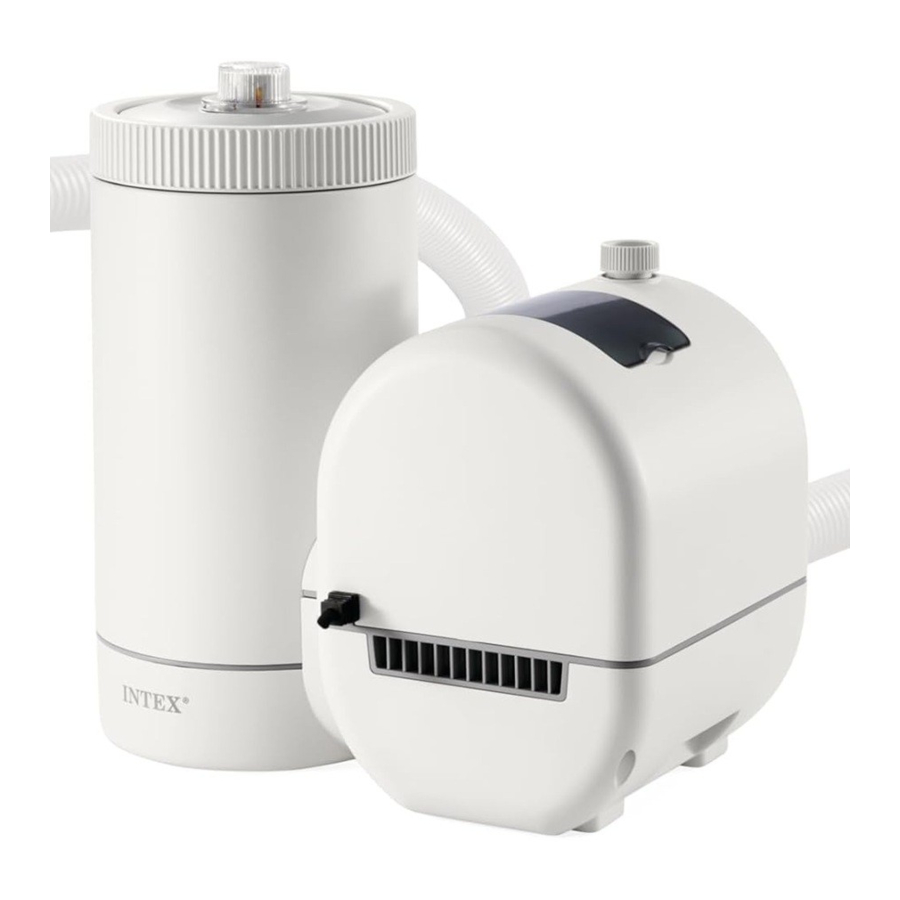
PARTS REFERENCE
Before assembling your product, please take a few minutes to check the contents and become familiar with all the parts.

 NOTE: Drawings for illustration purpose only. Actual product may vary. Not to scale.
| REF. NO. | DESCRIPTION | QTY. | SPARE PART NO. |
| 1 | THREADED FILTER HOUSING COLLAR | 1 | 13423 |
| 2 | FILTER GAUGE+AIR RELEASE VALVE | 1 | 13424 |
| 3 | VALVE O-RING | 1 | 13229 |
| 4 | FILTER HOUSING COVER | 1 | 13421 |
| 5 | FILTER HOUSING O-RING | 1 | 13422 |
| 6 | FILTER CARTRIDGE | 1 | 29005 |
| 7 | AIR RELEASE VALVE B (WITH O-RING) | 1 | 13425 |
| 8 | PUMP HOSE WITH NUTS | 2 | 11010 |
| 9 | SEDIMENT RELEASE VALVE | 1 | 13419 |
| 10 | HOSE O-RING | 2 | 13161 |
| 11 | VALVE O-RING | 1 | 10264 |
When ordering parts, be sure to quote the model number and part numbers.
If the pump was purchased individually, only these inlet fitting parts are included. No tools are required for the assembly.

Before assembling your product, please take a few minutes to check the contents and become familiar with all the parts.
If the pump was purchased as part of a pool set, below fitting parts are included.
Contact our Authorized Service Centers to order these parts if needed.
When ordering parts, be sure to quote the model number and part numbers.

NOTE: Drawings for illustration purpose only. Actual product may vary. Not to scale.
| REF. NO. | DESCRIPTION | QTY. | SPARE PART NO. | |
| Individually | Pool Set | |||
| 12 | STRAINER NUT | 1 | 2 | 10256 |
| 13 | FLAT STRAINER RUBBER WASHER | 1 | 2 | 10255 |
| 14 | THREADED STRAINER CONNECTOR | 0 | 1 | 10744 |
| 15 | ADJUSTABLE POOL INLET JET NOZZLE | 1 | 1 | 12369 |
| 16 | PLUNGER VALVE (HOSE O-RING & STEP WASHER INCLUDED) | 0 | 2 | 10747 |
| 17 | STRAINER GRID | 0 | 1 | 12198 |
| 18 | AIR JET VALVE | 1 | 1 | 12363 |
| 19 | INLET THREADED AIR CONNECTOR | 1 | 1 | 12371 |
| 20 | AIR JET VALVE CAP | 1 | 1 | 12373 |
| 21 | HOSE O-RING | 0 | 2 | 10262 |
| 22 | STEP WASHER | 0 | 2 | 10745 |
POOL OUTLET - STRAINER & PLUNGER VALVE SETUP (OPTIONAL)
The strainer grid prevents large objects from jamming and/or damaging the filter pump. The plunger valve assembly prevents water from flowing into the filter pump while the filter cartridge is being placed or cleaned. If your pool has inflatable top ring, install the strainer, nozzle and plunger valve before inflating the pool liner top ring. The parts numbers here onward, refer to the parts depicted in the Parts List section of this manual. To install, do the following:
- In a counter-clockwise motion unscrew plunger valve union from the threaded strainer connector (14) (see drawing 1). Be careful not to lose the step rubber washer (22). Place the plunger valve on the ground in a safe place.
![]()
- In a counter-clockwise motion unscrew the strainer nut (12) from the threaded connector (14). Leave the flat washer (13) on the connector (14).
- Install the strainer and plunger valve at the lower position of pool outlet (marked"+"). From the inside of the pool liner insert the connector (14) into one of the pre-cut holes with the washer remaining on the connector to be placed against the inside of the liner wall.
- Before assembly, lubricate the threads with a petroleum jelly. Then, with the flat side of the strainer nut (12) facing the outside wall of the liner in a clockwise motion screw the strainer nut (12) back onto the threaded connector (14) (see drawing 2).
![]()
- Finger tighten the strainer nut (12) onto the threaded connector (14).
- Grasp the plunger valve assembly. Make sure the step washer (22) is in place.
- In a clockwise motion screw the plunger valve union back onto the threaded connector (14) (see drawing 3).
![]()
- In a clockwise motion turn the plunger valve handle to close position. Ensure the plunger valve is securely closed. This will prevent water from flowing out during filling of the pool (see drawing 4).
![]()


POOL INLET - NOZZLE & PLUNGER VALVE SETUP (OPTIONAL)
- In a counter-clockwise motion unscrew plunger valve union from the inlet threaded air connector (19) (see drawing 5). Be careful not to lose the step rubber washer (22). Place the plunger valve on the ground in a safe place.
![]()
- In a counter-clockwise motion unscrew the strainer nut (12) from the inlet threaded air connector (19). Leave the flat washer (13) on the connector (19).
- Install the nozzle and plunger valve at the upper position of the pool inlet. From the inside of the pool liner insert the nozzle union (15 & 19) into one of the pre-cut holes with the washer remaining on the connector to be placed against the inside of the liner wall.
- Before assembly, lubricate the threads with a petroleum jelly. Then, with the flat side of the strainer nut (12) facing the outside wall of the liner in a clockwise motion screw the strainer nut (12) back onto the inlet threaded air connector (19) (see drawing 6).
![]()
- Finger tighten the adjustable pool inlet jet nozzle (15) and the strainer nut (12) onto the inlet threaded air connector(19).
- Grasp the plunger valve assembly. Make sure the step washer (22) is in place.
- Screw the air jet valve (18) over the inlet threaded air connector (19).
![warning]() NOTE: Make sure the air jet valve is securely tighten and facing up. In a clockwise motion screw the plunger valve union back onto the inlet threaded air connector (19) (see drawing 7).
NOTE: Make sure the air jet valve is securely tighten and facing up. In a clockwise motion screw the plunger valve union back onto the inlet threaded air connector (19) (see drawing 7).
![]()
- In a clockwise motion turn the plunger valve handle to close position. Ensure the plunger valve is securely closed. This will prevent water from flowing out during filling of the pool (see drawing 8).
![]()
- Adjust the direction of the nozzle head pointing away from the pool outlet for a better circulation result (see drawing 9).
![]()
- The pool liner is now ready to be filled with water. Consult the above-ground-pool owner's manual for the filling instructions.


NOTE: Do not cover the air jet valve (18) with the valve cap (20) under normal situation or when the pump is operating. See Troubleshooting Guide section for more details.
FILTER PUMP HOSE CONNECTION SETUP

- Remove the Krystal Clear® filter pump and hoses from the packaging.
- Place the filter pump in such a manner, that you can easily assemble the hose (8) connections to the plunger valve. Ensure the filter pump is accessible at all time for service and maintenance.
![warning]() Note: Some regional regulations may require the filter pump to be mounted on a stationary platform. There are two mounting holes located in the pump base for this reason. Consult your local authorities for filter pump mounting requirements.
Note: Some regional regulations may require the filter pump to be mounted on a stationary platform. There are two mounting holes located in the pump base for this reason. Consult your local authorities for filter pump mounting requirements. - Grasp the two pump hoses (8) and connect the hose nuts to the filter pump.
- In a counter-clockwise motion unscrew the threaded filter housing collar (1) from the filter housing. Place it in a safe place.
- The Filter Pump is an airtight system. In a counter-clockwise motion turn both air release valves (2 & 7) 1 - 2 turns to open. DO NOT remove air release valves as water will expel with force if the motor is turned on and injury may occur.
- Grasp and remove the filter housing cover (4). Check to see if a cartridge is inside the housing. If yes, replace the cover, finger tighten the housing collar (1) back onto the filter housing.
- Gently finger tighten the sediment release valve located at the bottom of the housing to be sure that water does not leak out.
- When the pool is filled connect the hose from the bottom of the filter housing to the highest strainer assembly. You will find the hose connection at the bottom of the plunger valve assembly. Use the hose nut to attach the hose.
- Connect the second hose which is fixed to the middle of the motor housing to the remaining liner connection.
It is essential to change any damaged element or set of elements as soon as possible. Use only parts approved by the manufacturer.

Position this product away from the pool, so as to prevent children from climbing on it and accessing the pool.
The installation instruction shall provide information on requirements specified for the electrical installation and shall include reference to national wiring rules.
FILTER PUMP INSTALLATION DISTANCE

(Generic layout of an electrical device relative to a swimming pool. Illustration not to scale)
According to the International Standard, IEC 60364-7-702, on electrical installation of swimming pools and other basins equipment, the following installation distances must be respected:
- The filter pump must be positioned more than 2m away from the pool walls.
- The power cord plug to the 220-240 volt electrical power source of the filter pump must be position more than 3.5 m away from the pool walls.
Check your local authorities to determine the appropriate standard and requirements for "electrical installation of swimming pools and basins equipment". The following table is for reference only:
| Country/Region | Standard Number |
| International | IEC 60364-7-702 |
| France | NF C 15-100-7-702 |
| Germany | DIN VDE 0100-702 |
| The Netherlands | NEN 1010-702 |
FILTER PUMP STATIONARY MOUNTING
Some countries, especially in the European community, require the filter pump to be secured to the ground or to a base in a permanent upright position. Check your local authorities to determine if there is a regulation in your area regarding above-the-ground swimming pool filter pumps. If yes, then the filter pump can be mounted to a platform using the hole located in the base. See drawing below.
The filter pump can be mounted on a cement base or onto a wooden platform to prevent accidental falling over. Total assembly must exceed 18kg.

OPERATING INSTRUCTIONS
- Make sure the filter pump is switched off. The switch is located on the motor housing.
- Connect the power cord to a GFCI protected electrical outlet.

Risk of electric shock. Connect this product only to a grounding type receptacle protected by a ground-fault circuit interrupter (GFCI) or residual current device (RCD). Contact a qualified electrician if you cannot verify that the receptacle is protected by a GFCI/RCD. Use a qualified electrician to install the GFCI/RCD, which has a maximum rate of 30mA. Do not use a portable residual current device (PRCD).

To prevent air lock, open the lower plunger valve (connected inlet hose) first and then the upper plunger valve (connected outlet hose). Open the air release valves, wait until water starts to flow out of the air release valves, close air release valves.
- Turn both plunger valve handles fully counter-clockwise until they stop. This opens the valve, allowing water to flow into the filter pump.
- With water flowing into filter pump, the water pressure will allow the air trapped inside to escape from the air release valves (2 & 7). When all the air has escaped water will flow out of the valves (2 & 7). When this occurs gently finger tighten the valves(2 & 7) in a clockwise direction.
- To operate the pump, see next page "Operating the system under TIMER mode or manually" section.

- Never put pool chemicals directly into the filter pump. This may damage the pump and void the warranty.

Operating the system under "TIMER" mode or manually:
To operate the filter pump under "TIMER" mode:
- Activate the unit:
Press![]() button. Flashing code "00" appears on the LED display, indicating that the unit is ready to be programmed.
button. Flashing code "00" appears on the LED display, indicating that the unit is ready to be programmed. - Set operating hours:
With code "00" flashing, press![]() button to set the desired operating hours. See the "Operating Time Table" for the required operating hours related to each pool size. Pressing
button to set the desired operating hours. See the "Operating Time Table" for the required operating hours related to each pool size. Pressing ![]() will increase the time from 01 to 12 hours maximum. If you have selected too many hours keep pressing
will increase the time from 01 to 12 hours maximum. If you have selected too many hours keep pressing ![]() to repeat the cycle.
to repeat the cycle.

The built-in timer will now activate the filter pump, at the same time each day, for the number of hours you have set. - Lock keypad controls:
With the desired hours showing, press![]() button until you hear a "beep" to lock the control buttons.
button until you hear a "beep" to lock the control buttons.
![warning]() NOTE: If you forget to lock the keypad controls, the system will automatically lock it and start working 10 seconds later.
NOTE: If you forget to lock the keypad controls, the system will automatically lock it and start working 10 seconds later.
The filter pump is now filtering the water and will stop after the operating hours are completed. - Readjust operating time if necessary:
The operating hours can be re-adjusted if necessary. Press![]() button until you hear a "beep" to unlock the keypad and the current programmed time will flash. Repeat steps 2 to 3.
button until you hear a "beep" to unlock the keypad and the current programmed time will flash. Repeat steps 2 to 3. - Stand-by/power saving mode:
- When the cycle ends, the LED display shows "00". The system is now in Stand-By mode. After 5 minutes the system goes into Power Saving mode and the LED display shows ".". The system will automatically turn itself back on in 24 hours.
- While the system is in Power Saving mode, press any button and the system will briefly display the programmed time and then "00".


To view the TIMER preset hours:
While the pump is operating, press ![]() button, the display will briefly flash the preset hours for 10 seconds and then display back the remaining operating hours.
button, the display will briefly flash the preset hours for 10 seconds and then display back the remaining operating hours.
To operate the filter pump manually (without the "TIMER" mode):
- To run the pump alone without the "Timer", press
![]() button to turn on the pump, then press
button to turn on the pump, then press ![]() button until the LED displays "FP", this indicates that the TIMER is off and the pump is now operating continuously.
button until the LED displays "FP", this indicates that the TIMER is off and the pump is now operating continuously. - To stop the pump, press
![]() button again.
button again.
![]()
 button until the LED displays "FP", this indicates that the TIMER is off and the pump is now operating continuously.
 button again.
OPERATING TIME TABLE
This table shows the required operating time for average use of the filter pump with AGP's. The filter pump running time should be 1 hour longer than the required operating time of the Saltwater System.
| Pool Size | Water Capacity (Calculated at 90% for Frame Pool and 80% for Easy Set & Oval Pool) | Recommend operating hours per day | ||
| (Gals) | (Liters) | (Hours) | ||
| INTEX ABOVE GROUND POOLS (AGP's) | ||||
| EASY SET® POOL | 18ʹ x 42ʺ (549cm x 107cm) | 4,786 | 18,115 | 4 |
| 18ʹ x 48ʺ (549cm x 122cm) | 5,455 | 20,647 | 4 | |
| CIRCULAR | 18ʹ x 48ʺ (549cm x 122cm) | 6,423 | 24,311 | 4 |
| METAL FRAME POOL | 24ʹ x 52ʺ (732cm x 132cm) | 12,481 | 47,241 | 6 |
| ULTRA/XTR FRAME POOL | 16ʹ x 48" (488cm x 122cm) | 5,061 | 19,156 | 4 |
| 18ʹ x 48ʺ (549cm x 122cm) | 6,423 | 24,311 | 4 | |
| 18ʹ x 52ʺ (549cm x 132cm) | 6,981 | 26,423 | 4 | |
| 20ʹ x 48ʺ (610cm x 122cm) | 7,947 | 30,079 | 4 | |
| 22ʹ x 52ʺ (671cm x 132cm) | 10,472 | 39,637 | 6 | |
| 24ʹx52" (732cm x 132cm) | 12,481 | 47,241 | 6 | |
| 26ʹ x 52ʺ (792cm x 132cm) | 14,667 | 55,515 | 8 | |
| GRAPHITE GRAY PANEL POOL SET™ | 15ʹ8ʺ x 49ʺ (478cm x 124cm) | 4,440 | 16,805 | 4 |
| 16ʹ8" x 49" (508cm x 124cm) | 5,061 | 19,156 | 4 | |
| 18ʹ8" x 53" (569cm x 135cm) | 6,981 | 26,423 | 4 | |
| OVAL FRAME POOL | 20ʹ x 12ʹ x 48ʺ (610cm x 366cm x 122cm) | 4,393 | 16,628 | 4 |
| RECT. ULTRA FRAME POOL | 15ʹ x 9ʹ x 48ʺ (457cm x 274cm x 122cm) | 3,484 | 13,187 | 2 |
| 18ʹ x 9ʹ x 52ʺ (549cm x 274cm x 132cm) | 4,545 | 17,203 | 4 | |
| 20ʹ x 10ʹ x 52ʺ (610cm x 305cm x 132cm) | 5,611 | 21,238 | 4 | |
| 24ʹ x 12ʹ x 52ʺ (732cm x 366cm x 132cm) | 8,403 | 31,805 | 4 | |
| 32ʹ x 16ʹ x 52ʺ (975cm x 488cm x 132cm) | 14,364 | 54,368 | 8 | |
CLEANING OR REPLACING FILTER CARTRIDGE
It is recommended that the filter cartridge be replaced at least every 2 weeks or as needed. Regularly monitor the filter clogging level.
The filter pump is equipped with a filter gauge, which indicates when to clean or replace the filter cartridge:
- Green zone: the filter cartridge is clean, no need to clean or replace.
- Yellow zone: the filter cartridge is dirty; it needs to be cleaned.
- Red zone: the filter cartridge is excessively dirty; it shall be cleaned or replaced.
![]()

NOTE: To ensure a correct filter gauge reading, remove any accessories (skimmer, lights, sprayer, auto cleaner, etc) from the filtration system inlet and outlet line. See "Troubleshooting Guide" section for details.
When the pump is not running (stand by mode) or OFF, the filter gauge indicator is in the green zone. You must activate the filter pump to see the last filter gauge indicator status.
The following steps provide instructions on how to clean or replace the filter cartridge.
- Make sure the filter pump is turned off, then disconnect the power cord from the electrical outlet.
- Turn both plunger valve handles fully clockwise until they stop. This closes the valve, prevents the water from flowing out of the pool.
- Gently turn the top air release valve once or twice in a counter-clockwise direction. The housing cover can now be easily removed.
- In a counter-clockwise direction remove the filter housing collar (1). Place it in a safe location.
- Remove the housing cover (4).
- Remove the used filter cartridge and use a strong pressure garden hose to rinse it clean. Replace with a new filter cartridge when it is discolored, deformed, has small holes and tears or as needed.
- Examine the inside of the filter housing.
- If dirt or sediment is located on the bottom of the housing then:
- In a counter-clockwise motion gently unscrew and remove the sediment valve(9) located at the bottom of the housing. Place it in a safe place.
- With a bucket of water or a garden hose pour water into the housing flushing out the sediment.
- Screw back the sediment valve(9) in a gentle clockwise motion. Do not over-tighten.
- Place a clean or new cartridge filter in the housing. Only use the original Intex cartridge for replacement. See "Parts Reference" section for detail.
- Return the housing cover (4) to its position and in a clockwise direction rescrew the housing collar (1) onto the filter housing.
- Turn both plunger valve handles fully counter-clockwise until they stop. This opens the valve, allowing water to flow into the filter pump.
- When the trapped air has escaped through the air release valves gently retighten the valves (2 & 7) in a clockwise direction.
- Reconnect the power cord.
- Turn on the pump.
- Check the inlet and outlet openings regularly to ensure they are not obstructed thus preventing a good filtration.
- The disposal of any used filter media should be in accordance with applicable local regulation and legislation.
POOL CARE AND CHEMICALS
- All pools require care to keep the water clear and hygienically clean. With proper chemical control, your filter will help attain this objective. Consult your pool supply dealer for instructions regarding the proper use of chlorine, algaecide and other chemical agents required for sparkling clear water.
- Keep pool chemicals away from children.
- Do not replenish chemicals in pool while pool is occupied. Skin or eye irritations could occur.
- Daily pH checking and chemical treatment of the water is very important and can not be overemphasized. Chlorine, algaecide and maintenance of proper pH levels are required when filling the pool as well as during the season. Consult your local swimming pool supply store for instructions.
- The season's first filling of the pool may have brackish water requiring extra water additives and extra filter changes. Do not allow swimming in pool until the pH level is balanced. Consult your local swimming pool supply store for instructions.
- Keep spare filter cartridges on hand. Replace cartridges every two weeks.
- Chlorinated water may damage lawns, gardens or shrubbery as children play in the pool and splash water outside the pool. Lawn areas underneath the pool liner will be destroyed.
![warning]() Note that some types of grass may grow through the liner.
Note that some types of grass may grow through the liner. - Filter run time depends on pool size, weather and usage level. Experiment with various run times so as to produce clean clear water.
- European standard EN16713-3 lists some additional pool water quality and water treatment information that can be found at www.intexcorp.com/support.

Concentrated chlorine solutions may damage the pool liner. Always follow the chemical manufacturer's directions, and the health and hazard warnings.
LONG TERM STORAGE & WINTERIZATION
- Before emptying your pool for long term storage, or relocation, be sure the water is directed towards an acceptable drain water receptacle away from the house. Check local regulations for specific directions regarding disposal of swimming pool water.
- Disconnect power cord from electrical outlet.
- Now, drain the pool.
- When the pool is empty, disconnect all hoses from pump and plunger valves and remove the strainers from the pool wall.
- Drain all water from the filter pump.
- Leave filter pump pieces & hoses outside to thoroughly air dry.
- Remove both plunger valves from the connectors (14 & 19). Be careful not to lose the step rubber washer (22).
- Coat the following O-rings and washers with petroleum jelly for long term storage:
- Air release valve & sediment O-rings (3 & 11).
- Filter housing cover O-ring (5).
- Pump hose O-rings (10 & 21).
- Strainer valve assembly step washers (22).
- Flat strainer rubber washers (13).
- Discard the used filter cartridge. Put aside 1 or 2 new cartridges for next season's use.
- It is best to place all dry pieces in the original packaging for storage or place them in an airtight plastic bag.
- Store the unit and accessories in a dry place. The storage's temperature should be controlled, between 32 degrees Fahrenheit (0 degrees Celsius) and 104 degrees Fahrenheit (40 degrees Celsius) storage location.
TROUBLESHOOTING GUIDE
| TROUBLE | CAUSE | SOLUTION |
| FILTER MOTOR FAILS TO START |
|
|
| FILTER DOESN'T CLEAN POOL |
|
|
| FILTER DOESN'T PUMP WATER OR THE WATER FLOW IS VERY SLOW |
|
|
| PUMP DOESN'T WORK |
|
|
| TOP COVER LEAKING |
|
|
| HOSE LEAKING |
|
|
| AIR LOCK |
|
|
| INLET THREADED AIR CONNECTOR / AIR JET VALVE LEAKING |
|
|
| SMALL LEAK FROM AIR JET VALVE WHEN PUMP IS ON |
|
|
| FOG OR MOISTURE INSIDE THE FILTER GAUGE WINDOW |
|
|
| FILTER CARTRIDGE IS DIRTY, BUT THE INDICATOR IS IN THE GREEN ZONE |
|
|
| AFTER CLEANING THE CARTRIDGE, THE INDICATOR IS STILL IN THE YELLOW ZONE |
|
|
| FILTER CARTRIDGE SEEMS CLEAN, BUT THE INDICATOR IS IN THE RED ZONE |
|
|
| TIMER IS INACCURATE OR TIMER CAN'T BE SET |
|
|
COMMON POOL PROBLEMS
| PROBLEM | DESCRIPTION | CAUSE | SOLUTION |
| ALGAE |
|
|
|
| COLORED WATER |
|
|
|
| FLOATING MATTER IN WATER |
|
|
|
| CHRONIC LOW WATER LEVEL |
|
|
|
| SEDIMENT ON POOL BOTTOM |
|
|
|
| SURFACE DEBRIS |
|
|
|
If you continue to experience difficulty, please contact our Consumer Service Department for assistance. See separate "Authorized Service Centers" sheet.
GENERAL AQUATIC SAFETY
Water recreation is both fun and therapeutic. However, it involves inherent risks of injury and death. To reduce your risk of injury, read and follow all product, package and package insert warnings and instructions. Remember, however, that product warnings, instructions and safety guidelines cover some common risks of water recreation, but do not cover all risks and or dangers.
For additional safeguards, also familiarize yourself with the following general guidelines as well as guidelines provided by nationally recognized Safety Organizations:
- Demand constant supervision. A competent adult should be appointed as a "lifeguard" or water watcher, especially when children are in and around the pool.
- Learn to swim.
- Take the time to learn CPR and first aid.
- Instruct anyone who is supervising pool users about potential pool hazards and about the use of protective devices such as locked doors, barriers, etc.
- Instruct all pool users, including children what to do in case of an emergency.
- Always use common sense and good judgement when enjoying any water activity.
- Supervise, supervise, supervise.
IMPORTANT SAFETY RULES
Read, Understand and Follow All Instructions Carefully Before Installing and Using this Product.
READ AND FOLLOW ALL INSTRUCTIONS
- Always supervise children and those with disabilities.
- Children must stay away from this product and electrical cord(s).
- Children shall not play with the appliance. Cleaning and user maintenance shall not be made by children without supervision.
- This appliance can be used by persons with reduced physical, sensory or mental capabilities or lack of experience and knowledge if they have been given supervision or instruction concerning use of the appliance in a safe way and understand the hazards involved.
- Assembly and disassembly by adults only.
- Risk of electric shock. Connect this product only to a grounding type receptacle protected by a ground-fault circuit interrupter (GFCI) or residual current device (RCD). Contact a qualified electrician if you cannot verify that the receptacle is protected by a GFCI/RCD. Use a qualified electrician to install the GFCI/RCD, which has a maximum rate of 30mA. Do not use a portable residual current device (PRCD).
- Always unplug this product from the electrical outlet before removing, cleaning, servicing or making any adjustment to the product. Always disconnect the appliance from the supply before assembling, disassembling or cleaning.
- The plug must be accessible after product is installed.
- Do not bury the electrical cord. Locate the cord where it will not be damaged by lawn mowers, hedge trimmers and other equipment.
- If the supply cord is damaged, it must be replaced by the manufacturer, its service agent or similarly qualified persons in order to avoid a hazard.
- To reduce the risk of electric shock, do not use extension cords, timers, plug adaptors or converter plugs to connect unit to electric supply; provide a properly located outlet.
- Do not attempt to plug in or unplug this product while standing in water or when your hands are wet.
- Keep this product more than 2m away from the pool.
- Keep this product more than 3.5m away from the pool (for France only).
- Keep the plug of this product more than 3.5m away from the pool.
- Position this product away from the pool, so as to prevent children from climbing on it and accessing the pool.
- Do not operate this product when pool is occupied.
- This product is for use with storable pools only. Do not use with permanently installed pools. A storable pool is constructed so that it may be readily disassembled for storage and reassembled to its original configuration.
- The appliance is intended only for household use.
- This product shall not be left outside during freezing weather conditions as it is not protected against the effect of freezing temperature.
- This product is intended to be used only for the purposes described in the manual!
FAILURE TO FOLLOW THESE WARNINGS MAY RESULT IN PROPERTY DAMAGE, ELECTRIC SHOCK, ENTANGLEMENT OR OTHER SERIOUS INJURY OR DEATH.
These product warnings, instructions and safety rules provided with the product represent some common risks of water recreation devices and do not cover all instances of risk and danger. Please use common sense and good judgement when enjoying any water activity.
Documents / Resources
References
Download manual
Here you can download full pdf version of manual, it may contain additional safety instructions, warranty information, FCC rules, etc.
Advertisement


Need help?
Do you have a question about the Krystal Clear C2500 and is the answer not in the manual?
Questions and answers