Advertisement
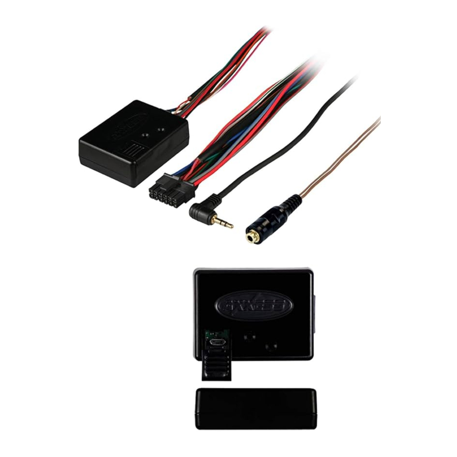
- 1 ASWC-1 Connections
- 2 Vehicle Connector
- 3 Initial Installation
- 4 Programming
- 5 LED Feedback
- 6 Connected Wires (Long Green LED)
- 7 Radio Type(Red LED)
- 8 Universal 3.5 Jack Connections
- 9 Radios with a single SWC wire
- 10 Universal 2 wire radios
- 11 Universal 3 wire radios
- 12 Operation
- 13 ASWC-1 Button Remapping
- 14 Button Assignment Legend
- 15 ASWC-1 Changing Radio Type
- 16 Radio Type List
- 17 Troubleshooting
- 18 Dual Assignment Instructions
- 19 Dual Assignment Legend
- 20 Documents / Resources
ASWC-1 Connections
- Connect the Black wire of the ASWC-1 and the wire in Pin 19 of the vehicle's radio harness shown, to Chassis Ground.
- Connect the Red wire of the ASWC-1 to 12v accessory power.
- Connect the Black/Green wire of the ASWC-1 to the wire in Pin 9 of the vehicle's radio harness shown.
- Connect the 3.5mm jack to the SWC input on the back of the radio. If the radio does not have a 3.5mm built in, please refer to wiring instructions for the Axxess 2 wire adapter.
ASWC-1 Resistive Wire Used:
Black/Green
Programming Method:
Auto-Detect
(No additional actions required)
Vehicle Connector

This is the view of the radio connector in the vehicle
Note: Wire colors may vary between vehicles but pin locations remain the same

Initial Installation
The first time the ASWC-1 is cycled on, the LED will begin to "Rapid Flash".
Programming
When the ASWC-1 begins to flash rapidly, it is in auto-detect mode, at this time do not press any buttons. The rapid flash will go out after
several seconds, then simply wait until the LED goes solid. If it does not go solid, see the "LED Feedback" section for information on how to proceed.
**NOTE - If you cycle the ignition on and the ASWC only shows one Green flash, press and hold the
Reset button for 3 seconds. This will force the ASWC1 into Rapid flash/Program mode. If the ASWC-1 goes to a slow Green/Red flash you held the reset button too long, repeat the 3 second press again.
LED Feedback
- Rapid LED flash Red/Green between 3-5 seconds
- Pause for 1-2 seconds
- Series of 7 Green LED flashes. (The ASWC-1 is detecting wires connected to the vehicle)
- Pause for 1-2 seconds
- Series of up to 18 Red LED flashes (The ASWC-1 is detecting the radio. List of radios)
After this sequence one of two things will happen. Either the LED will go solid Red, which means the ASWC-1 has detected the vehicle, or the ASWC-1 will go back to a slow Red/Green flash. This means the ASWC-1 did not detect the vehicle, and connections should be rechecked, or programming method should be verified.
Additional LED information:
After the ASWC-1 stops rapid flashing, it will pause then go directly to 7 Green flashes. Short flashes
indicate wires that are not connected, Long flashes indicate wires that are connected. *NOTE – The ASWC always flashes Green 7 times, this is an indicator of the ASWC-1 wires. After the green flashes, it will pause then go to Red flashes; the number of flashes depends on the radio you are installing.
Connected Wires (Long Green LED)
1st LED = White/Green wire on the ASWC-1
2nd LED = Yellow/Green wire on the ASWC-1
3rd LED = Green/Orange wire on the ASWC-1
4th LED = Gray/Red wire on the ASWC-1
5th LED = Black/Green wire on the ASWC-1
6th LED = Gray/Blue wire on the ASWC-1
7th LED = Pink or Blue/Pink wire on the ASWC-1
Note: Quick green flash indicated wires NOT connected.
Radio Type(Red LED)

Notes:
- If no SWC, change the radio type to the opposite radio type.
- If the interface shows JVC, change the radio type to Kenwood.
- If the interface shows Alpine, but an Alpine radio isn't installed, make sure the 3.5mm jack is plugged in.
- AX-SWC-PARROT required (sold separately). The software in the radio must be 2.1.4 or higher.
Universal 3.5 Jack Connections

Some radios will have a 3.5mm port located on the
back of the radio. For radios with this option, plug the male 3.5mm jack directly into the back of the radio.
For radios that don't come with a 3.5mm port in the radio, they will have their SWC wires pinned in the harness.
Typically when going through troubleshooting and programming on an ASWC-1 you can determine if you are having a vehicle or a radio issue. If the LED on the
ASWC-1 is going solid Red at the end of programming, the ASWC-1 is programmed to the vehicle. You're focus will now be on the radio.
Radios with a single SWC wire
Connect only the Brown wire to the radios SWC (Steering Wheel Control) wire. *Note: Kenwood & JVC radios sometimes list their SWC wire as a "Marine Remote". Refer to your radio manual if you are unsure. "Typically" single wire radios will auto detect as a Kenwood, or need to be force programmed to a Kenwood radio type (Refer to Radio Type Change ). There are times this isn't the case. In those instances, please call Tech Support.
Universal 2 wire radios
Connect the steering wheel control wire, referred to as Key-A or SWC-1, to the Brown wire of the connector. Then connect the remaining steering wheel control wire, referred to as Key-B or SWC-2, to the Brown/White wire of the connector.
Universal 3 wire radios
Connect the steering wheel control wire, referred to as Key-A or SWC-1, to the Brown wire of the connector. Then connect the remaining steering wheel control wire, referred to as Key-B or SWC-2, to the Brown/White wire of the connector. At first, connect to the radio not using the KEY / SWC Ground.
Operation
If after you've gone through your connection type and you're still getting no functionality, go to the menu of your new radio to see if you have an SWC menu. These SWC Menus sometimes need to be set to the vehicle, much like the ASWC-1 was set to the vehicle. If after going through
and using the SWC menu and having no success, there are multiple things that can need to be done.
Switching the SWC 1 & 2 wires around (Universal 2 & 3 wire radios only), reset and reprogram, then retrying the SWC menu is an option.
Starting at radio type 1 (refer to Radio Type Change ), change your radio type, then go to the SWC
menu, and try your buttons. If this doesn't work, move through each radio type until your find the proper communication. If you never find the proper communication, flip your wires, and start from type 1 again.
If flipping your wires doesn't work, along with going through radio types, you can go with a single wire
connection to just the Solid Brown wire on the ASWC-1 3.5mm adapter.
ASWC-1 Button Remapping
ASWC-1 button remapping will be used for people that want to change button function from one thing to another, once the ASWC-1 has been auto
detected in a vehicle. Note: This is not programming, this only changes your buttons.
ASWC-1 Remapping Sequence:
- Cycle the ignition to the on position
- Within 20 seconds of turning the ignition on, press and hold Volume Up until the LED on the ASWC-1 goes solid, then release the button (At this point volume up is mapped)
- You will need to follow the list below, in exact order. You may program any button you wish, in any location, other than Volume Up and Volume Down, as long as the button you are changing already has a function working on it.
- To skip a function in the list, hold Volume Up until the LED comes on then release it. This means you've skipped the function.
- To complete the remapping process, press and hold the Volume Up button until the LED on the ASWC-1 goes out.
Button Assignment Legend
- Volume Up
- Volume Down
- Seek Up/Next
- Seek Down/Prev
- Source/Mode
- Mute
- Preset Up
- Preset Down
- Power
- Band
- Play/Enter
- PTT (Push to Talk)
- On Hook
- Off Hook
ASWC-1 Changing Radio Type
In some cases, you have to change the radio type. Below you'll see how to do this.
Radio Type Sequence:
- Cycle the ignition to the on position
- After 3 seconds, press and hold Volume Down till the LED on the ASWC-1 goes solid, then release.
- Tap Volume Up the designated times for your radio code. *Note: Your radio code is below, and will correspond with the number beside it.
- Once you've tapped Volume up the proper amount of times for your radio code, Press and hold Volume Down until the LED goes solid.
- Once the LED goes Solid, you have completed changing the radio type.
Radio Type List

Troubleshooting
- Verify 12 volt power & chassis ground have a good connection. * Tip: If you have the ground wire going to your radio harness, remove it and take it to a bolt or solid piece of metal located in the vehicle dash.
- Verify your connections are proper and that the view of the connector was established properly when finding your connections. (Pin view or Wire view)
- Verify the 3.5mm jack is secured in its proper location, and not in a secondary location.
- Remove any aftermarket T-taps, or barrel connections, as these will add resistance to a resistance based system.
- If using a "2 or 3 wire" universal style radio, verify that you're using the proper connection to the radio using the female 3.5 jack.
- *Pioneer radio users* if you've installed your Pioneer, and the buttons are either mixed up, or not all working, do the following: Pop the 3.5 male jack in and out of the back of the radio 5 – 6 times. On the last time, make sure it's set in well. Once this is done, reset and reprogram the ASWC-1 (as seen in the beginning of the instructions).
- If you've made all your connections and the ASWC-1 won't connect, remove any and all aftermarket connectors. T-Taps, Barrels Connectors, and Quick Connectors will all add resistance.
- NOTE: Steering wheel controls must be the ones that came with the vehicle when purchased. Axxess does not support custom work to vehicles, i.e. adding a new steering wheel with new / different buttons.
- If you've exhausted every portion of troubleshooting, as well as the installation guide, you can call Tech Support at 800-253-8324, or email at Techsupport@metra-autosound.com. Be aware, we will go over everything covered in this installation guide. Please have your vehicle apart, with your vehicle, and ready to work.
Dual Assignment Instructions
Note: Seek Up and Seek Down are initially set to Preset Up and Preset Down for a long button press.
- With the key in the accessory position. Press and hold down the steering wheel button, that you want to assign a long press function, for roughly 10 seconds until the LED flashes green rapidly. At this point release the button and the LED will go solid green.
- Press and release the Volume Up button the number of times corresponding to the new button number selected (refer to the chart in the next column). The green LED will blink rapidly when the Volume Up is pressed and back to solid green when released. Then go to the next step when the Volume Up button has been pressed the desired number of times.
![]()
If more than 10 seconds elapses between a Volume Up button press this procedure will abort, and the LED will go off.- To store the long press button in memory, press the button that you assigned a long press button (the button held down in Step 1). The LED will now go off indicating it has been stored.
- Note: These steps must be repeated for each button you would like to assign dual purpose action to.
- To reset a button, back to its original use, repeat Step 1. Then press the Volume Down button. The LED will go off and the long press mapping for the button will be erased.

Dual Assignment Legend
| Button Press | Button Action |
| 1 | Not Allowed |
| 2 | Not Allowed |
| 3 | Seek Up / Next |
| 4 | Seek Down / Next |
| 5 | Mode / Source |
| 6 | Mute |
| 7 | Preset Up |
| 8 | Preset Down |
| 9 | Power |
| 10 | Band |
| 11 | Play / Enter |
| 12 | PTT |
| 13 | On Hook |
| 14 | Off Hook |
| 15 | Fan Up |
| 16 | Fan Down |
| 17 | Temp Up |
| 18 | Temp Down |
*Note: All Remapping and Dual Press features can be done through the Axxess PC & Android app (Phones must
have hosting capabilities to configure ASWC-1), or on apple products using the AX-HUB. Visit
www.Axxessinterfaces.com to download, or Android Playstore to download.

Harness Wire Locations:

Documents / Resources
References
Download manual
Here you can download full pdf version of manual, it may contain additional safety instructions, warranty information, FCC rules, etc.
Advertisement

Need help?
Do you have a question about the ASWC-1 and is the answer not in the manual?
Questions and answers