Advertisement
Quick Links
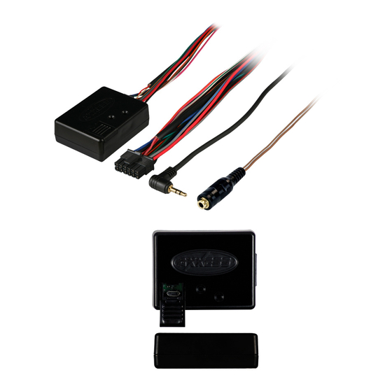
ASWC-1 Connections:
➢ Connect the Black wire of the ASWC-1 and
the wire in Pin 19 of the vehicle's radio
harness shown, to Chassis Ground.
➢ Connect the Red wire of the ASWC-1 to 12v
accessory power.
➢ Connect the Black/Green wire of the
ASWC-1 to the wire in Pin 9 of the vehicle's
radio harness shown.
➢ Connect
the 3.5mm jack to the SWC input on
the back of the radio. If the radio does not have a
3.5mm built in, please refer to Page 2 for wiring
instructions for the Axxess 2 wire adapter.
ASWC-1 Resistive Wire Used:
Black/Green
Programming Method:
Auto-Detect
(No additional actions required)
ASWC-1 VEHICLE SPECIFIC INSTRUCTIONS
Vehicle Connector:
This is the view of the radio connector in the vehicle
Note: Wire colors may vary between vehicles but pin
locations remain the same
Initial Installation:
The first time the ASWC-1 is cycled on, the LED
will begin to "Rapid Flash".
Programming:
When the ASWC-1 begins to flash rapidly, it is in
auto-detect mode, at this time do not press
any buttons. The rapid flash will go out after
several seconds, then simply wait until the LED
goes solid. If it does not go solid, see the "LED
Feedback" section for information on how to
proceed.
**NOTE - If you cycle the ignition on and the ASWC
only shows one Green flash, press and hold the
Reset button for 3 seconds. This will force the ASWC-
1 into Rapid flash/Program mode. If the ASWC-1
goes to a slow Green/Red flash you held the reset
button too long, repeat the 3 second press again.
LED Feedback:
➢ Rapid LED flash Red/Green between 3-
5 seconds
➢ Pause for 1-2 seconds
➢ Series of 7 Green LED flashes. (The
ASWC-1 is detecting wires connected to
the vehicle)
➢ Pause for 1-2 seconds
➢ Series of up to 18 Red LED flashes
(The ASWC-1 is detecting the radio. List
of radios on pg. 2)
After this sequence one of two things will happen.
Either the LED will go solid Red, which means
the ASWC-1 has detected the vehicle, or the
ASWC-1 will go back to a slow Red/Green flash.
This means the ASWC-1 did not detect the
vehicle, and connections should be rechecked, or
programming method should be verified.
Additional LED information:
After the ASWC-1 stops rapid flashing, it will pause
then go directly to 7 Green flashes. Short flashes
indicate wires that are not connected, Long flashes
indicate wires that are connected. *NOTE – The
ASWC always flashes Green 7 times, this is an
indicator of the ASWC-1 wires. After the green
Advertisement

Subscribe to Our Youtube Channel
Related Manuals for Axess ASWC-1

Summary of Contents for Axess ASWC-1
- Page 1 Reset button for 3 seconds. This will force the ASWC- 1 into Rapid flash/Program mode. If the ASWC-1 goes to a slow Green/Red flash you held the reset ➢ Connect the Red wire of the ASWC-1 to 12v button too long, repeat the 3 second press again. accessory power.
-
Page 2: Operation
Menus sometimes need to be set to the vehicle, much like programming on an ASWC-1 you can determine if you the ASWC-1 was set to the vehicle. If after going through are having a vehicle or a radio issue. If the LED on the... - Page 3 Solid Brown wire on the ASWC-1 3.5mm adapter. ASWC-1 Button Remapping ASWC-1 button remapping will be used for people that want to change button function from one thing to another, once the ASWC-1 has been auto detected in a vehicle.
-
Page 4: Troubleshooting
*Note: All Remapping and Dual Press features can be procedure will abort, and the LED will go off. this is done, reset and reprogram the ASWC-1 (as done through the Axxess PC & Android app (Phones must seen in the beginning of the instructions). - Page 5 Harness Wire Locations:...
Need help?
Do you have a question about the ASWC-1 and is the answer not in the manual?
Questions and answers