Advertisement
- 1 Introduction
- 2 Safety Precautions
- 3 Connections
- 4 Technical data
- 5 Flying system used
- 6 Assembly and flying the loudspeakers
- 7 Adjusting the angle between loudspeakers
- 8 Stand mounted system
- 9 Configuration
- 10 Placement
- 11 Safety
- 12 Mounting speakers in columns
- 13 Flying system
- 14 Cabling
- 15 Documents / Resources
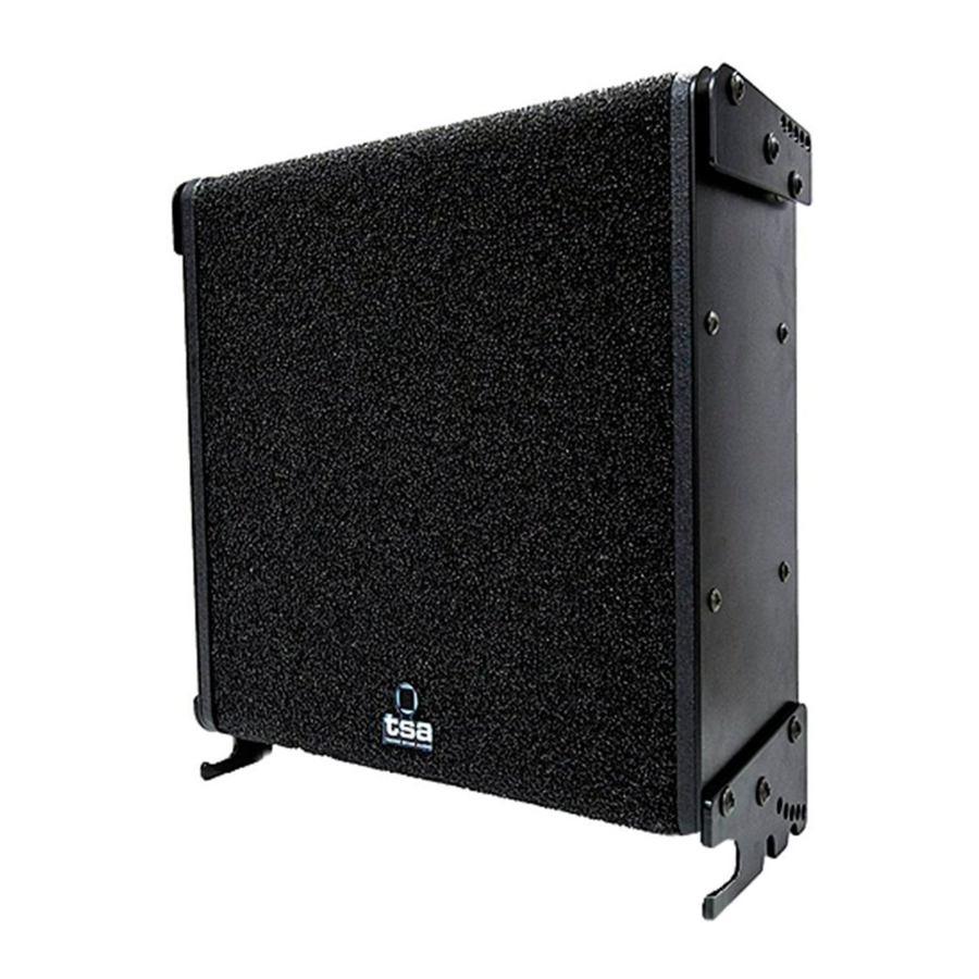
Introduction
Z-600 is the most market plane line array system. With variable directivity, the height of each unit is 20 inch. The 2 -way speaker cabinet is powered by one single amplifier channel (HF crossover network) and mounts two 10-inch low-mid frequency for a deep response and 6x1-inch high frequency piezoelectric horns that offers a brilliant and crispy high frequencies.
This cabinet offers a wide range of possibilities for permanent and mobile installations and is an excellent choice for medium and small sound reinforcement applications. Low frequencies can be reinforced with the SB-15 or SB-18LX subwoofer.
The mechanical design (HZ-600) of the Z-600 enables vertical angles between units of 0 to 10 degrees without use of flying pins allowing easy and quickly deployment for just one operator. The rigging frame (CHSEZ600) uses the same rigging system as the cabinets.
Safety Precautions
 The exclamation point inside an equilateral triangle indicates the existence of internal components whose substitution may affect safety. The specifications can be found on the rear label of the product.

This symbol on the product indicates that this product should not be treated as household waste.

Instead it shall be handed over to the applicable collection point for the recycling of electrical and electronic equipment. The double square indicates Class II device. Do not expose to rain or moisture.

Do not place loudspeakers in proximity to devices sensitive to magnetic fields such as television monitors or data storage magnetic material.
Connections

The units comprise two Neutrik Speakon model NL4 connectors, designed specifically for loudspeakers, are used to ensure both professional and safe connection. To plug a cable into a unit, insert the male plug into any of the enclosure's sockets and turn the male plug to the right so that it is locked. The two connectors are in parallel (all pins) so that either one of them can be used for input or output.
Technical data | Z-600 |
| Usable bandwidth (-10dB) | 80 - 20.000Hz |
| Maximum SPL (*) | 136 dB (preset) |
| Coverage angle (-6 dB). Horizontal: | 90° |
| Vertical Coverage: | Depends of the array elements and curvature |
| Transducers LF: | 2 x 10'' LF woofer |
| Transducers HF: | 6 x 1'' HF unit |
| Nominal impedance: | 4/16 Ω |
| AES power handling: | 600 W |
| Connectors: | 2 x NL4 |
| Rigging components: | 4-point rigging system |
| Permissible flight load: | 12 units |
| Inter-enclosure angles (degrees): | 0 / 0.25 / 2.5 / 5 / 10 |
| Physical data | |
| W x H x D: | 560 x 540 x 150 mm. |
| Weight (net): | 19 kg. |
| Cabinet: | First grade Baltic birch plywood |
| Side panels: | Steel rigging hardware |
| Finish: | High resistance rough black paint |
| Front Steel grill: | Steel grid with anti-corrosion coating and foam |
| Rigging components: | High grade steel with anti-corrosion coating |
(*) Peak level at 1 m under free field conditions using 10 dB crest factor pink noise with specified preset.
Connections

Dimensions

Flying system used
The cluster can easily be rigged by a single operator: The system uses a variable setting between 0° and 10° to determine the angle between units. The flying system hardware has the same regulating mechanism as the rest of the units.
Rigging instructions:
- Place the loudspeaker on the floor in the upright position (See Figure 1).
![]()
- Hold the flying system hardware in your right hand ready to insert it into the top of the loudspeaker. (See Figure 2).
![]()
- The flying system hardware is inserted into the top groove of the loudspeaker by tilting down the back end of the hardware 10 degrees and sliding the piece forward until it stops (See Figure 3).
![]()
- Push the back end of the flying system hardware down until it aligns with the holes. In this way we set the angle we want. Finally, with the left hand, insert the pin into the proper hole, (See Figure 4).
![]()
- Once the two flying system hardware pieces are installed, we repeat the same operation for each of the units that make up the array system (See figure 5).


Assembly and flying the loudspeakers
- Once the flying system hardware has been fitted to the first loudspeaker, slot the topside of the second loudspeaker into the protruding piece on the bottom of the first loudspeaker.
![]()
- Tilt the bottom of the second loudspeaker 10 degrees and slide inwards until it stops.
![]()
- As you slowly release the loudspeaker, with its own weight it will swing to the 0° position where a safety mechanism will lock it in place. You can now safely let go of the loudspeaker.

- With the left hand swing the loudspeaker to set the angle you want. Finally with the right hand, insert the pin, (See Figure 4).


Adjusting the angle between loudspeakers
These speakers incorporate mechanisms to calibrate the vertical angle of inclination between units (ranging from 0 to 10 degrees). Depending on where we insert the pin we can obtain the following angles between units: 0° / 1.25° / 2.5° / 5º / and 10º, (See Figure 2).
Stand mounted system
The cluster can be mounted upside down, using the flying system hardware as a support (See Figure 1). A maximum of two loudspeakers can only be used with this type of assembly.
Configuration

Placement
If you are using microphones, place the loudspeakers in front of them. Feedback occurs when the microphones pick up the sound coming from the loudspeakers and send it through the system again. Feedback can seriously damage your unit. If you only have limited space, point the loudspeakers to an area where there are no microphones to reduce feedback. If you use turntables, place the loudspeakers far away from the turntables. If the turntable's needle picks up the signal from the loudspeakers, it re-amplifies it and low frequency feedback occurs. We recommend that the turntable has a solid base.
Safety
It is important that the loudspeakers are used safely. These models of loudspeakers are capable of producing extremely high sound levels and should be used with caution.
Hearing loss is cumulative and it can affect people who are exposed to sound levels higher than 90dB for long periods of time. Never remain in the vicinity of loudspeakers that are emitting high levels of sound.
Mounting speakers in columns
Make sure that the floor or stage is strong and has a level surface.
Do not stack up too many speakers in outdoor applications where the wind could move them. Please note that loudspeakers operating at very high sound levels can move or vibrate and shift from their original position.
Flying system
Z series speakers are equipped with flying system hardware as indicated of this manual. Using this system a maximum of 12 units can be flown, one 50 mm below another, using the anchor pins as shown in this drawing. As can be seen, the top flying system hardware is designed to: Fly the suspended group of units with slings or supported by a 50 mm diameter tube, as shown in the drawing.

Cabling
When connecting a loudspeaker system to an amplifier it is recommended that the return resistance of the cable used is less than one tenth of the nominal impedance of the system or systems connected in parallel. If the connection cables have a small crosssection, or are too long, the system impedance will be increased and therefore a voltage drop will be produced, thus reducing the power reaching the
Documents / ResourcesDownload manual
Here you can download full pdf version of manual, it may contain additional safety instructions, warranty information, FCC rules, etc.
Advertisement


Need help?
Do you have a question about the Z Series and is the answer not in the manual?
Questions and answers