
Related Manuals for NEC LED-06AF1


Summary of Contents for NEC LED-06AF1
- Page 1 NEC Display Solutions, Ltd. User Manual Control Software for LED Video Wall LED Wall Manager (English Version. 0.2) 2010.09.28(Rev. 0.2)
-
Page 2: Table Of Contents
NEC Display Solutions, Ltd. Content 1. Preparation 2. Software Installation 3. Connection of Equipment 4. Setup LED Wall 5. Light Sensor 6. Control Video Processor 7. Trouble Shooting Windows is a registered trademark of Microsoft Corporation. HDMI is a trademark or registered trademark of HDMI Licensing LLC. -
Page 3: Preparation
NEC Display Solutions, Ltd. This software can set up LED Video Wall, control LED modules and get status of LED Video Wall. 1. Preparation 1.1 OS Windows XP Home Edition / Professional SP3 Windows Vista... Windows 7... 1.2 Specification of computer... -
Page 4: Software Installation
NEC Display Solutions, Ltd. 2. Software installation 2.1 Installation of the device driver of USB/RS-485 adaptor Note: Connect USB/RS-485 adaptor to your computer after this installation process. Set the CD-ROM in your computer. SETUP.exe(Name is T.B.D.) (from ¥Driver¥SETUP.exe , the folder is T.B.D.) Click Confirm the content and if you can agree it, select ”... - Page 5 NEC Display Solutions, Ltd. Click After confirmation that “Launch the CP210x VCP Driver Installer.” is checked, click Click The following dialog box informs that the installation of the device driver is completed. Click and set USB/RS-485 adaptor in your computer.
- Page 6 NEC Display Solutions, Ltd. 2.2 Installation of LED Wall Manager. Before installation of LED Wall Manager, confirm Microsoft .NET Frameworks 3.5 SP1 or later version is installed in your computer. Set the CD-ROM in your computer. SETUP.exe(Name is T.B.D.) (from ¥Software¥LED Wall Manager¥SETUP.exe , the folder is T.B.D.) Click 2010.09.28(Rev.
- Page 7 NEC Display Solutions, Ltd. Click Check “Complete” and Click Click 2010.09.28(Rev. 0.2)
- Page 8 NEC Display Solutions, Ltd. (On Installing) Click , then installation is finished. [Notes] The current problems of Application installation (1) When installation is finished, the short-cut of Screen Service is registered in Stat-up. After re-starts PC, Screen Service program runs and it cause that Configuration.exe cannot run. It is necessary to close Screen Service which is resided in TASK TRAY.
- Page 9 NEC Display Solutions, Ltd. 3. Connections of the equipment 3.1 Connections of Computer, USB/RS-485 adaptor and Video Distributor (LED-VD1) (1) Set USB/RS-485 adaptor to your computer. (2) Connect USB/RS-485 adaptor with Port1 (RJ-45) of Video Distributor with LAN cable (Straight type).
-
Page 10: Setup Led Wall
NEC Display Solutions, Ltd. 4. Set up LED wall To run the software; From Windows OS, START Programs NEC Display Solutions Configuration Window Explanation Icons Icon Function Installation and Control of LED Wall. Control Video Processor. Registration of equipment (Video Distributor, Light Sensor) Communication setting for RS-485. - Page 11 NEC Display Solutions, Ltd. 4.1 Communication Settings (RS-485) (1) Confirmation of COM Port Set USB/RS-485 adaptor to your computer. [Windows XP] START Control Panel System Hardware Device Manager Confirm Ports (COM & LPT). [Windows Vista/Windows 7] Control Panel Hardware and Sound Device Manager Confirm Ports (COM &...
- Page 12 NEC Display Solutions, Ltd. (2) Communication Settings To click have Communication window opened. To click pull-down list of COM Port shows the COM port which can be used. Select the COM Port which you confirmed by (1). The other settings shall be used with default settings.
- Page 13 NEC Display Solutions, Ltd. 4.2 Registration of Equipments Click , then Option window will be opened. To click “New” shows the equipment list by pull-down menu. Click “Distributor”, and then “Add VideoDistributor” window will be open. Input the number from 1 to 40 at Device ID and input the number which is shown at Video Distributor.
- Page 14 NEC Display Solutions, Ltd. (Caution)If Tag Name is wrong, following window will be displayed. The digit is wrong. The wrong number is input. If you need the registration of some equipments, repeat the process of “New ~ Add VideoDistributor”. Device ID should be different number.
- Page 15 NEC Display Solutions, Ltd. 4.3 LED Module Detection Click , then three icons are displayed. This process shows how many LED modules are connected for each output of Video Distributor. , and “Module Table” window is opened. Click Check ports which are used and click To check “All”...
- Page 16 NEC Display Solutions, Ltd. , then “Module Table” will be closed. Confirm the searching is correct and click Mapping of LED modules , then “Screen Wizard” window is opened. Click Click of Advance Setting, open the advanced settings 2010.09.28(Rev. 0.2)
- Page 17 No checked will set Gamma is “2.2”. Checked will show the pull-down menu. Select the gamma correction (1.8, 2.0, 2.2, 2.4). Signal Shift Signal timing offset. Do not change the default value. *1: LED-06AF1: set “80”, LED-15BF1: set “32”. 2010.09.28(Rev. 0.2)
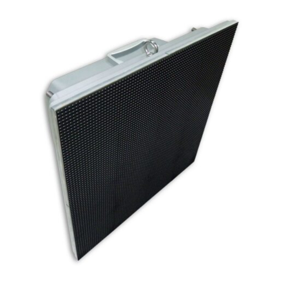
- Page 18 Module-8 Module-10 Module-11 Module-12 Module-9 EXAMPLE: 4 x 3 LED Wall with LED-06AF1. Set 4 at “Horizontal(Frame)”, Set 3 at “Vertical(Frame)”, Set 80 at “Width(Pixel)” and set 80 at “Height(Pixel)”. Click , and go to the next step. 2010.09.28(Rev. 0.2)
- Page 19 NEC Display Solutions, Ltd. Click Click The color of Screen matrix will be changed to cyan, then click The mapping will start. 2010.09.28(Rev. 0.2)
- Page 20 NEC Display Solutions, Ltd. If the following window is displayed, the mapping is completed. (Module mapping) , then “Screen Wizard” window will be closed. Click The LED wall image is displayed as a follow. 2010.09.28(Rev. 0.2)
- Page 21 NEC Display Solutions, Ltd. (2) Manual Settings Typical connection: cascade connections for the horizontal line by each DVI-out of Video Distributor. Module-1 Module-2 Module-3 Module-4 Detection of LED modules 4 modules are connected with Port1 of Video Distributor. Select Port 1 and click Confirm that 4 LED modules are detected.
- Page 22 NEC Display Solutions, Ltd. Set Modules and Module resolution as follows. Mapping two LED modules for Port1 connection of Video Distributor Click “Port1 (2)” of Image Output. Two modules are displayed in Physical Module box. Click in Physical Module box, then Module-1 is selected.
- Page 23 NEC Display Solutions, Ltd. Click (1, 1) in Screen matrix, and then it will be selected. Click , Module-1 will be registered at (1, 1) in Screen matrix. Similarly, Module-2 is registered in (1, 2). Click in Physical Module, and then click (1, 2) in Screen matrix.
- Page 24 NEC Display Solutions, Ltd. Click in Physical Module, and then it will be selected. Click (2, 1) in Screen matrix, then it will be selected. Click , and then Module-3 will be registered at (2, 1) in Screen matrix. Click in Physical Module.
- Page 25 NEC Display Solutions, Ltd. Click , then Module-4 will be registered at (2, 2) in Screen matrix. Click , then Mapping Settings will start. , then “Screen Wizard” window will be closed. Click 2010.09.28(Rev. 0.2)
- Page 26 NEC Display Solutions, Ltd. The LED wall image is displayed as a follow. 2010.09.28(Rev. 0.2)
- Page 27 NEC Display Solutions, Ltd. Z shaped connection Module-1 Module-2 Module-3 Module-4 Detection of LED modules 4 modules are connected with Port1 of Video Distributor. Select Port 1 and click Confirm that 4 LED modules are detected. , then “Module Table” will be closed.
- Page 28 NEC Display Solutions, Ltd. , then “Screen Wizard” will display the next setting window. Click Registration of 4 modules in Physical Module to Screen matrix. 2010.09.28(Rev. 0.2)
- Page 29 NEC Display Solutions, Ltd. Click , then 4 LED modules are displayed in Physical Module. Registration of Module-1 Click in Physical Module. Click (1, 1) in Screen matrix, then it will be selected. Click , then LED module-1 will be registered in Screen matrix.
- Page 30 NEC Display Solutions, Ltd. Register in Physical Module to Screen matrix. Click , then Mapping settings will start. , then “Screen Wizard” window will be closed. Click 2010.09.28(Rev. 0.2)
- Page 31 NEC Display Solutions, Ltd. S shaped connection. Module-1 Module-2 Module-4 Module-3 Module-5 Module-6 Detection of LED Modules 6 modules are connected with Port1 of Video Distributor. Check Port 1 of Module Table and click , then modules detection will start.
- Page 32 NEC Display Solutions, Ltd. Set Modules and Module resolution as a follow. , then “Screen Wizard” will be changed as a follow. Click Registration of 6 modules in Physical Module to Screen matrix. 2010.09.28(Rev. 0.2)
- Page 33 NEC Display Solutions, Ltd. Click , then 6 LED modules are displayed in Physical Module. Registration of Module-1 Click in Physical Module. Click (1, 1) in Screen matrix, then it will be selected. 2010.09.28(Rev. 0.2)
- Page 34 NEC Display Solutions, Ltd. Click , then LED module-1 will be registered. Registration of Module-2. Click and select (1, 2) in Screen matrix. Click , then LED module-2 will be registered. Registration of Module-3. Click and select (2, 2) in Screen matrix.
- Page 35 NEC Display Solutions, Ltd. Needs to change the direction because of the left connection for module-3 and module-4. Click and select Left. The icon will be changed. Click , and then Module-3 will be registered. Registration of Module-.4 Click and select (2, 1) in Screen matrix.
- Page 36 NEC Display Solutions, Ltd. Registration of Module-5 Click and select (3, 1) in Screen matrix. Needs to change the direction because of the right connection for module-5 and module-6. Click and select Right. The icon will be changed. Click , then Module-5 will be registered.
- Page 37 NEC Display Solutions, Ltd. Click , then LED module-6 will be registered. Click , then Mapping settings will start. To click makes Mapping finished. 2010.09.28(Rev. 0.2)
- Page 38 NEC Display Solutions, Ltd. The LED wall image is displayed as a follow. 2010.09.28(Rev. 0.2)
- Page 39 NEC Display Solutions, Ltd. 4.3 Screen Control (1) Select LED modules LED Modules which you select can be controlled. Put the mouse cursor on the module, and left-click with the mouse. The selected module will be changed from Cyan to Blue.
- Page 40 NEC Display Solutions, Ltd. (2) Gamma To set Gamma correction Click pull-down menu shows the list. Select the value and click (3) Dimming To set Dimming level (Brightness setting) of selected LED modules. To click the pull-down menu show the list of Dimming from 0 to 64.
- Page 41 NEC Display Solutions, Ltd. (4) Color Correction [T.B.D.: Under confirmation] To select one LED module shows Color Correction tag. (5) Color Temperature [T.B.D.: Under confirmation] To select two or more LED modules shows Color Temperature tag. 2010.09.28(Rev. 0.2)
-
Page 42: Light Sensor
NEC Display Solutions, Ltd. 5. Light Sensor [T.B.D.] 5.1 Registration of Light Sensor T.B.D. 5.2 Setting , then “Light Sensor Setting” window is opened. Click (1) Check “Auto Dimming”. (2) Select “Dimming Timer”. (3) Click Load Dimming Table to open Dimming Table file. -
Page 43: Control Video Processor
NEC Display Solutions, Ltd. 6. Control Video Processor Connect serial port between Video Processor and your computer. Turn AC power of Video Processor on. Run Configuration.exe. Click Click in order to register Video Processor if using Video Processor function at the first time or a new connection. - Page 44 NEC Display Solutions, Ltd. 6.1 Communication Setting To click pull-down menu of “COM Port” shows the COM Ports which you can use. Select the COM port which is connected with Video Processor. To click shows the Communication setting window. No need to change the default settings.
- Page 45 NEC Display Solutions, Ltd. 2010.09.28(Rev. 0.2)
- Page 46 NEC Display Solutions, Ltd. 6.2 Content and Control 6.2.1 Main Power Indicates POWER OFF. (The power mark is amber.) To click the button will turn power on. Indicates POWER ON. (The power mark is green.) To click the button will turn power off.
- Page 47 NEC Display Solutions, Ltd. 6.2.3 Layout The size and position of content can be adjusted as Fig5.1. After setting, click Width (0,0) Height (1023,767) Fig5.1 6.2.4 Picture Select the function from the pull-down menu (Brightness / Contrast / Color / Tint / Sharpness).
- Page 48 NEC Display Solutions, Ltd. 6.2.5 Input Position [T.B.D.] 6.2.6 Information of Video Distributor To click Update button informs Status of Video Processor. 2010.09.28(Rev. 0.2)
-
Page 49: Trouble Shooting
NEC Display Solutions, Ltd. 6. Trouble shooting Phenomenon Cause and Countermeasure Cannot install L Wall Manager. This software requires Microsoft .NET Frameworks 3.5. SP1. (1) If a following dialog box is displayed, “Microsoft .NET Frameworks 3.5. SP1” Software cannot run.
Need help?
Do you have a question about the LED-06AF1 and is the answer not in the manual?
Questions and answers