Progress Equal-i-zer 90-00-0600 Manual
- Owner's manual (32 pages)
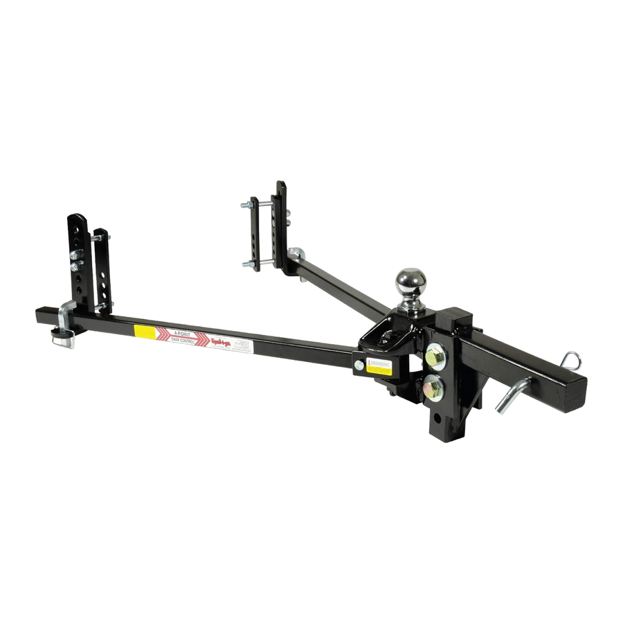
Advertisement
- 1 TOOLS NEEDED FOR INSTALLATION
- 2 Setup Location
- 3 Install the Hitch Ball
- 4 Attach Hitch Head to Shank
- 5 Sway Bracket Assembly Set Up
- 6 Tension Spring Arms
- 7 Weight Distribution Adjustments
- 8 Trailer Angle Adjustment
- 9 Final Tightening
- 10 Regular Maintenance
- 11 Troubleshooting Guide
- 12 Weight distribution Adjustments
- 13 Important Safety Information
- 14 Important Hitch Information
- 15 Documents / Resources
TOOLS NEEDED FOR INSTALLATION
The following tools will allow you to install the hitch properly.
1 1/8" Box End Wrench (Shank Bolts)
3/4" Box End Wrench (link plates and l-brackets)
1 1/8" Socket (Shank Bolts)
3/4" Socket Wrench (link plates and l-brackets) 5/8" Socket or Box End Wrench (angle Set Bolt) measuring Tape pencil
Torque Wrench capable of 320 ft. lbs. of torque. (Shank bolts)
Recommended tools for installing the Hitch Ball:
1 7/8" Thin walled socket (available from progress mfg. Inc.) Torque Wrench capable of 430 ft. lbs. of torque (or higher if hitch ball manufacturer specifies).


Setup Location
Before installing the hitch, the tow vehicle and trailer should be loaded just as they will be while traveling. This includes full propane and fresh water tanks, and any other cargo the tow vehicle (passengers & gear) or trailer will carry, including aTVs for toy haulers. Tow vehicle "auto-level" systems should also be disabled or turned off.
Park the trailer and tow vehicle on level ground and in line with each other. chock and uncouple the trailer. pull tow vehicle ahead about 5 feet to allow working area and set the parking brake.
Take the initial setup measurements for the tow vehicle by measuring from the ground to the top of the wheel wells directly above both the front and back axles of the tow vehicle. See figure 13. Record these on line a of the Weight Distribution adjustments table in Step 6. measure the FRONT and BacK of the trailer frame, and adjust the trailer to be parallel to the ground. Both fRONT and BacK measurements should be the same.
Install the Hitch Ball

Never exceed the specified weight ratings for the trailer, tow vehicle, hitch, hitch ball, or any other towing equipment.
NOTICE
Using a hitch ball with a shank longer than 2‑3/8" may damage hitch and could void your warranty.
Remove the hitch head from the packaging and install a properly-sized hitch ball (not included). Ball diameter must match trailer coupler size.
Select a ball with a 1-1/4" diameter threaded shank no longer than 2 3/8". If your hitch ball has a smaller shank you must use an appropriate bushing. make sure that the ball has a weight rating equal to or greater than your trailer's gross vehicle weight rating (GVWR). always use a lock washer against the nut, unless otherwise specified by ball manufacturer. Torque nut to ball manufacturer's specifications.
Official Equal-i-zer® hitch balls are manufactured for the right fit and may be purchased from your local RV dealership or online at www.equalizerhitch.com. If another brand of hitch ball is used, make sure that it meets size requirements and meets or exceeds all weight ratings.
Hitch balls require a 1-7/8" socket and a torque wrench capable of approximately 450 ft. lbs. torque for installation. Your nearest Equal-i-zer dealership will have the tools needed and will usually install the hitch ball for a reasonable fee.
Attach Hitch Head to Shank
With the trailer parallel to the ground, measure from the ground to the top of the trailer coupler. See Figure 1.

Trailer coupler Height:
The hitch ball should initially be placed as close to this height as possible. Insert the adjustable shank into the receiver on the tow vehicle and secure it with hitch pin and clip.
Insert the spacer rivet with washers into the back of the hitch head to pre-load the angle of the hitch head. Start with 5 spacer washers for longer wheelbase tow vehicles like pickup trucks, and 4 spacer washers with shorter wheelbase vehicles like an SuV. Slide the bolt channel around the shank and hold the hitch head so that the top of the hitch ball measures from the ground as closely as possible to the coupler height. This is generally a step that requires two people.
Observe where the top slot in the bolt channel aligns with the holes in the shank. See Figures 2a - 2b. If you can see any part of the shank hole that is lower than the bolt channel slot, drop the head down to align these holes for the initial setup. See Figure 2a. If you cannot see the lower hole in the shank, raise the hitch head so that the top slot aligns with the shank hole slightly above it, and use this hole for the initial setup. See Figure 2b.


In some cases, the shank may need to be turned upward, or a specialty length shank may be needed so that the ball can be placed at the correct height. See Figure 3.

Insert a 3/4" shank bolt with a flat washer through the top slot in the bolt channel and shank hole to hold the head at the correct height. Slide the flat washer, split (lock) washer, then nut onto the other side of the bolt, and hand tighten them. Then repeat this process for the bottom shank bolt. See Figure 4.

Use a wrench to tighten the angle set bolt until it comes into contact with the shank and lifts the head to where the spacer rivet also comes into solid contact with the shank. Tighten the angle set bolt an additional 1/2 turn. The hitch head should be angled down slightly. See Figure 5.
NOTE: The shank bolts will be fully tightened at the end of the set up and adjustment process.

NOTE: Extended bumper guards, truck campers, or rear mounted spare tires can limit turning radius and may lead to a collision between tow vehicle and trailer in a tight turn unless a longer shank is used. If you are not able to turn tightly with the standard length shank, consult with your dealer about purchasing a longer specialty shank.
Sway Bracket Assembly Set Up
Measure from the center of the coupler along the outside of the trailer frame, and place a mark at 32" on both sides. This is the center mark for the sway bracket assembly. check around the trailer frame and make sure that there are no gas lines, brake lines, or electrical wiring that could be affected by the installation of the link plates. If so, make sure these are re-routed or avoided and will not be disrupted or damaged by the link plate installation.
In some cases where there is an obstruction at 32" that cannot be avoided, the link plates may be moved forward up to a minimum distance of 29" from the center of the coupler. See Figure 6.

Identify the coupler style that most closely matches your trailer. See Figure 7. If yours resembles style B, an under frame coupler, skip to the section marked Style B.

Style A: If your coupler matches style a, place your link plates so that the single hole is above the frame, and Figure 7 the l-bracket studs are toward the top of the frame. See Figure 7a.

Insert two 1/2" x 1-1/2" bolts through each outside link plate from the back side. The slot in the back should keep the head of the bolt from rotating.
Thread a 1/2" x 3-1/2" bolt through the single hole of the outside and inside link plates from the outside in. The head of the bolt should be against the outside link plate with the bolt pointing inward. put a split washer on the bolt and thread a nut onto the end of bolt a few turns. Slide the link plates over the frame as shown so that the bolts for the l-bracket studs are facing outward.
Thread the second bolt through the link plate holes closest to the trailer frame with the head on the outside. put a split washer on the bolt and thread the nut onto it from the back side. Refer to Figure 7b for bolt placement based on your trailer frame height. pinch the inside and outside link plates tight to the trailer frame so that both lay flat against the frame. Inside link plates are sometimes slightly bowed from the manufacturing process. If this is the case, the center of the bow should be placed toward the trailer frame so that as they are tightened they flatten out against the frame.

Continue holding them in place while you hand tighten both nuts. use wrenches to finish tightening the link plate bolts until they are snug, alternating from top to bottom 1/2 turn at a time. Bolts and nuts should be fairly tight, but do not over tighten them. Link plates must be flat against trailer frame to work correctly. uneven or over tightening may cause link plates to bow and "walk" along frame. See Figure 8.
NOTICE
Do not use impact wrench to tighten link plate or l‑bracket bolts.
Slide the l-brackets onto the link plate studs with the spring arm plate facing away from the trailer. for the initial setup, leave 2 holes showing at the top above the studs and two below. They may need to be adjusted up or down later. Thread on the nylock nuts and tighten them.
Style B: If your coupler matches style B, or is a "V-nose" trailer, See figure 7, install your link plates 'upside-down' by placing your link plates so that the single hole is below the frame, the l-bracket studs are toward the bottom of the frame, and the bottom mounting bolt is lifted up tightly to the bottom of the frame. See Figure 7c.

Insert two 1/2" x 1-1/2" bolts through each outside link plate from the back side. The slot in the back should keep the head of the bolt from rotating.
Thread a 1/2" x 3-1/2" bolt through the single hole of the outside and inside link plates from the outside in. The head of the bolt should be against the outside link plate with the bolt pointing inward. put a split washer on the bolt and thread a nut onto the end of bolt a few turns. Slide the link plates up from underneath the frame as shown so that the l-bracket studs are facing outward. Thread the second bolt through the link plate holes closest to the trailer frame with the head on the outside. put a split washer on the bolt and thread the nut onto it from the back side. Refer to Figure 10 for bolt placement based on your trailer frame height.
Pinch the inside and outside link plates tight to the trailer frame so that both lay flat against the frame. Inside link plates are sometimes slightly bowed from the manufacturing process. If this is the case, the center of the bow should be placed toward the trailer frame so that as they are tightened they flatten out against the frame continue holding them in place while you hand tighten both nuts. Use wrenches to finish tightening the link plate bolts until they are snug, alternating from top to bottom 1/2 turn at a time. Bolts and nuts should be fairly tight, but do not over tighten them. Link plates must be flat against the trailer frame to work correctly. uneven or over tightening may cause link plates to bow and "walk" along frame. See Figure 8.
NOTICE
Do not use impact wrench to tighten link plate or l‑bracket bolts.
Once the inverted brackets are installed correctly – use a 3/8" x 1" self-tapping washerhead bolt to secure each outside link plate against the frame (see figure 7d). This bolt (95-03-5610) may be obtained from progress mfg. Inc.

Locate the hole in the outside link plate that is nearest the center of the trailer frame (bottom of the four holes). using a center punch, make a mark on the frame through the center of this bracket hole. Then, drill an 11/32" hole at this location. You may want to use a smaller drill bit first to make a pilot hole.
After completing the 11/32" hole, install the 3/8" x 1" self-tapping washer-head bolt. Tighten the bolt until it is snug against the bracket. Be careful not to over tighten and break the bolt.
Slide the l-brackets onto the link plate studs with the spring arm plate facing away from the trailer. for the initial setup, leave 2 holes showing at the top above the studs and two below. They may need to be adjusted up or down later. Thread on the nylock nuts and tighten them.
Illustrations are exaggerated for easier visualization.

Tension Spring Arms
Never tow with loose socket bolts. Tighten socket bolts to a minimum of 45 ft. lbs. torque before each towing session.
NOTICE
Do not pound directly on the sockets to move them. Pounding may cause the sockets to crack or break. Use only the lever force of the spring arm to move tight sockets. loosen the socket bolt if required. re‑tighten them once the socket has been moved.
Insert spring arms into the sockets in the hitch head. arms for the 6K, 10K, and 12K models are not side specific and can be installed on either side of the hitch. arms for the 14K hitch are notched off center slightly. The arm should be inserted into the socket with the notch on the inside, and with the label facing out.
Insert the socket pin through the hole in the socket and spring arm, and secure it with the socket pin clip. You may need to use the spring arm as a lever to spread the sockets open. This is to allow the spring arms to be lifted and placed onto the l-bracket.
Back tow vehicle to trailer and lower coupler onto ball. lock the coupler. continue to retract the tongue jack until it raises off the ground about 1". Measure the tow vehicle height again exactly above the rear axle, to the same point you measured to earlier when uncoupled. record this on line B of the Weight distribution Adjustments table in Step 6.
With the tow vehicle still coupled to the trailer, use the tongue jack to lift both vehicles until you can swing the spring arms into place over the lbrackets. See Figure 9.

If you reach the top of the jack before the spring arms will swing into position, you can use the Snap-up lever to lift the spring arms up and onto the l-brackets. use the l-pins and clips to secure the spring arms on the lbrackets. See Figure 10-11.


With the spring arms resting on the l-bracket and the trailer and tow vehicle in line with each other, check to make sure that there is a minimum of 3" from the end of the spring arms to the center of the link plates. See Figure 12 move and re-tighten the link plates if necessary.
Retract the tongue jack until the weight of the trailer settles onto the tow vehicle, and the foot of the jack comes off the ground about 1".

Weight Distribution Adjustments
Use the following guidelines to set up and adjust your Equal-i-zer for weight distribution. Good weight distribution is a critical component of the Equal-i-zer setup. a hitch that is set up poorly for weight distribution will not perform like one that is set up well. Every tow vehicle and trailer combination will react differently to weight distribution. Refer to appendix B "Weight Distribution adjustments" for a more detailed description of factors that influence weight distribution.
Re-measure the tow vehicle heights exactly as done before in Step 1. Record these new measurements on line c of the weight distribution setup table.

Weight distribution is only one of many things that influence sway. The operator is responsible for making necessary adjustments to all contributing factors in order to minimize sway.
Good adjustment:
You have most likely achieved good weight distribution adjustment if your measurements show the following:
- The fRONT of the tow vehicle measures the same as, or slightly higher than its uncoupled height. (The "front" column of line c is the same or slightly higher than line a).
- The REaR of the tow vehicle is slightly lower than its uncoupled height, but noticeably higher than it is when coupled without weight distribution engaged. (The "Rear" column of line c is between lines a and B, but much closer to a. line c is NEVER HIGHER than line a).See Figure 13 and Figure 14 below.


Over or under adjusted weight distribution decreases tow vehicle stability.
Under or Over adjustment:
If the hitch is transferring too little or too much weight you must make adjustments to the hitch setup. for changes during the initial setup we recommend adding or removing spacer washers first to try and keep the spring arms parallel with the trailer frame. In our experience, this can help reduce the amount of noise the hitch makes during slow, tight turns. It also gives you more adjustment options if needed later.
Once the maximum (8) or minimum (4) number of spacer washers has been reached, further adjustments can be made by raising or lowering the lbrackets. minor adjustments later for changes in loading can usually be done by moving only the l-brackets.
NOTE: Tow vehicle wheelbase significantly effects how the tow vehicle reacts to weight distribution adjustments. Shorter tow vehicles move farther up or down than longer ones with the same washer or lbracket change. You may not notice much movement at all in the front end of a long tow vehicle, while a short tow vehicle may raise or drop significantly.
Under adjustment
occurs when there is not enough weight being transferred to the front axles of the tow vehicle. See Figure 15.

If the fRONT of your tow vehicle is still higher than the unloaded height you are most likely still under adjusted. If the fRONT height of your tow vehicle is just barely below the unloaded height, you may be able to improve handling by increasing the amount of weight you are transferring. With an under adjusted setup your hitch is not giving back as much steering control as it could, nor is it providing as much friction as it could to help reduce trailer sway.
To correct under adjustment you must add more weight distribution force to the hitch by adding spacer washers, or raising the l-brackets.
If this is the initial set up, use the tongue jack to unload the spring arms. Remove the spring arms from the hitch head. uncouple the trailer and pull tow vehicle forward. loosen the angle set bolt and add a spacer washer.
Repeat steps 4 and 5 to re-adjust and check weight distribution.
If you have reached the maximum number of spacer washers, or if adjusting temporarily due to a change in vehicle loading, use the tongue jack to unload the spring arms. Raise the l-brackets 1 hole. move the spring arms back over the l-brackets and retract the tongue jack. Re-measure the wheel wells and check for proper weight distribution.
Repeat Steps 5 and 6 until the measurements show that the hitch is distributing weight well.
Over adjustment
Occurs when there is too much weight being transferred to the front axles of the tow vehicle. See Figure 16.

If the tow vehicle raises above the unloaded height at the rear wheel well your Equal-i-zer hitch is over adjusted. Over adjustment is a rare occurrence, but it is a very dangerous situation where loss of control and jack-knifing is possible, especially in wet or slick road conditions. It is more likely to occur when towing with a very short wheelbase vehicle like an SuV.
To correct over adjustment you must take some of the weight distribution force out of the hitch by removing spacer washers, or lowering the l-brackets.
If this is the initial set up, use the tongue jack to unload the spring arms. Remove the spring arms from the hitch head. uncouple the trailer and pull vehicle forward. loosen the angle set bolt and remove a spacer washer. Repeat Steps 5 and 6 to re-adjust and check weight distribution.
If you have reached the minimum number of spacer washers, or if adjusting temporarily due to a change in vehicle loading, use the tongue jack to unload the spring arms. Lower the l-brackets 1 hole. move the spring arms back over the l-brackets and retract the tongue jack. Re-measure the wheel wells and check for proper weight distribution.
Repeat Steps 5 and 6 until the measurements show that the hitch is distributing weight well.
Trailer Angle Adjustment
After achieving a good weight distribution setup you may need to adjust the attitude (angle) of the trailer. Step back and look at the trailer to see if the front appears to be tipped up or down excessively.
Measure the fRONT and REaR of the trailer again at the same points you did when setting the trailer parallel to the ground in Step 1. Record these measurements on the Trailer attitude adjustment chart below. Find the difference between the highest and lowest heights.
| Highest measurement | |
| lowest measurement | -(minus) |
| Difference between highest and lowest |
If the difference between the highest and lowest measurement is 1-1/4" or more, you should try adjusting the hitch ball height. If it is less than 1-1/4" different, complete Step 8 and tow a short distance with this setup to see how it handles before making any adjustments.
If the higher measurement is the front of the trailer, move the hitch head down 1 hole position on the shank. If the lower measurement is the front of the trailer, move the hitch head up 1 hole position on the shank.
Adjustments made to ball height directly affect how weight is distributed. moving it up on the shank slightly reduces the amount of weight distribution you get from a particular setup. moving it down slightly increases the weight distribution.
After making an adjustment to the ball height, return to Step 6 and check the weight distribution measurements again. Re-adjust the weight distribution if necessary until it falls within the instruction guidelines. Re-check the trailer angle again to see what difference has been made. You may need to try several setups before you get one that shows good weight distribution and trailer angle.
Final Tightening
Do not tow your trailer until all bolts and nuts have been checked and properly tightened, and all pins and clips are securely in place.
When you feel that the number of spacer washers and l-bracket position are giving you good weight distribution, and that the trailer is sitting at a good angle, tighten all of the nuts and bolts securely. With the weight distribution engaged, begin with the angle set bolt, and tighten it until it comes back into solid contact with the shank plus 1/4 turn. Then tighten down both 3/4" shank bolts to 320 ft. lbs. torque.
Double check the nuts holding the l-brackets to make sure they are tight, and also the bolts holding the sway bracket assembly to the trailer to make sure they are secure. check that the spring arms are locked into place with the socket pins and clips. check that the l-pins and clips are in place.
You are now ready to take the trailer out for a tow. Remember to connect the safety brake cable, safety chains, and electrical cables. make sure your trailer brake control is correctly adjusted. Retract the jack completely. Tow carefully at first and pay attention to how it feels. Follow the Troubleshooting Guide in appendix a which suggests ways that can help improve your towing experience if needed.
Regular Maintenance
The friction surfaces of the head and sockets should be kept clean and well lubricated with a good quality lubricant. They should be lubricated before each trip. check for damage or abnormal wear at the beginning of each towing day and replace if necessary. use a rag to clean dirt and road grit from all friction surfaces regularly. all nuts and bolts should be checked before each towing day and retightened or replaced if necessary.
Towing with a loose angle set bolt for an extended period of time can cause abnormal stress on the hitch resulting in accident, severe injury, and property damage.
Pay special attention to the angle set bolt. There is a break-in period for each hitch and towing configuration. This period is not the same for every towing configuration. With use, the spacer washers and rivet may compact slightly leaving a small gap between the angle set bolt and the shank. The bolt should be checked carefully every 100 miles for the break-in period and re-tightened as explained in Step 8. You will notice that over time the need to re-tighten the angle set bolt will diminish, but you should still check it regularly before each towing day as part of your hook-up routine.
Store your hitch out of the weather when not in use. Keep it clean and free from rust. from time to time, use a good quality rust inhibiting spray paint to touch up the finish and keep it looking good. Do not paint over the warning stickers. If the warning stickers become worn or unreadable, contact progress mfg. Inc. for free replacement.
Troubleshooting Guide
| Problem | Possible Cause | Suggested Correction |
Trailer Sway | Not enough weight distribution | follow "under adjustment" guidelines to add spacer washers or raise l-bracket. |
| Tongue weight too light | Weigh loaded trailer and tongue weight. Tongue weight should be a minimum of 400lbs., and usually between 10%-15% of Gross Trailer Weight. follow trailer mfg. guidelines for tongue weight. Reposition load in trailer as needed. Remove cargo carriers or 2nd trailer from rear of trailer. | |
| Incorrect Tire pressure | Check and fill tires as needed to mfg. recommendations. | |
| Socket bolts loose | make sure socket bolts are tightened to between 45-65 ft. lbs. torque. | |
| Tow capacity exceeded | make sure your tow vehicle is rated to tow your trailer's tongue weight and Gross Vehicle Weight. If it's not, DO NOT TOW. | |
| Hitch undersized | check to make sure your hitch rating meets of exceeds both your Gross Trailer Weight Rateing and max Tongue Weight. If it does not, DO NOT TOW. purchase an Equal-i-zer hitch with a higher rating. | |
Tow Vehicle Too High in front | Not enough weight distributed | follow "under adjustment" guidelines to add spacer washers or raise l-bracket. |
Front End feels "floaty" | Not enough weight distributed | follow "under adjustment" guidelines to add spacer washers or raise l-bracket. |
| Trailer is Too low or Too High in front (more than 1-1/2" from level) | Improper hitch ball height | follow Step 7 - Trailer angle adjustment section to change ball height. |
| Improper hitch ball height because shank is too short | consult your local Equal-i-zer hitch dealer about using a specialty length shank. | |
Bent or broken lbracket, l-pin, or link plate | link plates installed too far back from hitch ball center | follow Step 4 and set center of link plates between 29"-32" from the center of the coupler. |
"Walking" Sway Bracket assembly | link plates under-tightened | follow Step 4 to tighten link plates correctly. |
| link plates over-tightened and bowed | follow Step 4 to tighten link plates correctly. If link plate is excessively bent it should be replaced. |
Noise:
In some cases the friction on the l-brackets or sockets also generates noise. This most commonly occurs during slow, tight turns where the tow vehicle and trailer are in a twist. This noise is normal and should be expected. It is an indication that there is friction on the l-bracket and sockets. most of the noise will usually subside after a few uses as the hitch breaks in.
Trailer and tow vehicle loading may also influence hitch noise.
Lubricating the socket joint may help reduce this noise, and is part of the required regular maintenance routine. lubricating the l-bracket joint is optional. A better solution is a set of official Equal-i-zer brand Sway Bracket Jackets. They quiet the ride without the mess of using a lubricant.
Customer Service:
for customer service, replacement parts, and accessories we recommend that you visit your local dealership that is familiar with Equal-i-zer® brand products whenever possible. If at any time you need customer service and are unable to reach a dealership, please call our toll free customer support line at 1-800-478-5578, or visit us online at www.equalizerhitch.com.
Weight distribution Adjustments
You should carefully consider the following items and their effects when setting up initially and when adjusting your hitch before each trip:
- Vehicle wheel base: Shorter wheelbase vehicles react farther and faster than longer wheelbase vehicles to weight distribution adjustments.
- Vehicle suspension: Soft suspensions, such as an SuV will react farther and faster to weight distribution adjustments than stiff suspensions like a 3/4 ton pickup. for a smoother ride, some vehicle suspensions are designed to be very soft with the first few pounds of payload, and to then stiffen as the load increases. This means that initially the springs move a long way with very little weight applied, then later move much less, even with a significant change in applied weight.
- Trailer length: longer trailers will try to force distributed weight forward to the tow vehicle before absorbing it into the trailer suspension. Shorter trailers absorb more of the distributed weight into their suspensions.
- Tongue weight: To operate effectively, your tongue weight should be at least 10% of the gross trailer weight. This provides the sway resisting friction force on the l-brackets and head sockets of the hitch that give it the ability to resist movement and thus to resist trailer sway.
- Trailer loading: This is one of the most significant factors that influences trailer sway. most trailers are designed to have a tongue weight of between 10% and 15% of the overall trailer weight. always follow the trailer manufacturer's guidelines for tongue weight. Trailers that are "back-end heavy" can often cause trailer sway. Trailer loading changes tongue weight dramatically, and loading can change dramatically from one trip to the next, or even during the course of a short weekend trip.
For example; full water and propane tanks that are tongue weight when you leave can become full waste tanks that subtract tongue weight for the return trip. Shifting just 40 gallons of water from the front to the back of your trailer can change 330 lbs. of positive tongue weight to 330 lbs. of negative tongue weight. Toy haulers without toys are designed to have very heavy dry (empty) tongue weights so that when they are loaded with toys they become a more balanced load.
Cargo carriers, bike racks, and second trailers attached to the rear bumper of a trailer add weight to the rear of the trailer that automatically subtracts tongue weight. We recommend that you do not add weight of any form to the rear bumper of your trailer. We also recommend that you do not tow a 2nd trailer under any circumstance. - Trailer coupled attitude: attitude refers to the angle that the trailer is tipped to. It is generally accepted that a trailer should be towed sitting parallel to the ground, or with the front (coupler) tipped slightly down. The front tipped too far up or down may be an indication of improper trailer loading, or a need to adjust the ball height or weight distribution settings.
- Vehicle weight ratings: Each trailer and tow vehicle has a maximum Gross Vehicle Weight Rating (GVWR). Never exceed these ratings. The tow vehicle and towing equipment, including receiver, shank, hitch, and hitch ball all have maximum weight ratings for tongue weight and trailer weight. Never exceed any of these ratings.
REPLACEMENT
A replacement copy of this manual may be www.EqualizerHitch.com or by calling 1-800-478-5578.
KEEP THIS MANUAL
Keep this manual in a safe place as a reference for regular adjustment and maintenance.
FURTHER ASSISTANCE
If you do not understand any part of this manual contact a qualified Equal-i-zer® hitch dealer in your area or progress mfg. Inc. customer service at 1-800-478-5578 or by visiting www.EqualizerHitch.com.
Important Safety Information
Failure follow all safety warnings may result in severe injury or death.
Read, understand, and follow all safety warnings, setup, use, and maintenance instructions of your trailer, tow vehicle, and hitching equipment before installing your hitch or towing your trailer.
Never cut, weld, grind, bend, or modify hitch components in any way.
It is the drivers responsibility to adjust equipment and driving habits to match towing conditions. The driver is responsible for their own safety and the safety of passengers.
Never exceed the specified weight ratings for the trailer, tow vehicle, hitch, hitch ball, or any other towing equipment.
No hitch setup guarantees that trailer sway will be altogether avoided.
Always load trailer correctly. Follow trailer and tow vehicle manufacturers recommendations for placement and quantity of cargo.
Always tow with a minimum tongue weight of 10% of gross trailer weight.
Always use a hitch ball with a rating that equals or exceeds the trailer Gross Vehicle Weight rating (GVWr). Always use a hitch ball size that correctly matches your trailer coupler size and make sure it is coupled securely before towing.
Measuring weight distribution setup well does not ensure safe towing. The operator is responsible for making necessary adjustments to the hitch to optimize weight distribution and sway control. each trip is different, and the weight distribution setup and towing performance should be evaluated by the operator and adjusted when necessary.
Never tow with your hitch adjusted incorrectly.
Check all hardware before each trip. do not tow your trailer until all bolts and nuts have been checked for wear and fatigue, are properly tightened, and all pins and clips are securely in place.
Do not tow your trailer on rough roads. do not tow your trailer through profound ditches, dips, or swales. excessive strain on the spring arms and hitch head may cause hitch fatigue or failure.
If your dealer installed your hitch, make sure to verify that it is still adjusted correctly after loading your trailer and tow vehicle for your trip.
Replace worn, faded, or unreadable warning stickers on the spring arms and arm sockets.
Do not transfer hitch to a different tow vehicle or trailer without re‑adjusting the hitch.

Do not loosen or remove any part of the hitch except the l‑pins and lpin clips while the hitch is under load.
Always secure tow vehicle and trailer with parking brake and wheel chocks before setting up or adjusting hitch.
Important Hitch Information
Weight Distribution:
Weight distribution is the ability of a hitch to transfer some of the tongue weight of the trailer ahead to the tow vehicle axles, and backward to the trailer axles. Without weight distribution the tow vehicle "teeter-totters" on the rear axle of the tow vehicle, and unweights the front axle. proper weight distribution transfers weight back to the front steering axle, forcing it back to the ground.
Proper weight distribution also adds performance to the integrated sway
Control feature of your Equal-i-zer® hitch. The Equal-i-zer hitch requires a minimum tongue weight of at least 10% of gross trailer weight. This tongue weight gets distributed, and helps generate the friction needed to reduce trailer sway.
Sway control:
Integrated sway control is a built-in, patent pending feature of your Equal-i-zer hitch. unlike conventional chain style weight distribution hitches, you do not need to purchase, install, store, or hook up any additional hardware to get the benefits of this sway control. Once the spring arms are tensioned, the sway control is in force.
Integrated sway control works through the connection between your spring arms and l-brackets, and between the sockets and hitch head. The force required by the hitch to distribute weight rests on the l-brackets through the spring arms and forces the sockets into a bind at the head. The Equal-i-zer hitch takes advantage of the steel-on-steel friction generated at these points to help reduce trailer sway.
This added friction makes it much more difficult for the trailer to sway side-to-side while its being towed, as is usual when you encounter a gust of wind, or passing semi. When set up well and properly adjusted for your load, the Equal-i-zer can noticeably reduce sway.
Important Setup Information:
These instructions are a guideline to aid in setting up your hitch. Every trailer and tow vehicle combination requires a different setup and adjustment because of factors like trailer weight and length, trailer loading, hitch weight, and tow vehicle suspension and wheelbase. It is not likely that a good setup for one vehicle combination will work well for another. If you change tow vehicle and/or trailer, you should change the hitch setup too.
You must use your own best judgment to determine if changes to the setup are required to ensure a safe and comfortable towing situation. There is no all-inclusive formula for setting up or adjusting a hitch that will accommodate each combination of trailer and tow vehicle possible.
The setup may need to be changed slightly at times to accommodate changes in your towing configuration, perhaps even during the same trip. for example, a trailer that starts with full clean water and propane tanks, may tow differently when that water becomes black and grey water, and the propane tanks are empty. Or, a trailer loaded with gear for a long cross country trip may tow differently than the same trailer loaded for a weekend getaway. The driver must be conscious of these changes, and adjust the hitch accordingly.
A setup achieving adequate weight distribution usually brings the trailer
Back to a position parallel to the ground after coupling it to the tow vehicle and engaging weight distribution. It also brings the fRONT of the tow vehicle back down to just slightly higher than the uncoupled height. The REaR of the tow vehicle sits slightly lower than its uncoupled height, but noticeably higher than its height when coupled without weight distribution engaged.
There is no such thing as a "perfect" setup. The hitch should be set up to get the best results possible, and then adjusted as necessary for the best performance possible. You, as the operator, are responsible for your safety, and the safety of your passengers. always follow all of the safety precautions described in this owner's manual.
Remember, no setup guarantees that sway and other towing hazards will be altogether avoided. However, when set up and adjusted properly, we are confident that you will experience a much safer and more comfortable towing experience than you would if towing without an Equal-i-zer hitch.
Documents / Resources
References
Download manual
Here you can download full pdf version of manual, it may contain additional safety instructions, warranty information, FCC rules, etc.
Advertisement


Need help?
Do you have a question about the Equal-i-zer 90-00-0600 and is the answer not in the manual?
Questions and answers