Advertisement
Introduction
This service manual was written expressly for TORO® and LAWN-BOY® service technicians. The Toro Company has made every effort to make the information in this manual complete and correct.
Basic shop safety knowledge and mechanical/electrical skills are assumed. The Table of Contents lists the systems and the related topics covered in this manual.
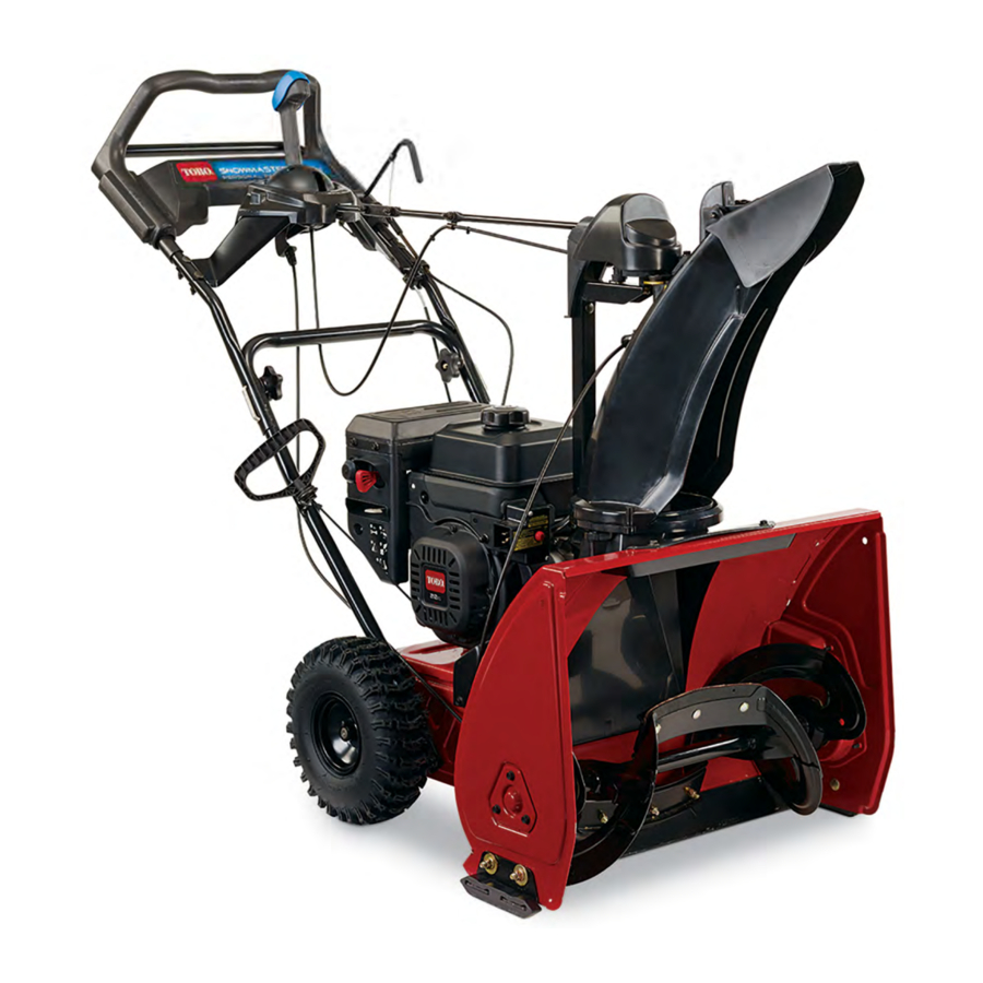
The SnowMaster® and SnowMax® Snowthrower is covered in this manual. The manual may also be specified for use on later model products.
Due to the compact design, parts were removed for photographic purposes when necessary.
We are hopeful that you will find this manual a valuable addition to your service shop. If you have any questions or comments regarding this manual, please contact us at the following address:
The Toro Company Residential Contractor Service Training Department 8111 Lyndale Avenue South Bloomington, MN 55420
The Toro Company reserves the right to change product specifications on this manual without notice.
CHASSIS
Handles and Controls

- Upper Handle
- Lower Handle
- Personal Pace® Handle
- Transmission Cable
- Upper Rotor Cable
- Lower Rotor Cable
 All slack must be removed from the traction cable before cable is secured. Transmission cable to be adjusted so 2.50 ±.05 in. of conduit sticks out past cable anchor. Rear wheels should spin freely in both forward and reverse without Personal Pace® engagement and should lock with Personal Pace® engagement.
 Rotor cable is to be adjusted so 1.00 ±.05 in. of conduit sticks out past cable anchor. Ensure there is slack in cable after adjustment to ensure brake still functions.
Engine

- Engine
- Engine Pulley
Apply a light coat of anti-seize to engine crankshaft, before installing engine pulley.
Apply Loctite® 243 to the threads of the engine mounting studs.
 Pulley groves, item 2, need to be dry and free of oil, anti-seize or other lubricants.
 Torque engine pulley bolt to 170 ± 15 in-lbs. (19.5 ± 1.7 Nm) When inspecting the proper torque, torque must be checked immediately before Loctite® 243 sets up.
Chute Asm.

- Lower Chute
- Chute Guide
- Chute Support Tube Bracket
- Chute Post
- Chute Gear
- Chute
- Chute Handle
- Spring Cover
- Extension Spring
- LH Upper Shroud
- RH Lower Shroud
- Housing Kicker
- Chute Ring
Chute Asm.

- Lower Chute
- Chute Guide
- Chute Post
- Chute Gear
- Chute
- Chute Ring
- Gear Chute Mount
- Face Gear
- Gear Chute Cover
- LH Upper Shroud
- RH Lower Shroud
- Housing Kicker
Chute and Shroud Removal & Replacement (Figure 13 and 14)
Removal
- Remove RH (item 11) and LH (item 10) upper shrouds..
- Remove the bolt and nut attaching the chute post (Figure 13) (item 4). Remove the post and chute assembly.
NOTE: Must remove the quick stick rod and deflector cable clamp on the side of the frame on QS models prior to removing the chute assembly. - Remove the screws that hold the lower chute (item 1) to the housing kicker. (item 12)
- Tip the unit forward. Remove the lower chute (item 1) bottom screws (Figure 15).

- Remove the lower chute (item 1) from the unit.

Replacement
- Install the lower chute (item 1). Install the lower chute bottom screws and the screws that hold the lower chute to the housing kicker (item 12). Torque screws to 25-35 in-lbs. (2.8-4 Nm) (Figure 16).

- Install the chute post (item 3) and chute assembly. Torque to 60 in-lbs. (7 Nm) (Figure 17).
NOTE: Must insert the quick stick rod and deflector cable clamp on the side of the frame on the QS models prior to installing the chute assembly.


- Install the RH (item 11) and LH (item 10) upper shrouds. Torque screws to 25-35 in-lbs. (2.8-4 Nm).
Belt Removal & Replacement
Removal
- Remove the bolts securing the belt cover and remove the cover (Figure 18).

- Unhook the brake spring clip and remove the clip and spring.
- Remove the Rotor Pulley bolt and pull the Rotor Pulley out (Figure 19).

- Work the belt off the jackshaft pulley, remove rotor pulley and belt.


Replacement
- Start the belt over the jackshaft pulley. Route the belt under the idler pulley and between the tabs on the rotor clutch arm. Route the belt over the rotor pulley (Figure 20).

- Slide the rotor pulley onto the rotor shaft. Apply loctite® 243 to the bolt, install the washer and bolt. Torque to 96 in-lbs. (11 Nm) (Figure 21).

- Install the belt cover. Torque bolt to 60-80 in-lbs. (7-9 Nm).
NOTE: Match the orientation of rotor pulley with the above image to prevent putting rotor pulley on backwards.


Rotor and Rotor Drive

- Rotor Center Support
- Paddle
 Torque to 60-80 in-lbs. (7-9 Nm)
 Torque to 40-60 in-lbs. (4-7 Nm)
 Paddles, item B, should be assembled with wear indicator holes in positions shown, when viewed from front.
 Tighten center screw first when assembling rotor paddles. Torque to 45-55 in-lbs.
 Insure rotor assembly, rotates freely after completely installed in frame. Rotor cannot make contact with frame or ground surface.
Rotor Removal & Replacement (Figure 22)
Removal
- Remove the belt cover and remove belt and rotor pulley as outlined in "Belt Removal & Replacement."
- Remove the three bolts from behind the rotor pulley.

- On the opposite side, remove the three bolts on the bearing cap.
- Remove the bearing bolt. Remove the bearing and bearing retainer, rubber washer, and thrust washer.

- Slide the rotor one way and remove.


Replacement
- Make sure the thrust washer, bearing, and bearing retainer are on the rotor shaft on the drive belt side. Insert into the rotor hole. Insert the rotor through the other side of the rotor hole.

- Insert the thrust washer, bearing retainer and bearing. Install the bolt. Torque bolt to 30 ft-lbs. (40 Nm).


- Install the rubber washer and bearing cap. Ensure the rubber washer is properly positioned before installing the bearing cap. Torque bolts to 40-60 inlbs. (4.6-7 Nm).
- Install the bolts that go behind the rotor pulley. Torque to 60-80 in-lbs. (7-9 Nm).
- Install the rotor belt and belt cover as outlined in "Belt Removal & Replacement."
Transmission, Drive and Tire

- Transmission
- Jackshaft Support Plate
- Traction Idler
- Jackshaft Pulley
- Idler Pulley
- Belt
- Jackshaft
- Transmission Bearing Support
 Spring must be assembled into the slot of the traction idler arm and hole in jackshaft support plate.
 Ensure idler arm, pivots freely after assembly.
 Tire and wheel assemblies, should be assembled so the tire tread is going in the correct direction.
Assemble items to jackshaft support plate. Then pass jackshaft assembly through bearing in the left side of the frame then assemble rotor jackshaft pulley to jackshaft. Install transmission bearing support after jackshaft assembly is tightened to left hand side plate. Insure pulley and shaft rotate freely after assembled.
Transmission Cable Removal and Replacement Figure 27)
Removal
- Remove the LH upper shroud. Remove the belt cover.
- Remove the cable end from its retainer (Figure 28).

- Remove the bolt from inside the belt cover (Figure 29).


- Remove the two bolts holding the cable to the chassis (Figure 30).

- Remove cable from the spring.

Replacement
- Place the looped end of the cable on the spring (Figure 31)..

- Install the two bolts holding the cable to the chassis. Torque bolts to 60-80 in-lbs. (7-9 Nm) (Figure 32).


- Insert the bolt through the bolt holes from inside the belt cover into the bracket. Tighten bolts to 60-80 in-lbs. (7-9 Nm) (Figure 33).

- Insert the cable end into its retainer (Figure 34).

- Install the LH upper shroud and belt cover. Torque shroud bolts to 25-35 in-lbs. (2.8-4 Nm). Torque cover bolts to 60-80 in.-lbs. (7-9 Nm).


Transmission Removal
Removal
- Remove the upper shroud. Remove the bolt holding the upper belt cover (Figure 35).

- Tip blower forward resting the auger housing on a protective mat. Remove the fasteners holding the lower belt cover in place. Remove the cover (Figure 36).


- Remove the tensioner spring.
- Remove the wheels from the axles.
- Slide the transmission to the right. Work the belt over the pulley (Figure 37).

- Remove the belt from the crankshaft pulley (Figure 38).

- Slide the belt out.


- Remove the bolts that secure the drive shaft bearings and retainers to the housing (Figure 39).

- Slide the transmission to the right until the left hand axle clears the housing. Lift the transmission up and out. Disconnect the traction cable (Figure 40).


Pulley Removal
Removal
- Remove the transmission from the unit. Remove the two pulley screws.

- Using a punch, tap the pin out of the pulley.


- Slide the pulley back on the shaft.

- Using a puller, pull the bearing off the shaft. Remove the pulley.


Replacement
- Clean the shaft of any debris or rust. Slide the new pulley into the shaft.

- Tap the pulley into position


- Align the pulley holes with the hole in the shaft.

- Insert a pin punch into the pulley.

- Insert the transmission into a vice or clamp to create a solid surface for the pulley to rest on.


- Place bearing on shaft. Using a spacer, tap the bearing in place until the inner race of the bearing is flush with the shaft.

- Remove the pinch punch. Insert the new pin.


- Install screws into the pulley to secure the pin into position.

- Pulley and bearing installation is complete.
![]()


Rotor and Rotor Drive

- Rotor-Pulley Asm.
- Rotor Clutch Asm.
- Flat Idler-Pulley
- Rotor Jack shaft-Pulley
- V Poly-Belt
- Extension Spring
Lubricate idler arm, on both sides around pivot hole with grease.
Spring must be assembled as shown, it must pass through both the slot and hole in spring clip.
Extended pulley hub must be assembled towards the rotor.
Ensure idler arm, pivots freely after assembly.
Jackshaft Removal and Replacement (Figure 54)
Removal
- Remove the belt covers, belt, and transmission from the unit.
- Place a screw driver or similar tool through the hole in the jackshaft (Figure 55).

- Remove the bolt securing the jackshaft/rotor pulley (item 4). Remove the pulley (Figure 56).


- Inside the housing, remove the bolts securing the other jackshaft pulley (item 4). Remove the pulley (Figure 57).

- Remove the three bearing retainer bolts from inside the belt housing (Figure 58).

- Remove the three bearing retainer bolts form the side of the housing. Remove the bearing retainer (Figure 59).


- Loosen the tensioner arm bolt. Move the tensioner out of the way (Figure 60).

- Slide the jackshaft support plate to the right and remove (Figure 61).


Replacement
- Slide the jackshaft, thrust washer, bearing, and bearing retainer into the chassis, through the hole in the belt cover (Figure 62).

- Slide the jackshaft support plate, thrust washer, bearing, and bearing retainer onto the jackshaft inside the housing (Figure 63).


- Install the mounting bolts. Torque to 96 in-lbs. (11 Nm).
- Slide the tensioner arm back into position. Torque to 30 ft-lbs. (40 Nm) (Figure 66).


- Insert a screw drive or similar tool into the hole in the jackshaft. Install the jackshaft/rotor pulley. Apply Loctite® 243 to bolt. Torque to 96 in-lbs. (11 Nm) (Figure 64).

- Install the other jackshaft pulley. Torque to 96 in-lbs. (11 Nm). Install the lower bearing retainer. Torque to 96 in-lbs. (11 Nm) (Figure 65).


Transmission Replacement
Replacement
- Install the traction cable (Figure 67).

- Slide the bearings and bearing retainers on the drive shafts. Insert the left side axle through the hole in the housing and set the right side axle in the axle slot (Figure 68).


- Slide the bearing carriers to the housing and install the mounting bolts. Torque bolt to 96 in-lbs. (11 Nm) (Figure 69).

- Slide the drive belt up through the housing and around the lower pulley (Figure 70).

- Route the belt the correct way and install belt on crankshaft pulley (Figure 71).


- Install the tensioner spring. Check for proper belt routing and tension (Figure 72).

- Install the belt covers and install all mounting bolts.
- Install the wheels. Add anti-seize to lock wheels.
- Replace all shrouds, the drive belt and cover.

Main Frame

- Frame
- Belt Cover
- Scraper Asm.
- Skid Asm.
- Lower Belt Cover
- Upper Belt Cover
- Bottom Ferrule (2x)
- Top Ferrule (2x)
To assemble skids, item D, to correct height with tires and scraper installed and product on lever surface. Place a 0.2 in. thick spacer under scraper. Position the skid so it is resting on the ground, tighten fasteners while holding skid to prevent from rotating.
Bottom ferrule must be assembled such that body extends through frame. Top ferrule must be assembled around bottom ferrule. Neither ferrule can be pinched during assembly.
Torque to 25-35 in-lbs. (2.9-4 Nm)
Torque to 60-80 in. lbs. (7-9 Nm)
Scraper Removal and Replacement (Figure 73)
Removal
- Remove the six bolts that attach the scraper (Figure 73, item 3) to the housing (Figure 74).


Replacement
- Install the new scraper and torque bolts to 96 in-lbs. (11 Nm)
Paddle Removal and Replacement
Removal
- Remove the three bolts that attach the paddle to the rotor (Figure 75).


Replacement
- Insert he new paddle behind the center support. Install the new paddles, tighten the center bolt first. Torque bolts to 45-55 in-lbs. (5.2-6.3 Nm) (Figure 76). Refer to Figure 3.


Quickstick

- Latch Trigger
- LH Chute Lever Cover
- Chute Control Rod
- Lever Cap
- RH Chute Control Lever
- LH Chute Control Lever
- RH Chute Lever Cover
- Chute Rod
Torque to 5-10 in-lbs. (0.5-1.1 Nm)
Clocking the Quick Stick
- Make sure the Quick Stick handle is in the center position.
- Remove the two screws holding the front cover on (Figure 78).

- Loosen the two screws holding the chute gear mount to the Quick Stick chute post (Figure 79).


- Disengage the pawl and pull back on the face gear/ chute gear mount. Rotate the chute until it faces straight ahead. (Figure 80).

- Once clocking is set, tighten the two screws holding the gear chute mount to the quick stick chute mount to 50-60 in-lbs. (5.7-6.9 Nm).
- Using the quick stick, ensure the chute rotates fully to the left and right.
- Install the top cover. Torque bolts to 6-10 in-lbs. (7- 1.1 Nm).

SAFETY INFORMATION
General Information
 This symbol means WARNING or PERSONAL SAFETY INSTRUC- TION - read the instruction because if has to do with your safety. Failure to comply with the instruction may result in personal injury or even death.
This manual is intended as a service and repair manual only. The safety instructions provided herein are for troubleshooting, service, and repair of the Toro SnowMaster ® and SnowMax ® snowthrowers. The SnowMaster operator's manuals contain safety information and operating tips for safe operating practices. Operator's manuals are available through your Toro parts source or:
The Toro Company Publications Department 8111 Lyndale Avenue South Bloomington, MN 55420
Think Safety First
Avoid unexpected starting of engine... Always turn off the engine and disconnect the spark plug wire(s) before cleaning, adjusting, or repair.
Avoid lacerations and amputations... Stay clear of all moving parts whenever the engine is running. Treat all normally moving parts as if they were moving whenever the engine is running or has the potential to start.
Avoid burns... Do not touch the engine, muffler, or other components which may increase in temperature during operation, while the unit is running or shortly after it has been running.
Avoid fires and explosions... Avoid spilling fuel and never smoke while working with any type of fuel or lubricant. Wipe up any spilled fuel or oil immediately. Never remove the fuel cap or add fuel when the engine is running. Always use approved, labeled containers for storing or transporting fuel and lubricants.
Avoid asphyxiation... Never operate an engine in a confined area without proper ventilation.
Avoid injury from batteries... Battery acid is poisonous and can cause burns. Avoid contact with skin, eyes, and clothing. Battery gases can explode. Keep cigarettes, sparks, and flames away from the battery.
Avoid injury due to inferior parts... Use only original equipment parts to ensure that important safety criteria are met.
Avoid injury to bystanders... Always clear the area of bystanders before starting or testing powered equipment.
Avoid injury due to projectiles... Always clear the area of sticks, rocks, or any other debris that could be picked up and thrown by the powered equipment.
Avoid modifications... Never alter or modify any part unless it is a factory approved procedure.
Avoid unsafe operation... Always test the safety interlock system after making adjustments or repairs on the machine. Refer to the Electrical section in this manual for more information.
SPECIFICATIONS AND MAINTENANCE
Torque Specifications
Recommended fastener torque values are listed in the following tables. For critical applications, as determined by Toro, either the recommended torque or a torque that is unique to the application is clearly identified and specified in the service manual.
These torque specifications for the installation and tightening of fasteners shall apply to all fasteners which do not have a specific requirement identified in the service manual. The following factors shall be consid ered when applying torque: cleanliness of the
fastener, use of a thread sealant (e.g. Loctite of lubrication on the fastener, presence of a prevailing torque feature, hardness of the surface underneath of the fastener's head, or similar condition which affects the installation.
As noted in the following tables, torque values should be reduced by 25% for lubricated fasteners to achieve the similar stress as a dry fastener. Torque values may also have to be reduced when the fastener is threaded into aluminum or brass. The specific torque value should be determined based on the aluminum or brass material strength, fastener size, length of thread engagement, etc.
The standard method of verifying torque shall be performed by marking a line on the fastener (head or nut) and mating part, then back off fastener 1/4 of a turn. Measure the torque required to tighten the fastener until the lines match up.
Fastener Identification

Inch Series Bolts and Screws
- Grade 1 & 2
- Grade 5
- Grade 8

Metric Bolts and Screws
- Class 8.8
- Class 10.9
Standard Torque Values (Inch)
")
Standard Torque Values (Metric Fasteners)
| Thread Size | Class 8.8 Bolts | Class 10.9 Bolts | ||
| M5 X 0.8 | 57 ± 5 in-lb | 644 ± 68 N-cm | 78 ± 8 in-lb | 881 ± 90 N-cm |
| M6 X 1.0 | 96 ± 10 in-lb | 1085 ± 113 N-cm | 133 ± 14 in-lb | 1503 ± 158 N-cm |
| M8 X 1.25 | 19 ± 2 ft-lb | 26 ± 3 N-m | 28 ± 3 ft-lb | 38 ± 4 N-m |
| M10 X 1.5 | 38 ± 4 ft-lb | 52 ± 5 N-m | 54 ± 6 ft-lb | 73 ± 8 N-m |
| M12 X 1.75 | 66 ± 7 ft-lb | 90 ± 10 N-m | 93 ± 10 ft-lb | 126 ± 14 N-m |
| M16 X 2.0 | 166 ± 15 ft-lb | 225 ± 23 N-m | 229 ± 23 ft-lb | 310 ± 31 N-m |
| M20 X 2.5 | 325 ± 33 ft-lb | 440 ± 45 N-m | 450 ± 36 ft-lb | 610 ± 62 N-m |
INCH/METRIC NOTE: Reduce torque values listed in the table above by 25% for lubricated fasteners. Lubricated fasteners are defined as threads coated with a lubricant such as oil, graphite, or thread sealant such as Loctite
INCH/METRIC NOTE: Torque values may have to be reduced when installing fasteners into threaded aluminum or brass. The specific torque value should be determined based on the fastener size, the aluminum or base material strength, length of thread engagement, etc.
INCH/METRIC NOTE: The nominal torque values listed above for Grade 5 and 8 fasteners are based on 75% of the minimum proof load specified in SAE J429. The tolerance is approximately ± 10% of the nominal torque value. Thin height nuts include jam nuts.
METRIC NOTE: The nominal torque values listed above are based on 75% of the minimum proof load specified in SAE J1199. The tolerance is approximately ± 10% of the nominal torque value. Thin height nuts include jam nuts.
Other Torque Specifications
SAE Grade 8 Steel Set Screws
Thread Cutting Screws (Zinc Plated Steel)
| Type 1, Type 23, or Type F | |
| Thread Size | Baseline Torque* |
| No. 6 - 32 UNC | 20 ± 5 in-lb |
| No. 8 - 32 UNC | 30 ± 5 in-lb |
| No. 10 - 24 UNC | 38 ± 7 in-lb |
| 1/4 - 20 UNC | 85 ± 15 in-lb |
| 5/16 - 18 UNC | 110 ± 20 in-lb |
| 3/8 - 16 UNC | 200 ± 100 in-lb |
| Thread Size | Recommended Torque | |
| Square Head | Hex Socket | |
| 1/4 - 20 UNC | 140 ± 20 in-lb | 73 ± 12 in-lb |
| 5/16 - 18 UNC | 215 ± 35 in-lb | 145 ± 20 in-lb |
| 3/8 - 16 UNC | 35 ± 10 ft-lb | 18 ± 3 ft-lb |
| 1/2 - 13 UNC | 75 ± 15 ft-lb | 50 ± 10 ft-lb |
Wheel Bolts and Lug Nuts
| Thread Size | Recommended Torque** | |
| 7/16 - 20 UNF Grade 5 | 65 ± 10 ft-lb | 88 ± 14 N-m |
| 1/2 - 20 UNF Grade 5 | 80 ± 10 ft-lb | 108 ± 14 N-m |
| M12 X 1.25 Class 8.8 | 80 ± 10 ft-lb | 108 ± 14 N-m |
| M12 X 1.5Class 8.8 | 80 ± 10 ft-lb | 108 ± 14 N-m |
** For steel wheels and non-lubricated fasteners.
Thread Cutting Screws (Zinc Plated Steel)
| Thread Size | Threads per Inch | Baseline Torque* | |
| Type A | Type B | ||
| No. 6 | 18 | 20 | 20 ± 5 in-lb |
| No. 8 | 15 | 18 | 30 ± 5 in-lb |
| No. 10 | 12 | 16 | 38 ± 7 in-lb |
| No. 12 | 11 | 14 | 85 ± 15 in-lb |
* Hole size, material strength, material thickness and finish must be considered when determining specific torque values. All torque values are based on nonlubricated fasteners.
Conversion Factors
| in-lb x 11.2985 = N-cm | N-cm x - 0.08851 = in-lb 88 ± 14 N-m |
| ft-lb x 1.3558 = N-m | N-cm x 0.73776 = ft-lb 108 ± 14 N-m |
U.S. to Metric Conversions
| To Convert | Into | Multiply By | |
| Linear Measurement | Miles Yards Feet Feet Inches Inches Inches | Kilometers Meters Meters Centimeters Meters Centimeters Millimeters | 1.609 0.9144 0.3048 30.48 0.0254 2.54 25.4 |
| Area | Square Miles Square Feet Square Inches Acre | Square Kilometers Square Meters Square Centimeters Hectare | 2.59 0.0929 6.452 0.4047 |
| Volume | Cubic Yards Cubic Feet Cubic Inches | Cubic Meters Cubic Meters Cubic Centimeters | 0.7646 0.02832 16.39 |
| Weight | Tons (Short) Pounds Ounces | Metric Tons Kilograms Grams | 0.9078 0.4536 28.3495 |
| Pressure | Pounds/Sq. In. | Kilopascal | 6.895 |
| Work | Foot-pounds Foot-pounds Inch-pounds | Newton-Meters Kilogram-Meters Kilogram-Centimeters | 1.356 0.1383 1.152144 |
| Liquid Volume | Quarts Gallons | Liters Liters | 0.9463 3.785 |
| Liquid Flows | Gallons/Minute | Liters/Minute | 3.785 |
| Temperature | Fahrenheit | Celsius |
|
Equivalents & Conversions
Decimal & Millimeter Equivalents

Maintenance
Note: Determine the left and right sides of the machine from the normal operating position.
Recommended Maintenance Schedule(s)
| Maintenance Service Interval | Maintenance Procedure |
| After the first hour |
|
| After the first 2 hours |
|
| Before each use or daily |
|
| Every 100 hours |
|
| Yearly |
|
| Yearly or before storage |
|
Maintenance Safety
Read the following safety precautions before performing any maintenance on the machine:
- Before performing any maintenance, service, or adjustment, stop the engine and remove the key. If major repairs are ever needed, contact an Authorized Service Dealer.
- Check all fasteners at frequent intervals for proper tightness to be sure the machine is in safe working condition.
- Maintain or replace safety and instruction labels, as necessary.
- Do not change the governor settings on the engine.
- Purchase only genuine Toro replacement parts and accessories.
Checking the Engine Oil Level
Service Interval: Before each use or daily
- Remove the dipstick, wipe it clean, then fully insert the dipstick without threading it in.
- Remove the dipstick and check the oil level.
- If the oil level is below the full mark on the dipstick (Figure 1), add oil.
- If the oil level is above the Full mark, drain the excess oil until the oil level is at the Full mark.

- Low oil level—add oil
- Correct oil level
Checking and Adjusting the Skids
Service Interval: Yearly Check the skids to ensure that the auger does not contact the paved surface. Adjust the skids as needed to compensate for wear (Figure 2).

- 5 mm (3/16 inch) board
- Ground
- Loosen the skid bolts.
- Slide a 5 mm (3/16 inch) board underneath the scraper.
Note: Using a thinner board will result in a more aggressive scraper. A thicker board will result in a less aggressive scraper. - Lower the skids to the ground.
Note: Ensure the skids are flat on the ground. - Tighten the skid bolts.
![]()

Inspecting the Throwing Edges
Service Interval: Yearly—Inspect the throwing edges and have an Authorized Service Dealer replace the throwing edges and scraper if necessary.
Before each session, inspect the throwing edges for wear. When a throwing edge has worn down to the wear indicator hole, have an Authorized Service Dealer replace the throwing edges (Figure 3).

- The wear indicator hole is intact; you do not need to replace the throwing edges.
- The wear indicator hole is exposed; replace both throwing edges.
Changing the Engine Oil
Service Interval: After the first 2 hours Yearly
Run the engine a few minutes before changing the oil to warm it. Warm oil flows better and carries more contaminants.
- Move the machine to a level surface.
- Place an oil drain pan under the oil-drain plug, remove the oil-drain plug, and tip the machine backward and drain the used oil in the oil-drain pan (Figure 4).

- Oil-drain plug

- After draining the used oil, return the machine to the operating position.
- Install the oil drain plug and tighten it securely.
- Clean around the oil fill cap.
- Use Figure 5 below to select the best oil viscosity for the outdoor temperature range expected:
Model Max fill 36001, 36002, 38710, 38711 0.5 L (16.9 oz) 36003, 38712 0.7 L (23.7 oz) Oil type: automotive detergent oil with an API service classification of SJ, SL, or higher.
![]()


- Low oil level—add oil
- Correct oil level
Replacing the Spark Plug
Service Interval: Every 100 hours—Replace the spark plug.

Replacing the spark plug while the engine is hot can result in burns.
Wait until the engine is cool to replace the spark plug.
Use a Toro spark plug or equivalent (Champion® RN9YC or NGK BPR6ES).
- Remove the boot (Figure 7).

- Clean around the base of the spark plug.
- Remove and discard the old spark plug. Note: You will need a ratchet wrench extension to remove the spark plug.
- Set the gap between the electrodes on a new spark plug at 0.76 mm (0.030 inch) (Figure 8).
![]()
- 0.76 mm (0.030 inch)


Adjusting the Auger Cable
Service Interval: After the first 2 hours
Yearly
If the drive belt slips or squeals under heavy load, adjust the auger cable.
- Loosen the nut on the lower cable clamp, but do not remove it (Figure 9).

- Nut
- Cable
- Connector
- Spring

- Pull the cable up to remove some slack (Figure 9).
![]()
Do not remove all the slack from the cable. Removing all the slack from the cable will prevent the auger from stopping properly. - Hold the cable in place and tighten the nut (Figure 9).

Adjusting the Transmission Cable
Service Interval: After the first 2 hours
Yearly
If the wheels easily stall out, or if the wheels drive without engaging the self-propel handle, adjust the transmission cable.
- . Loosen the nut on the upper cable clamp, but do not remove it (Figure 10).

- Nut
- Cable

- Pull the cable down to remove most of the slack in the cable (Figure 10).
![]()
Do not remove all the slack from the cable. Removing all the slack from the cable may cause the wheels to engage without engaging the self-propel handle. - Tighten the nut (Figure 10).
Checking the Tire Pressure
Service Interval: Yearly
Set the tire pressure equally in both tires to between 103 and 137 kPa (15 and 20 psi).
Storage
Storing the Snowthrower
- Gasoline fumes are highly flammable, explosive, and dangerous if inhaled. If you store the machine in an area with an open flame, the gasoline fumes may ignite and cause an explosion.
- Do not store the machine in a house (living area), basement, or any other area where ignition sources may be present, such as hot water and space heaters, clothes dryers, furnaces, and other like appliances.
- Do not tip the machine backward with fuel in the fuel tank; otherwise, fuel may leak out of the machine.
- On the last refueling of the season, add fuel stabilizer to fresh fuel as directed by the engine manufacturer.
- Run the engine for 10 minutes to distribute the conditioned fuel through the fuel system.
- Stop the engine, allow it to cool, and siphon the fuel tank or run the engine until it stops.
- Start the engine and run it until it stops.
- Choke or prime the engine, start it a third time, and run the engine until it will not start.
- Drain the fuel in the carburetor through the carburetor drain bolt into an approved gasoline container.
- Dispose of unused fuel properly. Recycle it according to local codes, or use it in your automobile.
- While the engine is still warm, change the engine oil.
- Remove the spark plug.
- Squirt 2 teaspoons of oil into the spark plug hole.
- Install the spark plug by hand and then torque it to 27–30 N-m (20–22 ft-lb).
- With the ignition key in the Off position, pull the recoil starter slowly to distribute the oil on the inside of the cylinder.
- Clean the machine.
- Touch up chipped surfaces with paint available from an Authorized Service Dealer. Sand affected areas before painting, and use a rust preventative to prevent the metal parts from rusting.
- Tighten any loose fasteners. Repair or replace any damaged parts.
- Cover the machine and store it in a clean, dry place out of the reach of children. Allow the engine to cool before storing it in any enclosure.
Documents / ResourcesDownload manual
Here you can download full pdf version of manual, it may contain additional safety instructions, warranty information, FCC rules, etc.
Advertisement


Need help?
Do you have a question about the SnowMaster and is the answer not in the manual?
Questions and answers