Advertisement
INTRODUCTION
To obtain the best performance from the machine and ensure the longest possible life of all its components, you must carefully follow the instructions for use and maintenance detailed in this manual. In the interest of our customers, we suggest any maintenance or repair of the equipment has to be made by qualified personnel.
All our products are subject to constant development. Therefore, we are compelled to reserve the right to make any necessary or useful changes in design and equipment.
ORDINARY MAINTENANCE
 Exposure to extremely dusty, damp, or corrosive air is damaging to the welding machine.
Avoid any deposit of metallic dust inside the generator.
Disconnect the generator from the net before operating any servicing! Standard checks to the generator:
- Operate an internal cleaning by using low pressure compressed air and soft bristle brushes.
- Check the electrical connections and all the rest of the connecting cables. For the maintenance and the use of gas regulators consult the specific handbook.
Please note that: lack of maintenance can spell to the unavailability and cancellation of the guarantee.
POSSIBLE APPLICATION
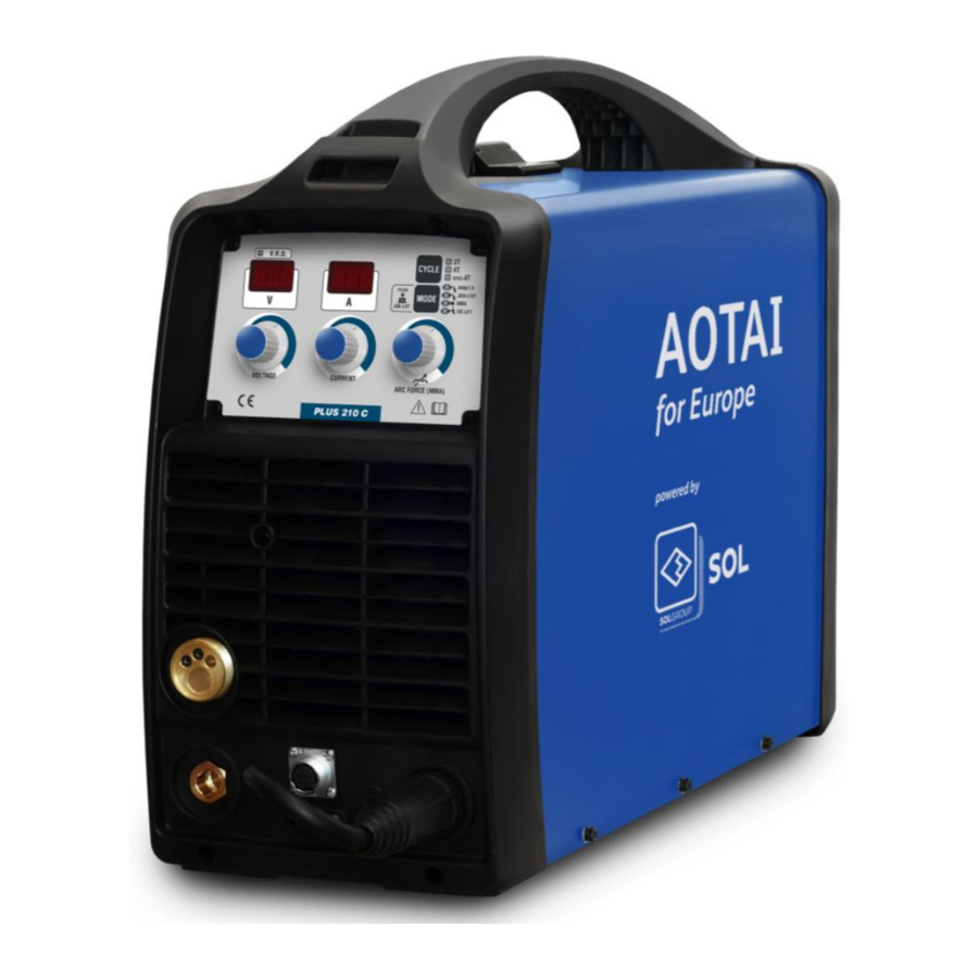
Power sources type PLUS are suited for MIG / MAG applications with pulsation and synergy, FCAW cored wire, MMA and TIG Liftarc with a range up to 210A.
- It is forbidden to use the equipment for different applications from the ones listed in this manual. A different use from the one hereafter described can compromise the security of work and the reliability of the equipment.
We suggest not to use the Inverter Power Source PLUS 210 C (standard version):
- In environments with a high concentration of humidity and dust.
- With Input cables longer than 50 m.
Contact the service centre for advice and precautions, in case the unit must be installed and used under the above-listed conditions.
It is suggested to make a maintenance cleaning of the unit every 2-3 months of work, for this operation, please contact the service centre.
GENERAL PRECAUTIONS
If not opportunely carried out, welding represents a risk for the safety of the operator and of all the people which are within the immediate vicinities. It is recommended, therefore, to observe some fundamental safety rules such as:
- Limit the exposed area to smoke and radiation coming from the welding area by using special welding light screens (ANTIREFLEX) or, if possible, reserve a proper room for these industrial processes.
- Protect the body, in all its parts, with protective clothing and accessories (masks, helmets, etc...) and if possible, clothing needs to be adherent to the operator's body; use shoes with rubber soles in order to be opportunely isolated.
- Limit the fumes and gas formation by using clean, not rusted and not treated metal pieces; contrary, if it is not possible to operate as above, it is recommended the use of masks in order to favour the operator's breathing. Vacuums and ventilation systems should be built in order to grant a continuous air flow.
Positioning of the implant

To correctly position the system, follow these simple rules:
- Ensure easy access to controls and work equipment.
- Do not place the system in a confined space.
- Do not place the system on a surface with an inclination greater than 10° from the horizontal plane.
Warnings on the use of GAS cylinders


Inert gas cylinders contain pressurized gas and may explode if the minimum transport and storage conditions are not ensured.
- Always tighten the valve protection cover during transport, commissioning and whenever welding operations are completed.
- To avoid accidental mechanical drops or shocks, always fix the cylinders vertically to walls or other support with suitable means, chains, belts, etc.
- Do not expose the cylinders directly to sunlight and high-temperature changes. Do not expose the cylinders to too cold or too high temperatures.
- The cylinders must not come into contact with open flames, electric arcs, torches and electrode holders and the incandescent projections produced by welding.
- Keep cylinders away from welding circuits and current circuits in general.
- Keep the head away from the point where the gas leaks when the cylinder valve is opened.
- Always close the cylinder valve when the welding operations are finished.
- Never perform welding on a pressurized gas cylinder.
ELECTRICAL EMERGENCY NORMS
- Avoid working with cables that are in any way deteriorated, and make sure to correctly connect the AC phases and earth on a certified plug.
- Never wrap ground and/or torch cables around the operator's body.
- Avoid operating in humid or wet places without the proper precautions.
- Avoid operating if the machine protective panels (sides and cover) have been removed in order to grant the safety of both the operator and the system.
ANTIFIRE EMERGENCY NORMS
- Equip the workspace with proper fire extinguishers and periodically check the efficiency.
- Position the generator on a solid and horizontal surface making sure of the presence of good aeration. Do not obstruct the front and rear panel; this will let the machine overheat.
- Follow all the regulations applicable when welding has to be carried out on containers of lubricants or flammable substances.
SYMBOLS DESCRIPTION
| | Cautions in operation |  | TIG mode |
 | Items need special instruction |  | Welding current and pre-set current in ampere |
 | It's forbidden to dispose electric waste together with other ordinary waste. Please take care of our environment. |  | Welding voltage and pre-set voltage in volts |
 | MIG/MAG and FCAW mode |  | Electronic inductance |
 | MMA mode |  | Voltage Reduction Device function in MMA |
 | WARNING LABEL The label with the warnings is placed on the machine cover. It must NOT be removed or painted. | ||
COMMANDS DESCRIPTION
General description
Front panel:
|  | |
Rear panel:
|  | |
| Side panel:
|  | |
Front panel description:

Please reference Fig. 4.
| POS. 16 | Display for viewing WELDING CURRENT / JOB-LIST codes. |
| POS. 17 | Button for selecting welding cycle: 2-times (2T), 4-times (4T) and Special 4times (SPEC 4T), see Par. TORCH SWITCH cycle selection. |
| POS. 18 | Button for selecting AlMg1.0, JOB-LIST, MMA, TIG LIFT mode. AlMg1.0 = MIG mode for aluminum Ø 1.0. JOB-LIST = Synergic and/or pulsed MIG mode for expert welders for welding aluminum, carbon steel, stainless steel and cored wire. Select the JOB-LIST codes based on the material to be welded, the type of gas, the chosen wire diameter and with or without pulsation. Refer to Par. MIG/MAG setting and the table shown inside the spool holder compartment of the machine.
MMA = Electrode Welding Mode (SMAW). TIG LIFT = TIG welding mode with lift arc starting. |
| POS. 19 | Knob for ELECTRONIC INDUCTANCE adjustment in MIG / MAG mode. In MMA mode it is used to adjust the ARC FORCE value, see Par. Electrode setting (MMA).
|
| POS. 20 | WELDING CURRENT adjustment knob / selection of JOB-LIST codes. It is used to adjust the preset welding current. In JOB-LIST mode it is used to select the JOB-LIST number. See Par. MIG/MAG setting. In MMA and TIG LIFT mode it is used to adjust the preset welding current.
|
| POS. 21 | WELDING VOLTAGE adjustment knob. It is used to adjust the preset welding voltage. In JOB-LIST mode it is used to select the number of groups of the JOBLIST, from 0xx to 9xx. See Par. MIG/MAG setting.
|
| POS. 22 | Display to view the VOLTAGE display. In MIG/MAG without welding, it indicates the pre-set voltage. During welding, it indicates the arc voltage. |
| POS. 23 | LED V.R.D. (Voltage Reduction Device). Only in MMA mode, see Par. Electrode setting (MMA). |
INSTALLATION
Connection of the line of user

These operations must be performed by personnel with sufficient professional knowledge on the electrical part and the global knowledge on safety. Operators must have valid qualification certificates that can demonstrate their professionalism and knowledge on the matter.
Before connecting the system to the net, check that the input voltage (V) and work frequency (Hz) correspond to the values that are printed on the machine serial number sticker and make sure that the main switch is on the "0" position.
The electrical connection to the net can be operated through the equipped cable as follows:
- yellow-green cable to earth;
- the remaining wires to the net.
Connect a certified plug with the correct capacity to the input cable, predispose a net socket with safety fuses or an automatic safety switch OFF. Ensure that the earth cable is securely connected to the input net line's earth conductor (YELLOW-GREEN).
 Note: if input cable extensions are needed, make sure to use the correct size, which does not have to be smaller than the one that the machine is equipped with.
(MMA) ELETTRODE Installation

Please refer to the Figures 1, 2, 3, 4.
- Make sure the switch(9) is in the "0" position.
- Connect the ELECTRODE HOLDER to the socket (5) (+) of the machine.
- Connect the GROUND CABLE to the socket (3) (-) of the machine. (If you want to use electrodes with inverted polarity, connect the ELECTRODE HOLDER CLAMP to the socket (3) (-) and GROUND CABLE to the socket (5) (+)).
- Secure the other end of the ground cable to the workpiece, making sure there is good electrical contact.
- Turn on the machine with the switch(9).
- Press the MODE button (18) to select the MMA mode.
- Set the welding current with the CURRENT knob (20).
The current is shown on display.
Generally, the welding values are as listed below:
Ф electrode (MMA) 2.0 60-100A
Ф electrode (MMA) 2.5 80-120A
Ф electrode (MMA) 3.25 110-150A
Ф electrode (MMA) 4.0 140-180A
Ф electrode (MMA) 5.0 180-220A
- Adjust theArc Force value according to the type of electrode in use; see Par. Electrode setting (MMA).
- The machine is now ready to weld.
 ELETTRODE Installation")
TIG LIFT Installation

Please refer to the Figures 1, 2, 3, 4.
Note: use a torch with a gas flow adjustment tap on the handle.
- Make sure that the switch(9) is in the "0" position.
- Connect the TIG TORCH to the socket (3) (-) of the machine.
- Connect the GROUND CABLE to the socket (5) (+) of the machine.
- Secure the other end of the ground cable to the workpiece, making sure there is good electrical contact.
- Install the GAS regulator on the gas cylinder.
- Connect the GAS hose of the torch to the GAS regulator of the cylinder.
- Open the gas cylinder regulator.
- Adjust the gas flow to the appropriate value (5-8 Lt / min).
- Turn on the machine with switch(9).
- Press the MODE button(18) to select the TIG LIFT mode.
- Set the welding current with the CURRENT knob (20).
The current is shown on the display.
- Adjust the other welding parameters as described in Par. TIG LIFT setting.
- The machine is now ready to weld.

Arc start in Lift Arc:
this machine uses a system of TIG arc starting in contact. Bring the tungsten electrode in contact with the workpiece, press the trigger and lift the electrode by leveraging the ceramic torch. At this point it will turn on the arc welding.

To end the welding remove torch from the work-piece in order to extinguish the arc. Close the gas valve on the torch. Wait the time for and adequate post-gas according to the diameter of the electrode and the welding current.
MIG/MAG INSTALLATION

Please refer to the Figures 1, 2, 3, 4.
- Make sure that the switch(9) is in the "0" position.
- Check that the selector(12) in the spool holder compartment is in the "MIG GUN" position.
- Connect the MIG TORCH to the socket (6) of the machine.
- Connect the GROUND CABLE to the socket (3) (-) of the machine.
- Secure the other end of the ground cable to the workpiece, making sure there is good electrical contact
- Connect the DINSE PLUG (4) to the socket (5) (+).
- Check that the drive ROLL (14) corresponds to the diameter of the wire to be used.
- Load the SPOOL of WIRE to be used in the support (15).
- Insert the wire into the wire guide tube, on the rollers and inside the torch for about 10 cm.
- Install the GAS regulator on the gas cylinder.
- Connect the GAS hose to the cylinder pressure adapter.
- Connect the other end of the GAS hose to the fitting (10).
- Open the gas cylinder regulator.
- Adjust the gas flow to the appropriate value (10-14 Lt / min).
- Turn on the machine with the switch(9).
- Press the MODE button (18) to select the AlMg1.0 or JOB-LIST mode
- Select the 2-times, 4-times or 4-times Special cycle with the CYCLE button (17).
- Set the welding values with the knobs(19), (20), (21), see Par. MIG/MAG setting.
- Adjust the other welding parameters as described in Par. SUBMENU parameters and refer to Table 4.
- The machine is now ready to weld.

NOTE: in case of use with aluminum wire andits alloys, it is necessary to replace the WIRE GUIDE TUBE and thetorch TUBE with a TEFLON tube.
Also, replace the drive ROLL with the "U" groove type.
For installation, refer to the figures below and the values indicated in Table 1.

| Wire diameter [mm] | Thickness [mm] | Voltage [V] | Wire speed [cm / min] | Parameter value of Table 4 | ||
| P11 | P13 | P14 | ||||
| Ф0.8 | 1.0 | 11 | 5.9 | 1.3 | 29 | 60 |
| 2.0 | 15 | 8.4 | 1.8 | 50 | 60 | |
| Ф1.0 | 1.0 | 10 | 4.0 | 1.3 | 29 | 60 |
| 2.0 | 14.3 | 6.0 | 1.8 | 50 | 60 | |
| 3.0 | 15.2 | 8.2 | 1.5 | 33 | 50 | |
| 4.0 | 17.4 | 10.4 | ||||
| 5.0 | 18.6 | 11.4 | ||||
Table 1: indicative settings for aluminum wire
MIG/MAG INSTALLATION, FCAW-S with SPOOL GUN TORCH

Please refer to Figures 1 2 3 4.
- Make sure that the switch(9) is in the "0" position.
- Check that the selector(12) is in the "SPOOL GUN" position.
- Connect the SPOOL GUN to the machine sockets (2) and (6).
- Connect the GROUND CABLE to the socket (3) (-) of the machine.
- Secure the other end of the ground cable to the workpiece, making sure there is good electrical contact
- Connect the DINSE PLUG (4) to the socket (5) (+).
- Load theSPOOL of WIRE onto the SPOOL GUN torch
- Insert the wire in the wire guide tube, on the rollers and inside the torch.
- Screw the pressure regulator to the gas cylinder.
- Connect the GAS hose to the cylinder pressure regulator.
- Connect the other end of theGAS hose to the fitting (10).
- Open the gas cylinder regulator.
- Adjust the gas flow to the appropriate value (10-14 Lt / min).
- Turn on the machine with the switch(9).
- Press theMODE button (18) to select the AlMg1.0 or JOB-LIST mode
- Select the 2-times, 4-times or 4-times Special cycle with the CYCLE button (17).
- Set the welding values with the knobs(19), (20), (21), see Par. MIG/MAG setting.
- Adjust the other welding parameters as described in Par. SUBMENU parameters and refer to Table 4.
- The machine is now ready to weld.

FCAW-S flux cored installation without gas
Please refer to Figures 1, 2, 3, 4.
- Make sure that the switch(9) is in the "0" position.
- Check that the selector(12) is in the "MIG GUN" position.
- Connect the MIG TORCH to the socket (6) of the machine.
- Connect the GROUND CABLE to the socket (5) (+) of the machine.
- Secure the other end of the ground cable to the piece to be welded, making sure there is good electrical contact
- Connect the DINSE PLUG (4) to the socket (3) (-).
- Check that the driveROLL (14) corresponds to the diameter of the wire to be used.
- Load the SPOOL of WIRE to be used in the support (15).
- Insert the wire into the wire guide tube, on the rollers and inside the torch for about 10 cm.
- Turn on the machine with the switch(9).
- Press the MODE button (18) to select the AlMg1.0 or JOB-LIST mode
- Select the 2-times, 4-times or 4-times Special cycle with the CYCLE button (17).
- Set the welding values with the knobs(19), (20), (21), see Par. MIG/MAG setting.
- Adjust the other welding parameters as described in Par. SUBMENU parameters and refer to Table 4. The machine is now ready for welding.

For the installations of Par. MIG/MAG installation to FCAW-S flux cored wire without gas, refer to table 1.
| Welding Mode | Material | Wire diameter | Roll type | Wire tube | Protective gas |
| MAG | Fe | Ф0.6, Ф0.8, Ф1.0 | V | Steel hose | 100%CO2 or 80%CO2+20%Ar |
| MIG | SS | Ф0.6, Ф0.8, Ф1.0 | V | Steel hose | 97.5%CO2+2.5%Ar |
| MIG | AL | Ф0.8, Ф1.0, Ф1.2 | U | Teflon hose | 100%Ar |
| FCAW-S | CW | Ф0.8, Ф1.0 | knurled | Steel hose | no |
Table 2: MIG/MAG, FCAW general setting
FRONT PANEL OPERATION
By pressing the MODE button, it is possible to select four different welding modes: AlMg1.0, JOB-LIST, MMA, TIG LIFT. See POS 18.
By pressing the CYCLE button, it is possible to select the welding cycles controlled by the button on the torch: 2-times, 4-times or4-times Special, see Par. TORCH SWITCH cycle selection.
PLEASE NOTE: You can restore all the set values to the factory settings by proceeding as described in Chap. Restore factory data.
ELECTRODE Settings (MMA)
 | After installing as described in Par. Electrode installation (MMA), select the MMA mode by pressing the MODE button. |
 | Adjust the welding current with the knob (20), the value will be shown on the display (16). |
 | ARC FORCE: this function helps to improve the stability of the electrode welding arc. The current automatically increases by the set value when the arc becomes too short. It avoids sticking and shutdowns during welding. To adjust the arc force, turn the knob (19) of Fig. 4. The right display (16) will indicate the set value from 0 to 100 for about 2 s. |
 | V.R.D. function (Voltage Reduction Device). This function, if activated, reduces the no-load output voltage of the machine to a safety value (<20V DC) in compliance with the strictest international standards LED on = VRD activated LED off = VRD deactivated *** In this machine version the VRD is always active *** |
| Other functions can be adjusted as described in the parameters SUBMENU, see Par. SUBMENU parameters. See abbreviations H1, H2 and H3 in Table 4. | |
TIG LIFT Settings
 | After installing as described in Par. TIG LIFT installation, select the TIG LIFT mode by pressing the MODE button. |
 | Adjust the welding current with the knob (20), the value will be shown on the display (16). |
MIG/MAG Settings
 | After installing as described in Par. MIG/MAG installation, select the AlMg1.0 or JOB-LIST mode by pressing the MODE button and the 2T, 4T or SPEC 4T cycle by pressing the CYCLE button, see Par. TORCH SWITCH cycle selection. |
 | MANUAL Regulation
Press the knob (20) for at least 5 s to obtain a WIRE SPEED adjustment, in this case adjust the desired m/min on the right display. Press again for at least 5 s to return to the CURRENT setting. |
 | SYNERGIC Regulation
The correction is made by turning the knob (21) anticlockwise to obtain a correction up to -50% and clockwise to obtain a correction up to + 50%. Press the knob (20) for at least 5 s to obtain a WIRE SPEED adjustment, in this case adjust the desired m/min on the right display. |
 | JOB-LIST Regulation In JOB-LIST MODE, press the MODE button (18) for at least 5 s to enter the JOB-LIST menu. If no action is taken for 5 s, the machine will automatically exit the JOB-LIST menu. |
 | The left display will indicate "JOB" and the right display the JOB number. Each program of the JOB-LIST consists of 3 digits, the meaning of each digit is the following: Bit 1: represents the MATERIAL of the welding wire, the value ranges from 0 to 9. Bit 2: represents: Bit 3: represents the DIAMETER of the welding wire: |
To store the selected JOB, press the button (18) again for at least 5 s.
Below is the table with the list of available JOB-LIST.
| Material | Welding mode | Wire diameter | (JOB-LIST) codes | Shielding gas |
| CS-0 | PULSE | 0.8 / 1.0 / 1.2 | 001 / 002 / 003 | Ar82% + CO218% |
| CV | 0.8 / 1.0 / 1.2 | 011 / 012 / 013 | Ar82% + CO218% | |
| CV | 0.8 / 1.0 / 1.2 | 021 / 022 / 023 | CO2100% | |
| SS-1 | PULSE | 0.8 / 1.0 / 1.2 | 101 / 102 / 103 | Ar97.5% + CO22.5% |
| CV | 0.8 / 1.0 / 1.2 | 111 / 112 / 113 | ||
| CuAl-2 | PULSE | 0.8 / 1.0 / 1.2 | 201 / 202 / 203 | Ar100% |
| CV | 0.8 / 1.0 / 1.2 | 211 / 212 / 213 | ||
| CuSi-3 | PULSE | 0.8 / 1.0 / 1.2 | 301 / 302 / 303 | |
| CV | 0.8 / 1.0 / 1.2 | 311 / 312 / 313 | ||
| AlSi-4 | PULSE | 0.8 / 1.0 / 1.2 | 401 / 402 / 403 | |
| CV | 0.8 / 1.0 / 1.2 | 411 / 412 / 413 | ||
| AlMg-5 | PULSE | 0.8 / 1.0 / 1.2 | 501 / 502 / 503 | |
| CV | 0.8 / 1.0 / 1.2 | 511 / 512 / 513 | ||
| Al-6 | PULSE | 0.8 / 1.0 / 1.2 | 601 / 602 / 603 | |
| CV | 0.8 / 1.0 / 1.2 | 611 / 612 / 613 | ||
| CS-7 Flux core | PULSE | 0.8 / 1.0 / 1.2 | 701 / 702 / 703 | Ar82% + CO218% |
| CV | 0.8 / 1.0 / 1.2 | 711 / 712 / 713 | ||
| SS-8 Flux core | PULSE | 0.8 / 1.0 / 1.2 | 801 / 802 / 803 | |
| CV | 0.8 / 1.0 / 1.2 | 811 / 812 / 813 |
Table 3: JOB-LIST
TORCH BUTTON CYCLE selection
| The operating cycle is divided into 2-times, 4-times and Special 4-times operations, controlled by the torch button and selectable using the CYCLE button on the front panel. Graphic symbols of the torch button (T.B). | |||||
| 2-TIMES cycles: press the CYCLE button and select the 2T LED. In MIG / MAG mode, press the T.B. to start welding and release it to stop it; the current will quickly go to 0. Usually, the 2T function is used for short or quick welding. | |||||
 |  | ||||
| 4-TIMES cycle: press the CYCLE button and select the 4T LED. In MIG / MAG mode, press and release the T.B. to start welding, press it and rerelease it to stop it. Usually, the 4T function is used for durable welds. | |||||
 |  | ||||
| 4-TIMES Special cycle: press the CYCLE button and select the SPEC 4T LED.
The 4-Times Special cycle has the same functions as the 4-Times cycle but with the possibility of making numerous additional adjustments. Refer to Table 4. | |||||
 |  | ||||

Parameter SUBMENU
| You can adjust other parameters by entering the parameters SUBMENU as described below. You can restore all the set values to the factory settings by proceeding as described in Chap. Restore factory data. Table 4 shows the parameters that you can adjust. | |
 | Turn on the machine. Press the button (17) for at least 5 s. The display will show the codes of the parameters SUBMENU. |
 | The left display will indicate the submenu code P01, P02 etc. The right display will show the set value. Select the parameter to be adjusted with the knob (21). Adjust the value with the knob (20). To save the change and exit the submenu, press the CYCLE button (17) again. After 5 s, the machine automatically exits the parameters submenu and saves the change if no other action is performed. |
| Ref. | Parameter | Adjustment range | Adjustable step | Factory value |
| P01 | (BBT) - Burn back time | 0,01 ~ 2,00 s | 0,01 s | 0,04 s |
| P02 | Wire approach speed | 1,0 ~ 21,0 m/min | 0,1 m/min | 1,5 m/min |
| P03 | Pre-gas time | 0,1 ~ 10,0 s | 0,1 s | 0,2 s |
| P04 | Post-gas time | 0,1 ~ 10,0 s | 0,1 s | 1,0 s |
| P05 | Initial period value (in 4-Times Special mode) | 1 ~ 200% | 1% | 135% |
| P06 | Final period value (in 4-Times Special mode) | 1 ~ 200% | 1% | 50% |
| P07 | Transitional period value (in 4-Times Special mode) | 0,1 ~ 10,0 s | 0,1 s | 1,0 s |
| P08 | Timer time (Spot) | - - - | - - - | - - - |
| P09 | Control panel selection | ON | - | ON |
| P10 | Water cooling selection | - - - | - - - | - - - |
| P11 | Double pulse frequency | OFF / 0,5 ~ 5,0 Hz | 0,1 Hz | OFF |
| P12 | Arc length correction (in double pulsation) | -50% ~ +50% | 1 | 0% |
| P13 | Double pulse speed offset (in double pulsation) | 0 ~ 2 m | 0,1 m | 2 m |
| P14 | High Pulse Group Ratio (in double pulsation) | 10 ~ 90% | 1% | 50% |
| P15 | Pulse mode selection | - - - | - - - | - - - |
| P16 | Running time of water pump | - - - | - - - | - - - |
| P17 | Initial current time (in 4-Times Special mode) | OFF / 0,1 ~ 10 s | 0,1 s | OFF |
| P18 | Final current time (in 4-Times Special mode) | OFF / 0,1 ~ 10 s | 0,1 s | OFF |
| P19 | Standard mode selection (not synergic) | OFF / ON | - | OFF |
| H01 | HOT START current (only in MMA mode) | 0 ~ 100% of set current | 1% | 50% |
| H02 | HOT START time (only in MMA mode) | 0,0 ~ 2,0 s | 0,1 s | 0,5 s |
| H03 | ANTI-STICKING (only in MMA mode) | OFF / ON | - | ON |
Table 4: SUBMENU parameters
(- - -) = parameter not available in this machine
Below is the detailed description of the parameters of Table 4.
P01 - Burn Back Time (BBT)
Adjust the BBT value so that the length of the wire exiting the socket does not stick to the workpiece or to the torch.
A high value tends to make the wire stick to the contact tip, a low value tends to make the wire stick to the workpiece.
P02 - Wire approach speed
It is the wire speed when the machine is in no load. Once the arc is ignited, the speed automatically goes to the set one.
When the initial feed rate is too high, the wire will tap several times before igniting a stable arc; if the feed speed is too slow, the initial arc will be too long, and the wire could melt into the wire guide.
P03 - Pre-gas time
Time too long will cause a waste of time and gas. Time too short may cause triggering craters.
P04 - Post-gas time
Time too long will cause waste of time and gas; time too short may cause craters during the filling period of the crater.
P05 - Initial period value (in 4-Times Special mode)
Set the variation in percentage between the initial parameters and the welding parameters.
P06 - Final period value (in 4-Times Special mode)
Set the variation in percentage between the final period parameters and the welding parameters to properly fill craters.
P07 - Transition period value (in 4-Times Special mode)
During the special 4 times mode, set the transition time between the parameters. This will eliminate the sharp variation between the three parameters.
P11 - Double pulse frequency
Double Pulsation Welding is obtained by modulating, at low frequency, the synergy between two values called High Pulse and Low Pulse.
It is possible to adjust this frequency from OFF, single level of pulse, to dual-pulsed between 0.5 and 5.0 Hz.
Compared to single pulsed welding, double pulsed offers numerous advantages. The first is that, without manually oscillating, the weld will automatically take the shape of a "herringbone". Second, the depth and density of the welding seam will be adjustable with more precision, and you will obtain optimal control of the heat input. Finally, you will get a colder weld pool with lesser deformation of the workpiece at low currents.
Waveform of the Double pulsation

FIg.10
In Fig. 10 "T" indicates the double pulse frequency (P11), "T1" the high pulse value and "T2" the low pulse value.
P12 - Arc length correction of the high pulse group (in double pulsation)
To adjust the width of the "herringbone" bead.
Set high values for a wider bead and low values for a narrower bead.
P13 - Double pulse speed offset (in double pulsation)
To adjust the depth of the bead. Higher values correspond to greater depth of the "herringbone" bead.
P14 - High Pulse Group Ratio (in double pulsation)
Set high value for greater proportion of the entire projection and groove of the "herringbone" bead.
P17 - Initial current time (in 4-Times Special mode)
It is the time in which the initial current P05 remains, after this time the current will reach the set value. With the OFF setting this function is not active.
P18 - Final current time (in 4-Times Special mode)
It is the time in which the final crater filling current P06 remains, after this time the current will go to 0. With the OFF setting this function is not active.
P19 - Standard mode selection (not synergic)
OFF = synergic mode;
ON = standard mode, in this mode the two knobs (20) and (21) allow you to adjust the CURRENT and VOLTAGE values independently (no longer synergistic).
H01, H02 - HOT START (only in MMA mode) This function provides the following benefits:
- Improves the ignition, even when using electrodes with poor ignition properties
- Improve the fusion of the base metal in the start-up, which means fewer defects at the cold start of welding.
- Prevents most of slag inclusions.
Refer to the figure on the side. During the HOT START time, indicated with "H02", the welding current can be increased. This value, "H01", can be adjusted from 1 to 100% more than the current of welding set.

In the example in the figure, the set current is 100A. By setting a current of HOT START (H01) of 50%, and a time (H02) of 0.5 s, an initial current of 100A + (50% of 100A) = 150A for 0.5 s.
H03 - ANTI-STICKING (only in MMA mode)
With this function set to ON, the output current goes to about 15A when the electrode shortcircuits with the workpiece. This allows you to avoid damaging the electrode being used and to be able to detach from the piece without difficulty.
SPOOL GUN SOCKET
| The connection diagram of the SPOOL GUN torch socket (optional) is shown below. Refer to figures 1, 3, 8.
| ||
 | Pin N° | Description |
| 1 | Positive (+) SPOOL GUN motor torch (24VDC) | |
| 2, 3 | Torch Button | |
| 4 | Minimum of the potentiometer (4K7) | |
| 5 | Potentiometer slider (4K7) | |
| 6 | Negative (-) SPOOL GUN torch motor (24VDC) | |
| When the plug is connected to the machine, the SPOOL GUN wire feed motor will operate instead of the machine's one. In this version of the machine it is not possible to adjust the motor speed from the SPOOL GUN torch knob, adjust it on the front panel of the machine. | ||
 | SPOOL GUN torch. | |
ERROR CODES
| In the event of an anomaly or automatic machine protection, error codes will appear on the front panel displays. Table 5 shows their meanings. The numbers shown with the wording "(POS. xx)" refer to the spare parts list indicated in Chap. Spare parts list | |||
| Error | Error | Error | Error |
| E10 | Torch trigger fault |
|
|
| E15 | The machine always indicates E15 | The torch trigger control is closed when the machine is turned on |
|
| E17 | Overcurrent protection |
|
|
| E19 | Overtemperature protection or there is no ventilation |
|
|
| E40 | Communication anomaly | Faulty display PCB communication circuit | Replace display PCB (POS. 15) |
Table 5: Error CODES

If an error code other than those listed should appear, contact the service centre. Communicate the error code and serial number of the machine.
RESTORE FACTORY DATA
| You can restore all the factory data by proceeding as follows. In this case, you will lose all settings. | |
 | Turn on the machine. Press the KNOB (19) for at least 5 s. All data and settings will be reset to factory defaults. |
CAUTION
Check whether:
- The power source is connected with earth cable
- All the connections are available. Particular attention should be drawn to the connection between the earth clamp and workpiece
- The output terminal of electrode holder and earth cable is not short-circuited;
- The polarity of output terminals is correct
Working Environment
- Welding should be carried out in a relatively dry environment with a humidity of 90% or less.
- The temperature of the working environment should be within -10C to 40C.
- Avoid welding in the open air unless sheltered from sunlight and rain, and never let rain or water go into the machine.
- Avoid welding in a dusty area or environment with corrosive chemical gas.
- Avoid gas shielded arc welding in an environment with strong airflow.
Good Ventilation
This welding machine has such a great welding current when working that natural ventilation may not meet the cooling demand, while the inner fan enables the machine to work steadily by its effective cooling. Operator should make sure the louvres are uncovered and unblocked. The minimum distance between the machine and nearby objects should be 30cm. Good ventilation is of critical importance to the typical performance and service life of the machine.
Over-voltage is forbidden
The power supply voltage has been shown in the main parameter table. Generally speaking, the voltage in the welding machine will automatically compensate the circuit to ensure the welding current is in the acceptable range. If the voltage exceeds the acceptable limit, you will damage the device. The users should understand this situation and take the corresponding measures. So, pay attention to voltages changes. Once overvoltage occurs, stop welding and switch off the power.
Over-load is forbidden
The users should check the max permitted load current at any time (relatively the fixed duty cycle). The welding current cannot exceed the max allowed load current. Overloading the current will cut the welding machine use life remarkably and maybe burn the welding machine.
Over-heating Protection
Over-heating protection appears while the machine is overloaded because of continuous welding for a long time, and a sudden halt of welding occurs. In this case, it is unnecessary to restart the machine but just wait for the over-heating LED to go out, and welding can be recovered.
Documents / ResourcesDownload manual
Here you can download full pdf version of manual, it may contain additional safety instructions, warranty information, FCC rules, etc.
Advertisement

Need help?
Do you have a question about the PLUS Series and is the answer not in the manual?
Questions and answers