Table of Contents
Advertisement
Available languages
Available languages
Quick Links
G41D-M7 Setup Manual
FCC Information and Copyright
This equipment has been tested and found to comply with the limits of a Class
B digital device, pursuant to Part 15 of the FCC Rules. These limits are designed
to provide reasonable protection against harmful interference in a residential
installation. This equipment generates, uses, and can radiate radio frequency
energy and, if not installed and used in accordance with the instructions, may
cause harmful interference to radio communications. There is no guarantee
that interference will not occur in a particular installation.
The vendor makes no representations or warranties with respect to the
contents here and specially disclaims any implied warranties of merchantability
or fitness for any purpose. Further the vendor reserves the right to revise this
publication and to make changes to the contents here without obligation to
notify any party beforehand.
Duplication of this publication, in part or in whole, is not allowed without first
obtaining the vendor's approval in writing.
The content of this user's manual is subject to be changed without notice and
we will not be responsible for any mistakes found in this user's manual. All the
brand and product names are trademarks of their respective companies.
Advertisement
Table of Contents
Troubleshooting

Subscribe to Our Youtube Channel
Related Manuals for Biostar G41D-M7


Summary of Contents for Biostar G41D-M7
- Page 1 G41D-M7 Setup Manual FCC Information and Copyright This equipment has been tested and found to comply with the limits of a Class B digital device, pursuant to Part 15 of the FCC Rules. These limits are designed to provide reasonable protection against harmful interference in a residential installation.
-
Page 2: Table Of Contents
Table of Contents Chapter 1: Introduction ........1 Before You Start ................1 Package Checklist ................1 Motherboard Features..............2 Rear Panel Connectors ..............3 Motherboard Layout................. 4 Chapter 2: Hardware Installation ......5 Installing Central Processing Unit (CPU)........5 FAN Headers.................. -
Page 3: Chapter 1: Introduction
G41D-M7 CHAPTER 1: INTRODUCTION EFORE TART Thank you for choosing our product. Before you start installing the motherboard, please make sure you follow the instructions below: Prepare a dry and stable working environment with sufficient lighting. Always disconnect the computer from power outlet before operation. -
Page 4: Motherboard Features
Motherboard Manual OTHERBOARD EATURES SPEC LGA 775 Supports Hyper-Threading / Execute Disable Bit / Intel Core2Quad / Core2Duo / Pentium Enhanced Intel SpeedStep® / Intel Architecture-64 / Dual-Core / Celeron Dual-Core / Celeron Extended Memory 64 Technology / Virtualization 4xx processor Technology (Maximum Watt: 95W) Support 800 / 1066 / 1333 MHz... -
Page 5: Rear Panel Connectors
Provide Audio-In/Out and microphone connection Board Size 190 (W) x 244 (L) mm Biostar reserves the right to add or remove support for OS Support Windows 2000 / XP / Vista 32 / Vista 64 any OS with or without notice... -
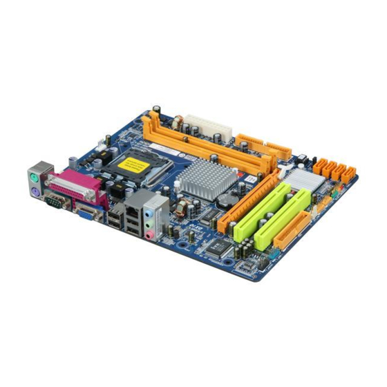
Page 6: Motherboard Layout
Motherboard Manual OTHERBOARD AYOUT CPU_FAN1 ATXPWR2 KBMS1 LGA775 ATXPWR1 CPU1 J USBV1 USB1 RJ45USB1 Intel AUDIO1 BAT1 PEX16_1 Super BI OS Intel JCMOS1 PCI1 ICH7 SATA4 JUSBV2 SATA3 PCI2 Codec SATA2 FDD1 F_AUDIO1 F_COM1 F_USB2 F_USB1 PANEL1 SYS_FAN1 SATA1 Note: ■ represents the 1 pin. -
Page 7: Chapter 2: Hardware Installation
G41D-M7 CHAPTER 2: HARDWARE INSTALLATION (CPU) NSTALLING ENTRAL ROCESSING Special Notice: Remove Pin Cap before installation, and make good preservation for future use. When the CPU is removed, cover the Pin Cap on the empty socket to ensure pin legs won’t be damaged. - Page 8 Motherboard Manual Step 2: Look for the triangular cut edge on socket, and the golden dot on CPU should point forwards this triangular cut edge. The CPU will fit only in the correct orientation. Step 2-1: Step 2-2: Step 3: Hold the CPU down firmly, and then lower the lever to locked position to complete the installation.
-
Page 9: Fan Headers
G41D-M7 FAN H EADERS These fan headers support cooling-fans built in the computer. The fan cable and connector may be different according to the fan manufacturer. Connect the fan cable to the connector while matching the black wire to pin#1. -
Page 10: Installing System Memory
Motherboard Manual NSTALLING YSTEM EMORY A. DDR2 module Unlock a DIMM slot by pressing the retaining clips outward. Align a DIMM on the slot so that the notch on the DIMM matches the break on the Slot. Insert the DIMM vertically and firmly into the slot until the retaining chip snap back in place and the DIMM is properly seated. - Page 11 G41D-M7 B. Memory Capacity DIMM Socket Total Memory DDR2 Module Location Size DDR2_A1 256MB/512MB/1GB/2GB Max is 4GB. DDR2_B1 256MB/512MB/1GB/2GB C. Dual Channel Memory Installation Please refer to the following requirements to activate Dual Channel function: Install memory module of the same density in pairs, shown in the table.
-
Page 12: Connectors And Slots
Motherboard Manual ONNECTORS AND LOTS FDD1: Floppy Disk Connector The motherboard provides a standard floppy disk connector that supports 360K, 720K, 1.2M, 1.44M and 2.88M floppy disk types. This connector supports the provided floppy drive ribbon cables. IDE1: IDE/ATAPI Connector The motherboard has a 32-bit Enhanced PCI IDE Controller that provides PIO Mode 0~4, Bus Master, and Ultra DMA 33/66/100 functionality. - Page 13 G41D-M7 PEX16_1: PCI-Express x16 Slot PCI-Express 1.0a compliant. Maximum theoretical realized bandwidth of 4GB/s simultaneously per direction, for an aggregate of 8GB/s totally. PCI-Express supports a raw bit-rate of 2.5Gb/s on the data pins. 2X bandwidth over the traditional PCI architecture.
-
Page 14: Chapter 3: Headers & Jumpers Setup
Motherboard Manual CHAPTER 3: HEADERS & JUMPERS SETUP OW TO ETUP UMPERS The illustration shows how to set up jumpers. When the jumper cap is placed on pins, the jumper is “close”, if not, that means the jumper is “open”. Pin opened Pin closed Pin1-2 closed... - Page 15 G41D-M7 ATXPWR1: ATX Power Source Connector This connector allows user to connect 24-pin power connector on the ATX power supply. Assignment Assignment +3.3V +3.3V -12V +3.3V Ground Ground PS_ON Ground Ground Ground Ground Ground PW_OK Standby Voltage+5V +12V +12V Ground +3.3V...
- Page 16 Motherboard Manual F_USB1/F_USB2: Headers for USB 2.0 Ports at Front Panel This motherboard provides 2 USB 2.0 headers, which allow user to connect additional USB cable on the PC front panel, and also can be connected with internal USB devices, like USB card reader. Assignment +5V (fused) +5V (fused)
-
Page 17: Clear Cmos Procedures
G41D-M7 JCMOS1: Clear CMOS Header Placing the jumper on pin2-3 allows user to restore the BIOS safe setting and the CMOS data, please carefully follow the procedures to avoid damaging the motherboard. Pin 1-2 Close: Normal Operation (Default). Pin 2-3 Close: Clear CMOS data. -
Page 18: Serial Port Connector
Motherboard Manual JUSBV1/JUSBV2: Power Source Headers for USB Ports Pin 1-2 Close: JUSBV1: +5V for USB ports at USB1/RJ45USB1. JUSBV2: +5V for USB ports at F_USB1/F_USB2. Pin 2-3 Close: JUSBV1: +5V STB for USB ports at USB1/RJ45USB1. JUSBV2: +5V STB for USB ports at F_USB1/F_USB2. Pin 1-2 close JUSBV1 JUSBV2... -
Page 19: Chapter 4: Useful Help
G41D-M7 CHAPTER 4: USEFUL HELP RIVER NSTALLATION After you installed your operating system, please insert the Fully Setup Driver CD into your optical drive and install the driver for better system performance. You will see the following window after you insert the CD The setup guide will auto detect your motherboard and operating system. -
Page 20: Software
Motherboard Manual OFTWARE Installing Software 1. Insert the Setup CD to the optical drive. The drivers installation program would appear if the Autorun function has been enabled. 2. Select Software Installation, and then click on the respective software title. 3. Follow the on-screen instructions to complete the installation. Launching Software After the installation process, you will see the software icon “eHOT Line”... - Page 21 G41D-M7 After filling up this information, click “Send” to send the mail out. A warning dialog would appear asking for your confirmation; click “Send” to confirm or “Do Not Send” to cancel. If you want to save this information to a .txt file, click “Save As…” and then you will see a saving dialog appears asking you to enter file name.
-
Page 22: Bios Update
Motherboard Manual BIOS Update BIOS Update is a convenient utility which allows you to update your motherboard BIOS under Windows system. Show current BIOS information AWARD BIOS AMI BIOS Online Update function Clear CMOS function (Only for AMI BIOS) (Only for AWARD BIOS) Save current BIOS to a .bin file Update BIOS... - Page 23 G41D-M7 <Update BIOS> Before doing this, please download the proper BIOS file from the website. For AWARD BIOS, update BIOS procedure should be run with Clear CMOS function, so please check on Clear CMOS first. Then click Update BIOS button, a dialog will show for asking you backup current BIOS.
- Page 24 Motherboard Manual <Online Update> (for AMI BIOS only) Automatically download and update the latest BIOS via internet; make sure that the computer is connected to the internet before using this function. After clicking on the Online Update button, the utility will search for the latest BIOS from internet.
-
Page 25: Extra Information
G41D-M7 XTRA NFORMATION CPU Overheated If the system shutdown automatically after power on system for seconds, that means the CPU protection function has been activated. When the CPU is over heated, the motherboard will shutdown automatically to avoid a damage of the CPU, and the system may not power on again. - Page 26 Motherboard Manual BIO-Flasher BIO-Flasher is a BIOS flashing utility providing you an easy and simple way to update your BIOS via USB pen drive or floppy disk. The BIO-Flasher is built in the BIOS chip. To enter the utility, press <F12> during the Power-On Self Tests (POST) procedure while booting up.
-
Page 27: Ami Bios Beep Code
G41D-M7 AMI BIOS B Boot Block Beep Codes Number of Beeps Description No media present. (Insert diskette in floppy drive A:) “AMIBOOT.ROM” file not found in root directory of diskette in Insert next diskette if multiple diskettes are used for recovery... -
Page 28: Troubleshooting
Motherboard Manual ROUBLESHOOTING Probable Solution There is no power in the system. Make sure power cable is Power LED does not shine; the securely plugged in. fan of the power supply does not Replace cable. work Contact technical support. Indicator light on keyboard does not shine. - Page 29 G41D-M7 This page is intentionally left bank.
-
Page 30: Appendix: Spec In Other Languages
Motherboard Manual APPENDIX: SPEC IN OTHER LANGUAGES ERMAN Spezifikationen LGA 775 Unterstützt Hyper-Threading / Execute Disable Bit / Intel Core2Quad / Core2Duo / Pentium Enhanced Intel SpeedStep® / Intel Architecture-64 / Dual-Core / Celeron Dual-Core / Celeron Extended Memory 64 Technology / Virtualization 4xx Prozessoren Technology (Maximales Watt: 95W) - Page 31 VGA-Anschluss LAN-Anschluss USB-Anschluss Audioanschluss Platinengröße 190 mm (B) X 244 mm (L) Biostar behält sich das Recht vor , ohne Ankündigung OS-Unterstüt Windows 2000 / XP / Vista 32 / Vista 64 die Unterstützung für ein Betriebssystem zung hinzuzufügen oder zu entfernen.
-
Page 32: French
Motherboard Manual RENCH SPEC LGA 775 Prend en charge les technologies Hyper-Threading / Processeurs Intel Core2Quad / Core2Duo d'exécution de bit de désactivation / Intel SpeedStep® /Pentium Dual-Core / Celeron Dual-Core / optimisée/ d'architecture Intel 64 / de mémoire Celeron 4xx (Watt maximum : 95W) étendue 64 / de virtualisation Bus frontal 800 / 1066 / 1333 MHz Intel G41... - Page 33 Dimensions 190 mm (l) X 244 mm (H) de la carte Biostar se réserve le droit d'ajouter ou de supprimer le Support SE Windows 2000 / XP / Vista 32 / Vista 64 support de SE avec ou sans préavis.
-
Page 34: Italian
Motherboard Manual TALIAN SPECIFICA LGA 775 Supporto di Hyper-Threading / Execute Disable Processore Intel Core2Quad / Bit / Enhanced Intel SpeedStep® / Architettura Core2Duo /Pentium Dual-Core / Intel 64 / Tecnologia Extended Memory 64 / Celeron Dual-Core / Celeron 4xx Tecnologia V irtualization (Watt massimo: 95W) 800 / 1066 / 1333 MHz... - Page 35 Connettore audio Dimension 190 mm (larghezza) x 244 mm i scheda (altezza) Sistemi Biostar si riserva il diritto di aggiungere o Windows 2000 / XP / Vista 32 / Vista operativi rimuovere il supporto di qualsiasi sistema supportati operativo senza preavviso.
-
Page 36: Spanish
Motherboard Manual PANISH Especificación LGA 775 Admite Hyper-Threading / Bit de deshabilitación de Procesador Intel Core2Quad / Core2Duo ejecución / Intel SpeedStep® Mejorado / Intel /Pentium Dual-Core / Celeron Dual-Core / Architecture-64 / Tecnología Extended Memory 64 / Celeron 4xx (Vatio máximo: 95W) Tecnología de virtualización 800 / 1066 / 1333 MHz Conjunto de... - Page 37 190 mm. (A) X 244 Mm. (H) la placa Soporte de Biostar se reserva el derecho de añadir o retirar el sistema Windows 2000 / XP / Vista 32 / Vista 64 soporte de cualquier SO con o sin aviso previo.
-
Page 38: Portuguese
Motherboard Manual ORTUGUESE ESPECIFICAÇÕES LGA 775 Suporta as tecnologias Hyper-Threading / Execute Processador Intel Core2Quad / Core2Duo Disable Bit / Enhanced Intel SpeedStep® / Intel /Pentium Dual-Core / Celeron Dual-Core / Arquitecture -64 / Extended Memory 64 / Virtualization Celeron 4xx (Watt máximo: 95W) 800 / 1066 / 1333 MHz Intel G41 Chipset... - Page 39 Tamanho 190 mm (L) X 244 mm (A) da placa Sistemas A Biostar reserva-se o direito de adicionar ou remover operativos Windows 2000 / XP / Vista 32 / Vista 64 suporte para qualquer sistema operativo com ou sem suportados...
-
Page 40: Polish
Motherboard Manual OLISH SPEC LGA 775 Obsługa Hyper-Threading / Execute Disable Bit / Procesor Intel Core2Quad / Core2Duo Enhanced Intel SpeedStep® / Intel Architecture-64 / Procesor /Pentium Dual-Core / Celeron Dual-Core / Extended Memory 64 Technology / Virtualization Celeron 4xx (Maksymalny Watt: 95W) Technology 800 / 1066 / 1333 MHz Intel G41... - Page 41 Port LAN Port USB Gniazdo audio Wymiary 190 mm (S) X 244 mm (W) płyty Obsluga Biostar zastrzega sobie prawo dodawania lub systemu Windows 2000 / XP / Vista 32 / Vista 64 odwoływania obsługi dowolnego systemu operacyjne operacyjnego bez powiadomienia.
-
Page 42: Russian
Motherboard Manual USSIAN СПЕЦ LGA 775 Поддержка технологий Hyper-Threading / Execute (центральн Процессор Intel Core2Quad / Core2Duo Disable Bit / Enhanced Intel SpeedStep® / Intel ый /Pentium Dual-Core / Celeron Dual-Core / Architecture-64 / Extended Memory 64 Technology / процессор) Celeron 4xx (Максимальный... - Page 43 Гнездо для подключения наушников Размер 190 мм (Ш) X 244 мм (В) панели Biostar сохраняет за собой право добавлять или Поддержка Windows 2000 / XP / Vista 32 / Vista 64 удалять средства обеспечения для OS с или без предварительного уведомления.
-
Page 44: Arabic
Motherboard Manual RABIC اﻟﻤﻮاﺻﻔﺎت LGA 775 ﺗﺪﻋﻢ ﺗﻘﻨﻴﺎتHyper-Threading / Execute Disable Bit / ﻣﻌﺎﻟﺠﺎتIntel Core2Quad / Core2Duo Enhanced Intel SpeedStep® / Intel Architecture-64 / اﻟﻤﻌﺎﻟﺠﺔ وﺣﺪة /Pentium Dual-Core / Celeron Dual-Core / Extended Memory 64 Technology / Virtualization اﻟﻤﺮآﺰیﺔ Celeron 4xx ﺼﻞ... -
Page 45: Pci Express
G41D-M7 اﻟﻤﻮاﺻﻔﺎت ﻋﺪد ﻓﺘﺤﺔ اﻟﻔﺘﺤﺎت ﻋﺪد PCI Express ﻓﺘﺤﺔ ﻋﺪد ﻣﻨﻔﺬ ﻣﺤﺮك أﻗﺮاص ﻣﺮﻥﺔ یﺪﻋﻢ ﻣﺤﺮآﻴﻦ ﻟﻸﻗﺮاص اﻟﻤﺮﻥﺔ ﻋﺪد ()اﺥﺘﻴﺎر ی ّﺔ ﻣﻨﻔﺬ ﺗﺴﻠﺴﻠﻲ ﻋﺪد ﻣﻨﻔﺬ یﺪﻋﻢ آﻞ ﻣﻨﻔﺬ اﺙﻨﻴﻦ ﻣﻦ أﺝﻬﺰةIDE ﻋﺪد SATA ﻣﻨﻔﺬ یﺪﻋﻢ آﻞ ﻣﻨﻔﺬ واﺣﺪ ﻣﻦ أﺝﻬﺰةSATA ﻋﺪد... -
Page 46: Japanese
Motherboard Manual APANESE 仕様 LGA 775 Hyper-Threading / Execute Disable Bit / Enhanced Intel Intel Core2Quad / Core2Duo / Pentium SpeedStep® / Intel Architecture-64 / Extended Dual-Core / Celeron Dual-Core / Celeron Memory 64 Technology / Virtualization Technologyをサ 4xx processor ポートします... - Page 47 G41D-M7 仕様 PCIスロット スロット PCI Express x16スロット フロッピーコネクタ 各コネクタは2つのフロッピードライブをサポートします シリアルポート (任意) IDEコネクタ 各コネクタは2つのIDEデバイスをサポートします SATAコネクタ 各コネクタは1つのSATAデバイスをサポートします フロントパネルコネクタ フロントパネル機能をサポートします フロントオーディオコネクタ フロントパネルオーディオ機能をサポートします オンボードコ CPUファンヘッダ CPUファン電源装置(スマートファン機能を搭載) ネクタ システムファンヘッダ システムファン電源装置 CMOSクリアヘッダ 各コネクタは2つのフロントパネルUSBポートをサポートし USBコネクタ ます 電源コネクタ(24ピン) 電源コネクタ(4ピン) PS/2キーボード PS/2マウス シリアルポート 背面パネル プリンタポート VGAポート LANポート USBポート オーディオジャック...
Need help?
Do you have a question about the G41D-M7 and is the answer not in the manual?
Questions and answers