
Related Manuals for McIntosh C33


Summary of Contents for McIntosh C33
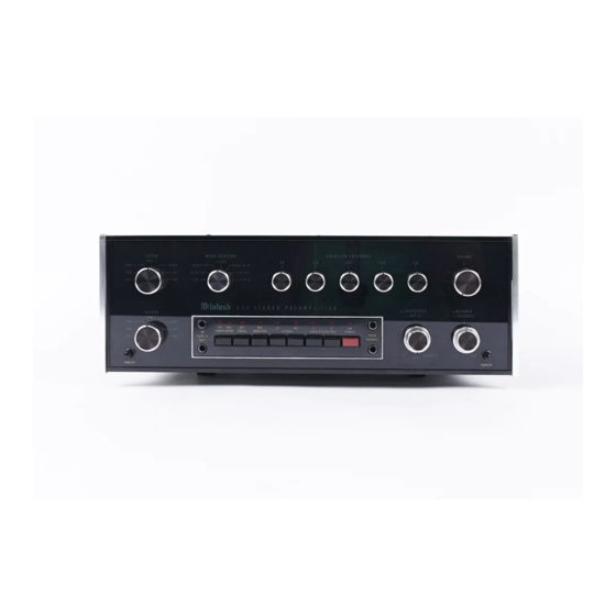
- Page 1 THE MclNTOSH C 33 SOLID STATE STEREO PREAMPLIFIER Reading Time: 43 Minutes Price $2.00...
- Page 2 VARIOUS REGULATORY AGENCIES REQUIRE THAT WE BRING THE FOLLOWING INFORMATION TO YOUR ATTENTION. PLEASE READ IT CAREFULLY. WARNING: TO PREVENT FIRE OR SHOCK HAZARD, DO NOT EXPOSE THIS UNIT TO RAIN OR MOISTURE. The Mclntosh you have purchased is a Model C 33. It has a serial number located on the rear panel of the chassis.
-
Page 3: Table Of Contents
Your C 33 Stereo Preamplifier is designed to perform to its specifications for many years. If you Contents have any questions, please contact: CUSTOMER SERVICE INTRODUCTION Mclntosh Laboratory Inc. SIMPLIFIED BLOCK DIAGRAM 2 Chambers Street INSTALLATION Binghamton, New York 13903-9990 SIMPLIFIED CONNECTING DIAGRAM Phone: 607-723-3512 HOW TO CONNECT... -
Page 4: Introduction
Introduction The Mclntosh C 33 is a super quality, high perfor- a compandor, which permits expansion or com- mance Stereo Preamplifier. Its design has been pression of the dynamic range of program mater- governed by insistence on great flexibility, versatili- ial from either the record tape output or the main ty, low distortion and high performance with long listen output. -
Page 6: Installation
from the top. With adequate ventilation the instru- ment can be mounted in any position. The recom- mended minimum space for installation is 15 inches (38.1 cm) deep, 17 inches (43.2 cm) wide, and 6 in- ches (15.2 cm) high. To install the instrument in a Mclntosh cabinet, follow the instructions that are enclosed with the cabinet. - Page 7 net panel; the short flange is mounted against the use a file to square the corners and smooth any ir- front (face) of the cabinet panel. The screws pass regularities in the cut edges, through the PANLOC bracket flange, the cabinet Install the Mounting Strips panel, and then through the mounting strips In the hardware package you will find two mounting...
-
Page 9: How To Connect
How to Connect Rear panel input jacks are provided for 2 stereo the Right TAPE 1 INPUT jack. Connect a second and turntables, PHONO 1 and PHONO 2; a stereo tuner, third recorder in the same manner to the TAPE 2 IN- TUNER;... - Page 10 Two stereo power amplifiers or two delay units minal closest to the C 33 ground terminal. Connect may be connected in the same fashion to the OUT- the right plus lead to the red OUTPUT R terminal. PUT 1 and OUTPUT 2 jacks. Audio output signal is Resistance of the speaker hookup wire should be supplied to these jacks only when the front panel kept less than 0.5 ohms to avoid losses and...
- Page 11 TAPE FM ANTENNA RECORDER TUNER TAPE RECORDER RECORDER 3 AC POWER TO TAPE RECORDERS, TUNERS, POWER AMPLIFIERS. TOTAL OF 1200 WATTS. FOR MORE AC POWER USE THE SCR SPEAKER CONTROL RELAY AC POWER TURNTABLE #2 AC POWER TURNTABLE #1 CONNECTIONS FOR TUNERS, TURNTABLES, AND TAPE RECORDERS...
- Page 12 MAIN SPEAKERS CUSTOM ENVIRONMENTAL EQUALIZER (FOR M A I N SPEAKERS) NOISE REDUCTION PROCESSOR PLAYBACK RECORD CONNECTIONS FOR POWER AMPLIFIERS AND LOUDSPEAKERS USING MAIN SPEAKERS AND ENVIRONMENTAL EQUALIZER. ALSO SHOWN FOR REMOTE SPEAKERS USING SEPARATE POWER A M P L I F I - ERS AND CONNECTIONS FOR AN EXTERNAL NOISE REDUCTION SIGNAL PROCESSOR.
- Page 13 TO AC LINE REMOTE SPEAKERS (CONTROLLED BY SPEAKER 2 PUSHBUTTON) MAIN SPEAKERS (CONTROLLED BY SPEAKER 1 PUSHBUTTON) TIME D E L A Y UNIT MONITOR AMPLIFIER SPEAKERS CONNECTIONS FOR POWER AMPLIFIERS AND LOUDSPEAKERS TO REPRODUCE USING OPTIONAL SCR-2 SPEAKER CONTROL RELAY. CONNECTIONS ALSO TIME DELAYED SHOWN FOR TIME DELAY UNIT AND MONITOR AMPLIFIER LOUDSPEAKERS.
-
Page 14: Using The Front Panel Controls
Using the Front Panel Controls right output circuits. LISTEN AND RECORD SELECTOR SWITCHES R TO L&R: Connects the right input to both left The LISTEN input se- and right output circuits. lector switch is located STEREO REV: Connects the left input to the right at the upper left on the output circuit and the right input to the left output front panel. - Page 15 Problem Equalizer Correction range. It can be used for making tape recordings or Raise 30 Deep bass to weak for listening to background music. The Compandor All bass weak Raise 30 and 150 can be switched to either the record or listen lines. Voice reinforcement Lower 150 and raise 500 In this way you can make your own recordings using...
- Page 16 (usually between 1.2 and 1.5). Now switch the ex- a. Select the LISTEN input. pander on and off. A change in the average listening b. Increase the VOLUME to a satisfactory level. level will usually be heard at this time. Adjust the c.
-
Page 17: Using The Pushbuttons
Using the Pushbuttons light will be off. When the pushbutton is in, the LF COMPANDOR FILTER is in the circuit and the red light will be on. The COMPANDOR pushbutton connects the com- pandor to either the listen or the record program The filter is effective for all frequencies below 50 Hz line. - Page 18 ed such as rear channel reverberation units, color displays, etc. For example Output 1 or 2 can be con- nected to a reverberation device and then to the C 33 monitor amplifier and a set of rear loudspeakers. (The monitor amplifier switch must be in the EXTER- NAL position.) Rear channel reverberation can then be switched in and out without the need for an extra amplifier.
-
Page 19: Top Panel Information And Secondary Controls
Top Panel Information and Secondary Controls COMPANDOR MANUAL switch must be set in the MANUAL posi- Operation of the LEVEL MATCH and SPEED con- tion. The red POWER pushbutton must be used in- trols is explained on page 13 under the Compandor stead. -
Page 20: Performance Limits And Ratings
Performance Limits and Ratings PERFORMANCE LIMITS MONITOR AMPLIFIER SECTION Performance limits are the maximum deviation CONTINUOUS AVERAGE POWER OUTPUT from perfection permitted for a Mclntosh instru- 20 watts per channel into 8 ohms, from 20Hz to ment. We promise you that when you purchase a 20kHz, at 0.01% maximum harmonic distortion new C 33 from a Mclntosh franchised dealer, it will FREQUENCY RESPONSE... -
Page 21: Performance Charts
Performance Charts FREQUENCY RESPONSE IN: AUX; OUT: MAIN LF AND HF FILTERS MONITOR AMPLIFIER 100K FREQUENCY IN HERTZ LOUDNESS CONTROL RESPONSE FOR VARIOUS CONTROL POSITIONS FREQUENCY IN HERTZ EQUALIZER FREQUENCY RESPONSE CONTROLS SET AT MAXIMUM AND MINIMUM FREQUENCY IN HERTZ RIAA EQUALIZATION CURVE FREQUENCY IN HERTZ -19-... - Page 22 PHONO HARMONIC DISTORTION AT 2.5 VOLTS OUTPUT FREQUENCY IN HERTZ HARMONIC DISTORTION IN: AUX; OUT: MAIN RMS OUTPUT VOLTS INTERMODULATION DISTORTION IN: AUX; OUT: MAIN INPUT FREQUENCY: 60Hz & 7kHz RATIO: 4:1 EQUIVALENT OUTPUT VOLTS MONITOR AMPLIFIER POWER BANDWIDTH AT .02% T.H.D., 8 OHMS 100K FREQUENCY IN HERTZ MONITOR AMPLIFIER HARMONIC...
- Page 23 COMPANDOR LEVEL MATCH RANGE MID ROTATION LEVEL MATCH CONTROL POSITION COMPANDOR EXPANSION AND COMPRESSION CHARACTERISTICS INPUT (dB) COMPANDOR INPUT VOLTAGE LIMIT RATIO CONTROL POSITION -21-...
-
Page 24: Technical Description
Technical Description The simplified block diagram on page 3 and the vent cross talk between inputs. The FET "on" resistance is very low which prevents distortion. The detailed block diagram on page 24 show how the C 33 switching transistors are located right at the input internal circuits are arranged. - Page 25 "from" jack. If no processor is connected the signal SCR conducts a relay closes. This relay turns on passes directly through the jacks. power to the C33 and to the black AC power outlets. A current sensing sensitivity control allows cal- An equalizer amplifier with unity gain follows ibrating the Auto Turn-On circuit to the turntable next.
-
Page 26: Block Diagram
Block Diagram MclNTOSH C 3 3 STE -24-... - Page 27 REO PREAMPLIFIER -25-...
- Page 28 MclNTOSH LABORATORY INC. 2 CHAMBERS ST., BINGHAMTON, N.Y. 13903-9990 607-723-3512 The continuous improvement of its products is the policy of Mclntosh Laboratory Incorporated, who reserves the right to improve design without notice. Printed in U.S.A. 039299 BE032003...
Need help?
Do you have a question about the C33 and is the answer not in the manual?
Questions and answers