Table of Contents
Advertisement
Quick Links
Advertisement
Table of Contents

Related Manuals for Diamond G9/4BF8-N


Summary of Contents for Diamond G9/4BF8-N
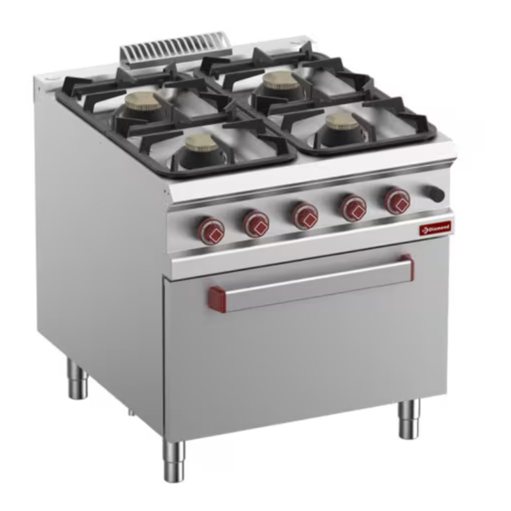
- Page 1 MOD : G9/4BF8-N Production code : DIFB98FGXL 0 9 /2023...
-
Page 2: Table Of Contents
STOVE - SOLID TOP (FLEX BURNER) INSTALLATIONS AND USE INSTRUCTIONS TABLE OF CONTENTS 1-2. GENERAL SAFETY 7. FLEX BURNER INFORMATION 8. REPLACING COMPONENTS 3. POSITIONING AND HANDLING 9. INSTRUCTIONS FOR USE 4. POWER SUPPLY CONNECTIONS MAINTENANCE 5. OPERATIONS FOR COMMISSIONING 11. -
Page 3: General Safety Information
scrapping the appliance. Obligation to use safety shoes. “Heterogeneous” Opera- tor (Operator with limited Other indications. Indica- skills and tasks). Person tions to implement the cor- authorised and employed to ope- rect procedure, non-com- rate the appliance with guards pliance may cause a dangerous active, capable of performing situation. -
Page 4: Operator Training
GENERAL AND SAFETY INFORMATION contents of the envelope, are an inte- by legislation in force in the country of gral part of the initial supply. It must installation; therefore be kept and used appropria- • earthing system in compliance with tely during the entire operational life of standards in force;... - Page 5 GENERAL AND SAFETY INFORMATION rating area for maintenance must be set is responsible for the equipment in its up in such a way that the safety of the original configuration and only for origi- operator is not endangered. The room nal spare parts replacement.
- Page 6 GENERAL AND SAFETY INFORMATION Every technical change has an connections to the mains. effect on the operation or safety The appliance is not designed to of the appliance and must the- work in an explosive atmosphe- refore be performed by technical per- re and as such its installation sonnel of the manufacturer or by tech- and use is categorically prohibited in...
- Page 7 GENERAL AND SAFETY INFORMATION operating “glass” unsiphoned formation. structions have been drawn up for the “Gene- The appliance must only be ric” operator (Operator with limited re- used for the purposes indicat- sponsibilities and tasks). Person au- ed. Any other use must be con- thorised and employed to operate the sidered “IMPROPER”...
-
Page 8: Equipment Required For Installation
GENERAL AND SAFETY INFORMATION locked doors, protective casing. tact with materials at high temperatures. • All the zones within the control units, electrical cabinets and junction boxes. RESIDUAL RISK OF BURNS DUE TO LEAKING OF MATE- • All the zones around the appliance RIAL / This risks remains when in operation when the minimum safe- ty distances are not being respected. -
Page 9: Handling Safety
GENERAL AND SAFETY INFORMATION B-C-D). In the models provided (free cupboard Do not operate any device which bottom), it is possible to remove the • could produce sparks or flames lower surface for installation and main- (Detail B-C-D). tenance operations (eg inspections, Use a means of communication connections, cleaning etc). -
Page 10: Disposal Of Packaging
POSITIONING AND HANDLING given by the pictograms and lette- used to protect the parts. ring on the outer packaging. Be careful not to damage stainless steel surfaces. No not use corrosi- Position the lifting means paying at- ve products, abrasive material or tention to the centre of gravity of the sharp tools. -
Page 11: Power Supply Connections
POSITIONING AND HANDLING permitted), previously made suitable, of including hot combustion fumes coming the appliance. out of the chimney (see identification with High temperatures warning label The tasks of levelling and securing in- and description on page 2), to people clude: adjustment of the appliance as who transit and / or operate within the a single independent unit. - Page 12 POWER SUPPLY CONNECTIONS Do not connect the applian- in force. The extraction hood above ces to networks containing the appliance must be in operation du- gas with carbon monoxide or ring use of the appliance itself. other toxic components The distance between the appliance and the filter of the extraction hood Upon completion of the operations de- must be at least 20 cm.
-
Page 13: Electrical Connection
POWER SUPPLY CONNECTIONS ELECTRICAL CONNECTION It is mandatory to respect the Electrical connection should be per- connection provided by the ma- formed in compliance with the local regulations in force, only by authorised nufacturer, visible on the con- and competent personnel. In the first nection label near the terminal board. -
Page 14: Operations For Commissioning
POWER SUPPLY CONNECTIONS installation country. to the power of the devices installed. The appliance plate “Equipotential” is The electrician preparing the usually on its panel, near the system general electrical system must used for the connection; carry out guarantee a system in conform- the connection after having recogni- ity with the regulations, for what con- zed the same plate (see schematic... - Page 15 OPERATIONS FOR COMMISSIONING vious sections completed, the ap- supply lines upstream the applian- pliance, even if correctly calibrated ce (e.g. Water-Gas-Electrical). during the testing phase, requires partial verification of the parame- STOPPAGE DUE TO FAULTY ters set directly at the place of final OPERATIONS destination.
-
Page 16: Gas Type Changeover
OPERATIONS FOR COMMISSIONING bed above: 3. Dry the surfaces carefully using 1. Close the network locks upstream the non-abrasive material; appliance (Water - Gas - Electric). 4. Wipe a non-abrasive cloth lightly so- 2. Make sure that the drain cocks (if aked with food-safe Vaseline oil over all present) are “Closed”. -
Page 17: Pilot Burner Adjustment
GAS TYPE CHANGEOVER 4. Screw the new injector. screwed hard (see Gas Table). Open the cut-off cock upstream the Make sure there are no gas le- machine. In case of screw replacement put ADJUSTMENT OF MAIN BURNER a tampering detecting seal on it at - see SECT. -
Page 18: Replacing Components
REPLACING COMPONENTS Solid top 700: Unscrew the retaining Before proceeding with the ope- rations, see “General safety infor- nut at the crosspiece and the pilot group mation”. (Fig. 4/A) / Remove the burner/Position the new burner/ Tighten the burner at the crosspiece and the pilot group see SECT. -
Page 19: Bulb Replacement
REPLACING COMPONENTS SAFETY THERMOSTAT BULB REPLACEMENT 1. Disconnect the electrical con- REPLACEMENT 1. Unscrew the thermostat from the nections support ( 2. Fit the new bulb 2. Remove the bulb from the support 3. Reconnect the cables 3. Screw the new thermostat and in- Check the gas seal with the sert the new bulb into the support appropriate instruments and... - Page 20 INSTRUCTIONS FOR USE 1. Solid top: T ≤ 250 ° C / Lower A). Simultaneously press the piezoe- temperature at the hottest point lectric button several times (Fig.3 De- 2. Mijotage: T ≤ 150 ° C / Lower tail B) until the pilot light is lit. temperature at the hottest point Release the knob after about 20”...
-
Page 21: Maintenance
INSTRUCTIONS FOR USE the cooking compartment/hob (Fig. 5). The appliance must be cleaned For the oven appliance, open the door regularly and every incrustation of the cooking compartment and place or food deposit removed. See the container in the specific housing. chapter: “Maintenance”. - Page 22 MAINTENANCE When putting these parts back, the inside and outside of the applian- do not invert the position of the ce (use detergents on the market for burners and burner caps. cleaning steel, glass and enamel). DAILY CLEANING OF SOLID TOP Carefully read the indications carried on the labels of the pro- Use a standard sprayer...
- Page 23 MAINTENANCE Air out the appliances and rooms When finished, rinse the cooking com- regularly partment abundantly with tap water (do not use pressurised direct water or SUMMARISED TABLE / steam cleaners jets for cleaning ope- OPERATION - FREQUENCY rations). When these operations have Before proceeding with the been performed successfully, dry the operations, see chap.2 “Duties...
-
Page 24: Operation
MAINTENANCE OPERATION FREQUENCY Cleaning appliance Daily Cleaning parts in contact Daily with foodstuff / hotplates Cleaning at commissioning Upon arrival after installation Cleaning flue Yearly Checking thermostat In case of need - Yearly Greasing the gas taps In case of need Checking / Replacing gas In case of need supply pipes... -
Page 25: Deactivation And Scrapping Of Appliance
WASTE DISPOSAL Before commencing dismant- ling of the appliance, ensure DEACTIVATION AND around the appliance a space SCRAPPING OF APPLIANCE that is large enough and arranged Obligation of disposing of ma- in such a way as to allow all move- terials using the legislative ments without risk.
Need help?
Do you have a question about the G9/4BF8-N and is the answer not in the manual?
Questions and answers