Asus PRIME H310-PLUS Manual
- Manual (27 pages) ,
- Quick start manual (2 pages)
Advertisement
Conventions used in this guide
To ensure that you perform certain tasks properly, take note of the following symbols used throughout this manual.
 DANGER/WARNING: Information to prevent injury to yourself when completing a task.

Information to prevent damage to the components when completing a task.

Instructions that you MUST follow to complete a task.
NOTE:
Tips and additional information to help you complete a task.
Typography
| Bold text | Indicates a menu or an item to select. |
| Italics | Used to emphasize a word or a phrase. |
| <Key> | Keys enclosed in the less-than and greater-than sign means that you must press the enclosed key. Example: <Enter> means that you must press the Enter or Return key. |
| <Key1> + <Key2> + <Key3> | If you must press two or more keys simultaneously, the key names are linked with a plus sign (+). |
Package contents
Check your motherboard package for the following items.
| Motherboard | ASUS PRIME H310-PLUS motherboard |
| Cables | 2 x Serial ATA 6.0 Gb/s cables |
| Accessories | 1 x I/O Shield 1 x M.2 Screw package |
| Application DVD | Support DVD |
| Documentation | User Guide |
NOTE:
If any of the above items is damaged or missing, contact your retailer.
PRIME H310-PLUS specifications summary
| CPU | LGA1151 socket for 8th Generation Intel® CoreTM, i7/i5/i3/Pentium®, and Celeron® Processors Supports Intel® 14nm CPU Supports Intel® Turbo Boost Technology 2.0* * Intel® Turbo Boost Technology 2.0 support depends on the CPU types. ** Refer to www.asus.com for Intel® CPU support list. |
| Chipset | Intel® H310 Chipset |
| Memory | 2 x DIMMs, maximum. 32GB DDR4 2666/2400/2133MHz, Non-ECC, un-buffered memory modules Dual-channel memory architecture Supports Intel® Extreme Memory Profile (XMP) * The maximum memory frequency supported varies by processor. ** DDR4 2666MHz and higher memory modules will run at max. 2666MHz on Intel® 8th Gen. 6-core or higher processors. *** Refer to www.asus.com for the latest Memory QVL (Qualified Vendors List). |
| Graphics | Integrated graphics processor - Intel® HD Graphics support
Maximum shared memory of 1024 MB |
| Expansion slots | 1 x PCI Express 3.0/2.0 x16 slot (at x16 mode) 2 x PCI Express 2.0 x1 slots 3 x PCI slots |
| Storage | Intel® H310 Chipset
* When a device in SATA mode is installed on the M.2 socket, SATA_2 port can not be used. |
| LAN | Realtek® 8111H Gigabit LAN supports LANGuard |
| USB | Intel® H310 Chipset
|
| Audio | Realtek® ALC887 8-channel* High Definition Audio CODEC
* Use a chassis with HD audio module in the front panel to support an 8-channel audio output. |
| ASUS special features | ASUS 5X Protection III
Superb Performance
Gaming Scenario
ASUS Exclusive Features
EZ DIY
|
| ASUS quiet thermal solution | Quiet Thermal Design
|
| Rear panel I/O ports | 1 x PS/2 keyboard/mouse combo port 1 x LPT port 1 x COM port 1 x D-Sub port 1 x HDMI port 2 x USB 3.1 Gen 1 (up to 5Gbps) ports (blue, Type A) 2 x USB 2.0/1.1 ports 1 x LAN (RJ-45) port 3-Jack 8-channel Audio I/O ports |
| Internal connectors | 1 x USB 3.1 Gen 1 (up to 5Gbps) connector supports additional 2 USB 3.1 Gen 1 ports (19-pin) 2 x USB 2.0/1.1 connectors support additional 4 USB 2.0/1.1 ports 4 x SATA 6.0Gb/s connectors (gray) 1 x M.2 Socket 3 for M Key, type 2242/2260/2280 storage devices support (SATA mode & PCIE x 2 mode) 1 x 4-pin CPU Fan connector for 4-pin (PWM mode) coolers control 2 x 4-pin Chassis Fan connectors for 3-pin (DC mode) and 4-pin (PWM mode) coolers control 1 x COM header 1 x RGB header 1 x Front panel audio connector (AAFP) 1 x S/PDIF Out connector 1 x 24-pin EATX power connector 1 x 4-pin ATX 12V power connector 1 x System panel connector (20-5 pin) 1 x Clear CMOS jumper (2-pin) |
| BIOS features | 128 Mb Flash ROM, UEFI AMI BIOS, PnP, SM BIOS 3.1, ACPI 6.1, Multilanguage BIOS, ASUS EZ Flash 3, CrashFree BIOS 3, F6 Qfan Control, F3 My Favorites, Last Modified log, F12 PrintScreen, and ASUS DRAM SPD (Serial Presence Detect) memory information |
| Manageability | WOL by PME, PXE |
| Support DVD | Drivers ASUS utilities ASUS EZ Update Anti-virus software (OEM version) |
| OS support | Windows® 10 (64-bit) |
| Form factor | ATX form factor: 12 in x 7.5 in (30.5 cm x 19 cm) |
NOTE: Specifications are subject to change without notice.
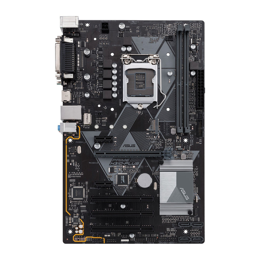
Product introduction
Motherboard overview
- Unplug the power cord from the wall socket before touching any component.
- Before handling components, use a grounded wrist strap or touch a safely grounded object or a metal object, such as the power supply case, to avoid damaging them due to static electricity.
- Before you install or remove any component, ensure that the ATX power supply is switched off or the power cord is detached from the power supply. Failure to do so may cause severe damage to the motherboard, peripherals, or components.

Scan the QR code to get the detailed pin definitions.

- ATX power connectors (24-pin EATXPWR, 4-pin ATX12V)
Correctly orient the ATX power supply plugs into these connectors and push down firmly until the connectors completely fit.
![]()
- For a fully configured system, we recommend that you use a power supply unit (PSU) that complies with ATX 12 V Specification 2.0 (or later version) and provides a minimum power of 350 W. This PSU type has 24-pin and 4-pin power plugs.
- We recommend that you use a PSU with higher power output when configuring a system with more power-consuming devices or when you intend to install additional devices. The system may become unstable or may not boot up if the power is inadequate.
- If you are uncertain about the minimum power supply requirement for your system, refer to the Recommended Power Supply Wattage Calculator at http://support.asus.com/PowerSupplyCalculator/PSCalculator.aspx?SLanguage=en-us for details.
- CPU and chassis fan connectors (4-pin CPU_FAN, 4-pin CHA_FAN1/2)
Connect the fan cables to the fan connectors on the motherboard, ensuring that the black wire of each cable matches the ground pin of the connector.
![]()
Do not forget to connect the fan cables to the fan connectors. Insufficient air flow inside the system may damage the motherboard components. These are not jumpers! Do not place jumper caps on the fan connectors! The CPU_FAN connector supports a CPU fan of maximum 0.5A (12 W) fan power. - Intel® LGA1151 CPU socket
Install Intel® LGA1151 CPU into this surface mount LGA1151 socket, which is designed for 8th Generation Intel® Core™ i7/i5/i3, Pentium®, and Celeron® processors.
NOTE:
For more details, refer to Central Processing Unit (CPU). - DDR4 DIMM slots
Install 2 GB, 4 GB, 8 GB, and 16 GB unbuffered non-ECC DDR4 DIMMs into these DIMM sockets.
NOTE:
For more details, refer to System memory. - USB 3.1 Gen 1 (up to 5Gbps) connector (20- 1pin U31G1_12)
Connect a USB 3.1 Gen 1 module to this connector for additional USB 3.1 Gen 1 front or rear panel ports. This connector complies with USB 3.1 Gen 1 specifications and provides faster data transfer speeds of up to 5 Gbps, faster charging time for USB-chargeable devices, optimized power efficiency, and backward compatibility with USB 2.0. - M.2 socket 3
![]()
This socket allows you to install an M.2 (NGFF) SSD module.
NOTE:- This M.2 socket supports M Key and 2242/2260/2280 storage devices.
- When a device in SATA mode is installed on the M.2 socket, SATA_2 port can not be used.
- Clear RTC RAM (2-pin CLRTC)
![]()
This header allows you to clear the CMOS RTC RAM data of the system setup information such as date, time, and system passwords.
To erase the RTC RAM:- Turn OFF the computer and unplug the power cord.
- Use a metal object such as a screwdriver to short the two pins.
- Plug the power cord and turn ON the computer.
- Hold down the <Del> key during the boot process and enter BIOS setup to re-enter data.


NOTE:
If the steps above do not help, remove the onboard battery and short the two pins again to clear the CMOS RTC RAM data. After clearing the CMOS, reinstall the battery.
- Intel® H310 Serial ATA 6.0Gb/s connectors (7-pin SATA6G_1~4)
These connectors connect to Serial ATA 6.0 Gb/s hard disk drives via Serial ATA 6.0 Gb/s signal cables. - System panel connector (20-5 pin PANEL)
This connector supports several chassis-mounted functions. - USB 2.0 connectors (10-1 pin USB78, USB914)
Connect a USB module cable to any of these connectors, then install the module to a slot opening at the back of the system chassis. These USB connectors comply with USB 2.0 specifications and support up to 480Mbps connection speed. - RGB header
This header is for RGB LED strips.
![]()
The RGB header supports 5050 RGB multi-color LED strips (12V/G/R/B), with a maximum power rating of 3A (12V), and no longer than 3 m.
![]()
Before you install or remove any component, ensure that the ATX power supply is switched off or the power cord is detached from the power supply. Failure to do so may cause severe damage to the motherboard, peripherals, or components.
NOTE:- Actual lighting and color will vary with LED strip.
- If your LED strip does not light up, check if the RGB LED extension cable and the RGB LED strip is connected in the correct orientation, and the 12V connector is aligned with the 12V header on the motherboard.
- The LED strip will only light up when the system is operating.
- The LED strip is purchased separately.
- Serial port connector (10-1 pin COM)
Connect the serial port module cable to this connector, then install the module to a slot opening at the back of the system chassis. - Digital audio connector (4-1 pin SPDIF_OUT)
![]()
Connect the S/PDIF Out module cable to this connector, then install the module to a slot opening at the back of the system chassis. - Front panel audio connector (10-1 pin AAFP)
This connector is for a chassis-mounted front panel audio I/O module that supports HD Audio standard. Connect one end of the front panel audio I/O module cable to this connector.
![]()
- We recommend that you connect a high-definition front panel audio module to this connector to avail of the motherboard's high-definition audio capability.
- If you want to connect a high-definition front panel audio module to this connector, set the Front Panel Type item in the BIOS setup to [HD Audio]. By default, this connector is set to [HD Audio].
- PCI slots
The PCI slots support cards such as LAN card, SCSI card, USB card, and other cards that comply with the PCI specifications. - PCI Express 2.0 x1 slots
This motherboard has two PCI Express 2.0 x1 slots that support PCI Express x1 network cards, SCSI cards, and other cards that comply with the PCI Express specifications. - PCI Express 3.0/2.0 x16 slot
This motherboard has a PCI Express 3.0/2.0 x16 slot that supports PCI Express 3.0/2.0 x16 graphic cards complying with the PCI Express specifications.

Rear panel connectors

- PS/2 Mouse/Keyboard combo port. This port connects to a PS/2 mouse or PS/2 keyboard.
- LPT port. This port supports devices such as a printer. LPT standardizes as IEEE 1284, which is the parallel port interface on IBM PC-compatible computers.
- LAN (RJ-45) port. This port allows Gigabit connection to a Local Area Network (LAN) through a network hub.
LAN port LED indications
![]()
Activity/Link LED Status Description Off No link Orange Linked Orange (Blinking) Data activity Orange (Blinking then steady) Ready to wake up from S5 mode Speed LED Status Description OFF 10Mbps connection ORANGE 100Mbps connection GREEN 1Gbps connection - Line In port (light blue). This port connects to the tape, CD, DVD player, or other audio sources.
- Line Out port (lime). This port connects to a headphone or a speaker. In the 4.1, 5.1and 7.1-channel configurations, the function of this port becomes Front Speaker Out.
- Microphone port (pink). This port connects to a microphone.
NOTE:
Refer to the audio configuration table for the function of the audio ports in 2.1, 4.1, 5.1, or 7.1-channel configuration.

Audio 2.1, 4.1, 5.1 or 7.1-channel configuration
| Port | Headset 2.1-channel | 4.1-channel | 5.1-channel | 7.1-channel |
| Light Blue (Rear panel) | Line In | Rear Speaker Out | Rear Speaker Out | Rear Speaker Out |
| Lime (Rear panel) | Line Out | Front Speaker Out | Front Speaker Out | Front Speaker Out |
| Pink (Rear panel) | Mic In | Mic In | Bass/Center | Bass/Center |
| Lime (Front panel) | - | - | - | Side Speaker Out |
NOTE:
To configure a 7.1-channel audio output:
Use a chassis with HD audio module in the front panel to support a 7.1-channel audio output.
- USB 3.1 Gen 1 (up to 5Gbps) ports. These 9-pin Universal Serial Bus (USB) ports are for USB 3.1 Gen 1 devices.
NOTE:- USB 3.1 Gen 1 devices can only be used for data storage.
- We strongly recommend that you connect USB 3.1 Gen 1 devices to USB 3.1 Gen 1 ports for faster and better performance from your USB 3.1 Gen 1 devices.
- Due to the design of the Intel ® 300 series chipset, all USB devices connected to the USB 2.0 and USB 3.1 Gen 1 ports are controlled by the xHCI controller. Some legacy USB devices must update their firmware for better compatibility.
- HDMI port. This port is for a High-Definition Multimedia Interface (HDMI) connector, and is HDCP compliant allowing playback of HD DVD, Blu-ray, and other protected content.
- Video Graphics Adapter (VGA) port. This 15-pin port is for a VGA monitor or other VGA-compatible devices.
- Serial port connector (COM). This port connects a modem, or other devices that conform with serial specification.
- USB 2.0/1.1 ports. These 4-pin Universal Serial Bus (USB) ports are for USB 2.0/1.1 devices.
Central Processing Unit (CPU)
This motherboard comes with a surface mount LGA1151 socket designed for the 8th Generation Intel® Core™ i7/Core™ i5/Core™ i3, Pentium®, and Celeron® processors.

Unplug all power cables before installing the CPU.
- Ensure that you install the correct CPU designed for the LGA1151 socket only. DO NOT install a CPU designed for LGA1150, LGA1155 and LGA1156 sockets on the LGA1151 socket.
- Upon purchase of the motherboard, ensure that the PnP cap is on the socket and the socket contacts are not bent. Contact your retailer immediately if the PnP cap is missing, or if you see any damage to the PnP cap/socket contacts/motherboard components.
- Keep the cap after installing the motherboard. ASUS will process Return Merchandise Authorization (RMA) requests only if the motherboard comes with the cap on the LGA1151 socket.
- The product warranty does not cover damage to the socket contacts resulting from incorrect CPU installation/removal, or misplacement/loss/incorrect removal of the PnP cap.
Installing the CPU

Apply the Thermal Interface Material to the CPU heatsink and CPU before you install the heatsink and fan if necessary.
System memory
Overview
This motherboard comes with two Double Data Rate 4 (DDR4) Dual Inline Memory Module (DIMM) sockets. A DDR4 module is notched differently from a DDR, DDR2, or DDR3 module. DO NOT install a DDR, DDR2, or DDR3 memory module to the DDR4 slot.

| Channel | Sockets |
| Channel A | DIMM_A1* |
| Channel B | DIMM_B1* |
- You may install varying memory sizes in Channel A and Channel B. The system maps the total size of the lower-sized channel for the dual-channel configuration. Any excess memory from the higher-sized channel is then mapped for single-channel operation.
- Always install DIMMs with the same CAS latency. For optimal compatibility, we recommend that you install memory modules of the same version or date code (D/C) from the same vendor. Check with the retailer to get the correct memory modules.
- DDR4 2666MHz and higher memory modules will run at max. 2666MHz on Intel Gen. 6-core or higher processors.
- Memory modules with memory frequency higher than 2133 MHz and its corresponding timing or the loaded X.M.P. Profile is not the JEDEC memory standard. The stability and compatibility of these memory modules depend on the CPU's capabilities and other installed devices.
NOTE:
- The default memory operation frequency is dependent on its Serial Presence Detect (SPD), which is the standard way of accessing information from a memory module. Under the default state, some memory modules for overclocking may operate at a lower frequency than the vendor-marked value.
- Refer to www.asus.com for the latest Memory QVL (Qualified Vendors List).
Recommended memory configuration

Installing a DIMM

To remove a DIMM

BIOS information
- Before using the ASUS CrashFree BIOS 3 utility, rename the BIOS file in the removable device into PH310PS.CAP.
BIOS setup program
Use the BIOS Setup program to update the BIOS or configure its parameters. The BIOS screens include navigation keys and brief online help to guide you in using the BIOS Setup program.
Entering BIOS Setup at startup
To enter BIOS Setup at startup:
Press <Delete> or <F2> during the Power-On Self Test (POST). If you do not press <Delete> or <F2>, POST continues with its routines.
Entering BIOS Setup after POST
To enter BIOS Setup after POST:
Press <Ctrl>+<Alt>+<Del> simultaneously.
Press the reset button on the system chassis.
Press the power button to turn the system off then back on. Do this option only if you failed to enter BIOS Setup using the first two options.
Using the power button, reset button, or the <Ctrl>+<Alt>+<Del> keys to force reset from a running operating system can cause damage to your data or system. We recommend you always shut down the system properly from the operating system.
- The BIOS setup screens shown in this section are for reference purposes only, and may not exactly match what you see on your screen.
- Visit the ASUS website at www.asus.com to download the latest BIOS file for this motherboard.
- If the system becomes unstable after changing any BIOS setting, load the default settings to ensure system compatibility and stability. Select the Load Optimized Defaults item under the Exit menu or press hotkey F5.
- If the system fails to boot after changing any BIOS setting, try to clear the CMOS and reset the motherboard to the default value. See section Motherboard overview for information on how to erase the RTC RAM.
BIOS menu screen
The BIOS setup program can be used under two modes: EZ Mode and Advanced Mode. Press <F7> to change between the two modes.
EZ Mode
By default, the EZ Mode screen appears when you enter the BIOS setup program. The EZ Mode provides you an overview of the basic system information, and allows you to select the display language, system performance mode, fan profile and boot device priority. To access the Advanced Mode, click Advanced Mode(F7) or press <F7>.
NOTE:
The default screen for entering the BIOS setup program can be changed. Go to the Setup Mode item under the Boot menu.

NOTE:
The boot device options vary depending on the devices you installed to the system.
Advanced Mode
The Advanced Mode provides advanced options for experienced end-users to configure the BIOS settings. The figure below shows an example of the Advanced Mode. Refer to the following sections for the detailed configurations.
NOTE:
To access the EZ Mode, click EzMode(F7) or press <F7>.

Search on FAQ
Move your mouse over this button to show a QR code. Scan this QR code with your mobile device to connect to the ASUS BIOS FAQ web page. You can also scan the QR code below.

Exit menu
The Exit menu items allow you to load the optimal default values for the BIOS items, and save or discard your changes to the BIOS items.

Load Optimized Defaults
This option allows you to load the default values for each of the parameters on the Setup menus. When you select this option or if you press <F5>, a confirmation window appears. Select OK to load the default values.
Save Changes & Reset
Once you are finished making your selections, choose this option from the Exit menu to ensure the values you selected are saved. When you select this option or if you press <F10>, a confirmation window appears. Select OK to save changes and exit.
Discard Changes & Exit
This option allows you to exit the Setup program without saving your changes. When you select this option or if you press <Esc>, a confirmation window appears. Select OK to discard changes and exit.
Launch EFI Shell from USB drives
This option allows you to attempt to launch the EFI Shell application (shellx64.efi) from one of the available USB devices.
Safety information
Electrical safety
- To prevent electrical shock hazard, disconnect the power cable from the electrical outlet before relocating the system.
- When adding or removing devices to or from the system, ensure that the power cables for the devices are unplugged before the signal cables are connected. If possible, disconnect all power cables from the existing system before you add a device.
- Before connecting or removing signal cables from the motherboard, ensure that all power cables are unplugged.
- Seek professional assistance before using an adapter or extension cord. These devices could interrupt the grounding circuit.
- Ensure that your power supply is set to the correct voltage in your area. If you are not sure about the voltage of the electrical outlet you are using, contact your local power company.
- If the power supply is broken, do not try to fix it by yourself. Contact a qualified service technician or your retailer.
Operation safety
- Before installing the motherboard and adding components, carefully read all the manuals that came with the package.
- Before using the product, ensure all cables are correctly connected and the power cables are not damaged. If you detect any damage, contact your dealer immediately.
- To avoid short circuits, keep paper clips, screws, and staples away from connectors, slots, sockets and circuitry.
- Avoid dust, humidity, and temperature extremes. Do not place the product in any area where it may be exposed to moisture.
- Place the product on a stable surface.
- If you encounter technical problems with the product, contact a qualified service technician or your retailer.
ASUS contact information
ASUSTeK COMPUTER INC.
Address: 4F, No. 150, Li-Te Road, Peitou, Taipei 112, Taiwan
Telephone: +886-2-2894-3447
Fax: +886-2-2890-7798
Web site: www.asus.com
Technical Support
Telephone: +86-21-38429911
Fax: +86-21-5866-8722, ext. 9101#
Online support: http://qr.asus.com/techserv
ASUS COMPUTER INTERNATIONAL (America)
Address: 800 Corporate Way, Fremont, CA 94539, USA
Telephone: +1-510-739-3777
Fax: +1-510-608-4555
Web site: http://www.asus.com/us/
Technical Support
Support fax: +1-812-284-0883
Telephone: +1-812-282-2787
Online support: http://qr.asus.com/techserv
ASUS COMPUTER GmbH (Germany and Austria)
Address: Harkort Str. 21-23, 40880 Ratingen, Germany
Fax: +49-2102-959931
Web site: http://www.asus.com/de
Online contact: http://eu-rma.asus.com/sales
Technical Support
Telephone: +49-2102-5789555
Support Fax: +49-2102-959911
Online support: http://qr.asus.com/techserv
Documents / Resources
References
Download manual
Here you can download full pdf version of manual, it may contain additional safety instructions, warranty information, FCC rules, etc.
Advertisement


Need help?
Do you have a question about the PRIME H310-PLUS and is the answer not in the manual?
Questions and answers