Asus PRIME H510M-A Manual
- Manual (34 pages) ,
- Quick start manual (2 pages) ,
- User manual (34 pages)
Advertisement
.
About this guide
This user guide contains the information you need when installing and configuring the motherboard.
How this guide is organized
This guide contains the following parts:
- Chapter 1: Product Introduction
This chapter describes the features of the motherboard and the new technology it supports. It includes descriptions of the switches, jumpers, and connectors on the motherboard. - Chapter 2: BIOS Information
This chapter tells how to boot into the BIOS, and upgrade BIOS using the EZ Flash Utility.
Where to find more information
Refer to the following sources for additional information and for product and software updates.
- ASUS website
The ASUS website provides updated information on ASUS hardware and software products. Refer to the ASUS contact information. - Optional documentation
Your product package may include optional documentation, such as warranty flyers, that may have been added by your dealer. These documents are not part of the standard package.
Conventions used in this guide
To ensure that you perform certain tasks properly, take note of the following symbols used throughout this manual.

CAUTION: Information to prevent damage to the components and injuries to yourself when trying to complete a task.

IMPORTANT: Instructions that you MUST follow to complete a task.
 NOTE: Tips and additional information to help you complete a task.
Package contents
Check your motherboard package for the following items.
| Motherboard | 1 x PRIME H510M-A WIFI motherboard |
| Cables | 2 x SATA 6Gb/s cables |
| Miscellaneous | 1 x ASUS Wi-Fi moving antennas 1 x I/O Shield 1 x M.2 Rubber package 1 x M.2 SSD screw package |
| Application DVD | 1 x Support DVD |
| Documentation | 1 x User manual |
NOTE: If any of the above items is damaged or missing, contact your retailer.
PRIME H510M-A WIFI specifications summary
| CPU | Intel® Socket LGA1200 for 11th Gen Intel® Core™ Processors & 10th Gen Intel® Core™, Pentium® Gold and Celeron® Processors* Supports Intel® 14 nm CPU Supports Intel® Turbo Boost Technology 2.0 and Intel® Turbo Boost Max Technology 3.0** * Refer to www.asus.com for CPU support list. ** Intel® Turbo Boost Max Technology 3.0 support depends on the CPU types. |
| Chipset | Intel® H510 Chipset |
| Memory | 2 x DIMM, Max. 64GB, DDR4 3200(OC)/2933/2800/2666/2400/2133 MHz Non-ECC, Un-buffered Memory* * 10th Gen Intel® Core™ i7/i9 processors support 2933/2800/2666/2400/2133 natively, others will run at the maximum transfer rate of DDR4 2666MHz. |
| Graphics | 1 x DisplayPort 1.4** * Graphics specifications may vary between CPU types. |
| Expansion Slots | Intel® 11th & 10th Gen Processors
Intel® H510 Chipset |
| Storage | Total supports 1 x M.2 slot and 4 x SATA 6Gb/s ports * The M.2 slot shares bandwidth with the SATA6G_2 port. When a device in SATA mode is installed on the M.2 socket, the SATA6G_2 port cannot be used. |
| Ethernet | 1 x Intel® I219-V 1Gb Ethernet |
| Wireless & Bluetooth | Wi-Fi 5 Wi-Fi 5 (802.11 a/b/g/n/ac) Supports 2.4/5GHz frequency band Bluetooth v5.1 |
| USB | Rear USB (Total 6 ports) Front USB (Total 5 ports) |
| Audio | Realtek ALC 897/887 7.1 Surround Sound High Definition Audio CODEC*
Audio Features
* A chassis with an HD audio module in the front panel is required to support 7.1 Surround Sound audio output. |
| Back Panel I/O Ports | 2 x USB 3.2 Gen 1 ports (2 x Type-A) 4 x USB 2.0 ports (4 x Type-A) 1 x DisplayPort 1 x D-Sub port 1 x HDMI™ port 1 x ASUS Wi-Fi Module 1 x Intel® I219-V 1Gb Ethernet port 3 x Audio jacks 1 x PS/2 Keyboard (purple) port 1 x PS/2 Mouse (green) port |
| Internal I/O Connectors | Fan and Cooling related Power related |
| Internal I/O Connectors | Storage related USB 1 x USB 3.2 Gen 1 header supports additional 2 USB 3.2 Gen 1 ports Miscellaneous |
| Special Features | ASUS 5X PROTECTION III
ASUS Q-Design
ASUS Thermal Solution
AURA Sync
|
| Software Features | ASUS Exclusive Software Armoury Crate
AI Suite 3
ASUS CPU-Z |
| Software Features | MyAsus UEFI BIOS
|
| BIOS | 128 Mb Flash ROM, UEFI AMI BIOS |
| Manageability | WOL by PME, PXE |
| Operating System | Windows® 10 64-bit |
| Form Factor | mATX Form Factor 8.9 inch x 8.3 inch (22.6 cm x 21.1 cm) |
NOTE:
- Specifications are subject to change without notice. Please refer to the ASUS website for the latest specifications.
- MyASUS offers a variety of support features such as helping to troubleshoot issues, optimizing product performance, integrating ASUS software, and recovery drive creation. Please scan the QR Code for installation guide and FAQ.
![]()

Connectors with shared bandwidth

| Configuration | 1 | 2 | |
| A | M.2 | PCIe x4 | SATA |
| SATA6G_2 | V | - | |
NOTE:
- The M.2 slot shares bandwidth with the SATA6G_2 port.
- When a device in SATA mode is installed on the M.2 socket, the SATA6G_2 port cannot be used.
Product Introduction
Before you proceed
Take note of the following precautions before you install motherboard components or change any motherboard settings.
- Unplug the power cord from the wall socket before touching any component.
- Before handling components, use a grounded wrist strap or touch a safely grounded object or a metal object, such as the power supply case, to avoid damaging them due to static electricity.
- Before you install or remove any component, ensure that the ATX power supply is switched off or the power cord is detached from the power supply. Failure to do so may cause severe damage to the motherboard, peripherals, or components.
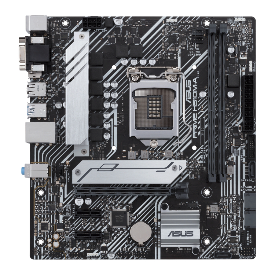
Motherboard overview

Unplug the power cord before installing or removing the motherboard. Failure to do so can cause you physical injury and damage motherboard components.
Layout contents
- CPU socket
The motherboard comes with a LGA1200 socket designed for 11th Gen Intel® Core™ Processors & 10th Gen Intel® CoreTM, Pentium® Gold and Celeron® Processors.
![warning]() NOTE: For more details, refer to Central Processing Unit (CPU).
NOTE: For more details, refer to Central Processing Unit (CPU). - DDR4 DIMM slots/The motherboard comes with Dual Inline Memory Modules (DIMM) slots designed for DDR4 (Double Data Rate 4) memory modules.
![warning]() NOTE: For more details, refer to System memory.
NOTE: For more details, refer to System memory. - Expansion slots
This motherboard supports one PCIe x16 graphics card and two PCIe 3.0 x1 network cards, SCSI cards and other cards that comply with the PCI Express specification. - Fan headers
The Fan headers allow you to connect fans to cool the system.
![]()
- Power connectors
These Power connectors allow you to connect your motherboard to a power supply. The power supply plugs are designed to fit in only one orientation. Find the proper orientation and push down firmly until the power supply plugs are fully inserted.

Ensure to connect the 8-pin power plug.
- For a fully configured system, we recommend that you use a power supply unit (PSU) that complies with ATX 12V Specification 2.0 (or later version) and provides a minimum power of 350W.
- We recommend that you use a PSU with a higher power output when configuring a system with more power-consuming devices. The system may become unstable or may not boot up if the power is inadequate.
- If you are uncertain about the minimum power supply requirement for your system, we recommend you to refer to online resources for Power Supply Wattage Calculator.
- M.2 slot (Key M)
The M.2 slot allows you to install an M.2 device such as an M.2 SSD module.
![warning]() NOTE:
NOTE: - The M.2 slot supports PCIE 3.0 x4 and SATA modes M Key design and type 2242/2260/2280 storage devices.
- The M.2 slot shares bandwidth with the SATA6G_2 port. When a device in SATA mode is installed on the M.2 socket, the SATA6G_2 port cannot be used.
- SATA 6Gb/s connectors
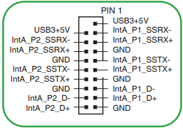
The SATA 6Gb/s connectors allow you to connect SATA devices such as optical disc drives and hard disk drives via SATA cables. - USB 3.2 Gen 1 header
The USB 3.2 Gen 1 header allows you to connect a USB 3.2 Gen 1 module for additional USB 3.2 Gen 1 ports. The USB 3.2 Gen 1 header provides data transfer speeds of up to 5 Gb/s.
![]()
![warning]() NOTE:
NOTE:
The USB 3.2 Gen 1 module is purchased separately. - USB 2.0 headers
The two USB 2.0 headers allow you to connect USB modules for additional three USB 2.0 ports. The USB 2.0 headers provide data transfer speeds of up to 480 Mb/s.
![]()
![]()
DO NOT connect a 1394 cable to the USB connectors. Doing so will damage the motherboard!
![warning]() NOTE: The USB 2.0 module is purchased separately.
NOTE: The USB 2.0 module is purchased separately. - Aura Addressable Gen 2 headers
The Addressable Gen 2 headers allow you to connect individually addressable RGB WS2812B LED strips or WS2812B based LED strips.
![]()
The Addressable Gen 2 header supports WS2812B addressable RGB LED strips (5V/Data/Ground), with a maximum power rating of 3A (5V), and the addressable headers on this board can handle a combined maximum of 500 LEDs.
![]()
![]()
Before you install or remove any component, ensure that the power supply is switched off or the power cord is detached from the power supply. Failure to do so may cause severe damage to the motherboard, peripherals, or components.
![warning]() NOTE:
NOTE: - Actual lighting and color will vary with LED strip.
- If your LED strip does not light up, check if the addressable RGB LED strip is connected in the correct orientation, and the 5V connector is aligned with the 5V header on the motherboard.
- The addressable RGB LED strip will only light up when the system is powered on.
- The addressable RGB LED strip is purchased separately.
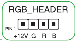
- AURA RGB headers
The RGB headers allow you to connect RGB LED strips.
![]()
The RGB headers support 5050 RGB multi-color LED strips (12V/G/R/B), with a maximum power rating of 3A (12V), and no longer than 3m.
![]()
![]()
Before you install or remove any component, ensure that the ATX power supply is switched off or the power cord is detached from the power supply. Failure to do so may cause severe damage to the motherboard, peripherals, or components.
![warning]() NOTE:
NOTE: - Actual lighting and color will vary with LED strip.
- If your LED strip does not light up, check if the RGB LED extension cable and the RGB LED strip are connected in the correct orientation, and the 12V connector is aligned with the 12V header on the motherboard.
- The LED strip will only light up when the system is powered on.
- The LED strip is purchased separately.
- Clear CMOS header
This header allows you to clear the CMOS RTC RAM data of the system setup information such as date, time, and system passwords.
To erase the RTC RAM:- Turn OFF the computer and unplug the power cord.
- Use a metal object such as a screwdriver to short the two pins.
- Plug the power cord and turn ON the computer.
- Hold down the <Del> key during the boot process and enter BIOS setup to reenter data.
![]()
![warning]() NOTE: If the steps above do not help, remove the onboard battery and short the two pins again to clear the CMOS RTC RAM data. After clearing the CMOS, reinstall the battery.
NOTE: If the steps above do not help, remove the onboard battery and short the two pins again to clear the CMOS RTC RAM data. After clearing the CMOS, reinstall the battery.
- COM Port header
This header is for a serial (COM) port. Connect the serial port module cable to this header, then install the module to a slot opening at the back of the system chassis.
![]()
- Front panel audio header
This header is for a chassis-mounted front panel audio I/O module that supports HD audio standard. Connect one end of the front panel audio I/O module cable to this header.
![]()
![]()
- We recommend that you connect a high-definition front panel audio module to this header to avail of the motherboard's high-definition audio capability.
- If you want to connect a high-definition front panel audio module to this header, set the Front Panel Type item in the BIOS setup to [HD Audio]. By default, this header is set to [HD Audio].
- S/PDIF Out header
This header is for an additional Sony/Philips Digital Interface (S/PDIF) port. Connect the S/PDIF Out module cable to this header, then install the module to a slot opening at the back of the system chassis.
![]()
- Speaker header
The 4-pin header is for the chassis-mounted system warning speaker. The speaker allows you to hear system beeps and warnings.
![]()
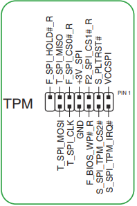
SPI TPM header
This header supports a Trusted Platform Module (TPM) system with a Serial Peripheral Interface (SPI), allowing you to securely store keys, digital certificates, passwords, and data. A TPM system also helps enhance network security, protects digital identities, and ensures platform integrity.
![]()
![warning]() NOTE: The SPI TPM module is purchased separately.
NOTE: The SPI TPM module is purchased separately.- 10-1 pin System Panel header
This header supports several chassis-mounted functions.- System power LED (2-pin +PWR_LED-)
This 2-pin header is for the system power LED. Connect the chassis power LED cable to this header. The system power LED lights up when you turn on the system power, and blinks when the system is in sleep mode. - Hard disk drive activity LED (2-pin +HDD_LED-)
This 2-pin header is for the HDD Activity LED. Connect the HDD Activity LED cable to this header. The HDD LED lights up or flashes when data is read from or written to the HDD.
![]()
- Power button/Soft-off button (2-pin PWR_BTN)
This header is for the system power button. - Reset button (2-pin RESET)
This 2-pin header is for the chassis-mounted reset button for system reboot without turning off the system power.
- System power LED (2-pin +PWR_LED-)


Rear panel connectors

- PS/2 Mouse port (green). This port is for a PS/2 mouse.
- Video Graphics Adapter (VGA) port. This 15-pin port is for a VGA monitor or other VGA-compatible devices.
- USB 3.2 Gen 1 (up to 5Gbps) ports. These 9-pin Universal Serial Bus (USB) ports connect to USB 3.2 Gen 1 devices.
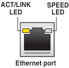
- Ethernet port. This port allows Gigabit connection to a Local Area Network (LAN) through a network hub. Refer to the table below for the Ethernet port LED indications.
Ethernet port LED indications
| Activity Link LED | Speed LED | ||
| Status | Description | Status | Description |
| OFF | No link | OFF | 10 Mbps connection |
| ORANGE | Linked | ORANGE | 100 Mbps connection |
| BLINKING | Data activity | GREEN | 1 Gbps connection |
- Line In port (light blue). This port connects the tape, CD, DVD player, or other audio sources.
- Line Out port (lime). This port connects a headphone or a speaker. In 4-channel, 5.1-channel, and 7.1-channel configurations, the function of this port becomes Front Speaker Out.
- PS/2 Keyboard port (purple). This port is for a PS/2 keyboard.
- HDMI™ port. This port is for a High-Definition Multimedia Interface (HDMI™) connector, and is HDCP compliant allowing playback of HD DVD, Blu-ray, and other protected content.
- DisplayPort. This port is for a Display Port-compatible device.
- USB 2.0 ports. These 4-pin Universal Serial Bus (USB) ports are for USB 2.0 devices.
- Intel® Wi-Fi 5 9462NGW ports. These ports connect to a Wi-Fi antenna.
![warning]() NOTE:
NOTE: - Ensure that the ASUS 1x1 dual band Wi-Fi antenna is securely installed to the Wi-Fi ports.
- Ensure that the antenna is at least 20 cm away from all persons.
- Microphone port (pink). This port connects a microphone.
![warning]() NOTE:
NOTE:
Refer to the audio configuration table for the function of the audio ports in 2, 4, 5.1, or 7.1-channel configuration.
Audio 2, 4, 5.1 or 7.1-channel configuration
| Port | Headset 2-channel | 4-channel | 5.1-channel | 7.1-channel |
| Light Blue (Rear panel) | Line In | Rear Speaker Out | Rear Speaker Out | Rear Speaker Out |
| Lime (Rear panel) | Line Out | Front Speaker Out | Front Speaker Out | Front Speaker Out |
| Pink (Rear panel) | Mic In | Mic In | Bass/Center | Bass/Center |
| Lime (Front panel) | — | — | — | Side Speaker Out*/ Headphone |
| Pink (Front panel) | — | — | — | Mic In* / Side Speaker Out |
* Multi-streaming is disabled by default, and the Lime (front panel) jack may be used as Side Speaker Out. If multi-streaming is enabled, the Lime (front panel) jack will support headphone, and the Pink (front panel) jack will support Side Speaker Out.
NOTE: To configure a 7.1-channel audio output:
Use a chassis with HD audio module in the front panel to support a 7.1-channel audio output.
Central Processing Unit (CPU)
This motherboard comes with a LGA1200 socket designed for 11 th Gen Intel ® Core™ Processors & 10 th Gen Intel ® Core TM, Pentium ® Gold and Celeron ® Processors.
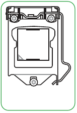
Unplug all power cables before installing the CPU.
NOTE:
- Ensure that you install the correct CPU designed for the LGA1200 socket only. DO NOT install a CPU designed for LGA1150, LGA1151, LGA1155 and LGA1156 sockets on the LGA1200 socket.
- Upon purchase of the motherboard, ensure that the PnP cap is on the socket and the socket contacts are not bent. Contact your retailer immediately if the PnP cap is missing, or if you see any damage to the PnP cap/socket contacts/motherboard components.
- Keep the cap after installing the motherboard. ASUS will process Return Merchandise Authorization (RMA) requests only if the motherboard comes with the cap on the LGA1200 socket.
- The product warranty does not cover damage to the socket contacts resulting from incorrect CPU installation/removal, or misplacement/loss/incorrect removal of the PnP cap.
Installing the CPU

NOTE:
Apply the Thermal Interface Material to the CPU heatsink and CPU before you install the heatsink and fan if necessary.
System memory
This motherboard comes with two Double Data Rate 4 (DDR4) Dual Inline Memory Module (DIMM) sockets. The figure illustrates the location of the DDR4 DIMM sockets:

| Channel | Sockets |
| Channel A | DIMM_A1* |
| Channel B | DIMM_B1* |
- You may install varying memory sizes in Channel A and Channel B. The system maps the total size of the lower-sized channel for the dual-channel configuration. Any excess memory from the higher-sized channel is then mapped for single-channel operation.
- Always install DIMMs with the same CAS latency. For optimal compatibility, we recommend that you install memory modules of the same version or date code (D/C) from the same vendor. Check with the retailer to get the correct memory modules.
- A DDR4 memory module is notched differently from a DDR, DDR2, or DDR3 module. DO NOT install a DDR, DDR2, or DDR3 memory module to the DDR4 slot.
NOTE:
- The default memory operation frequency is dependent on its Serial Presence Detect (SPD), which is the standard way of accessing information from a memory module. Under the default state, some memory modules for overclocking may operate at a lower frequency than the vendor-marked value.
- For system stability, use a more efficient memory cooling system to support a full memory load.
- Refer to www.asus.com for the latest Memory QVL (Qualified Vendors Lists),and memory frequency support depends on the CPU types.
Recommended memory configurations

Installing a DIMM

M.2 Installation

NOTE:
- Ensure to install the bundled M.2 rubber pad before installing your single sided M.2 storage device.
- DO NOT install the bundled M.2 rubber pads when installing a double-sided M.2 storage device. The rubber pad installed by default is compatible with double sided M.2 storage devices.
- The diagrams in this section are for reference only.
- The M.2 device is purchased separately.
BIOS Information
Knowing BIOS
NOTE: The new ASUS UEFI BIOS is a Unified Extensible Interface that complies with UEFI architecture, offering a user-friendly interface that goes beyond the traditional keyboard only BIOS controls to enable a more flexible and convenient mouse input. You can easily navigate the new UEFI BIOS with the same smoothness as your operating system. The term "BIOS" in this user manual refers to "UEFI BIOS" unless otherwise specified.
BIOS (Basic Input and Output System) stores system hardware settings such as storage device configuration, overclocking settings, advanced power management, and boot device configuration that are needed for system startup in the motherboard CMOS. In normal circumstances, the default BIOS settings apply to most conditions to ensure optimal performance. DO NOT change the default BIOS settings except in the following circumstances:
- An error message appears on the screen during the system bootup and requests you to run the BIOS Setup.
- You have installed a new system component that requires further BIOS settings or update.
Inappropriate BIOS settings may result to instability or boot failure. We strongly recommend that you change the BIOS settings only with the help of a trained service personnel.
NOTE: BIOS settings and options may vary due to different BIOS release versions. Please refer to the latest BIOS version for settings and options.
For more information on BIOS configurations, please refer to https://www.asus.com/support, or download the BIOS manual by scanning the QR code.

BIOS Setup program
Use the BIOS Setup to update the BIOS or configure its parameters. The BIOS screens include navigation keys and brief onscreen help to guide you in using the BIOS Setup program.
Entering BIOS at startup
To enter BIOS Setup at startup, press <Delete> or <F2> during the Power-On Self Test (POST). If you do not press <Delete> or <F2>, POST continues with its routines.
Entering BIOS Setup after POST
To enter BIOS Setup after POST:
- Press <Ctrl>+<Alt>+<Delete> simultaneously.
- Press the reset button on the system chassis.
- Press the power button to turn the system off then back on. Do this option only if you failed to enter BIOS Setup using the first two options.
After doing either of the three options, press <Delete> key to enter BIOS.
- Ensure that a USB mouse is connected to your motherboard if you want to use the mouse to control the BIOS setup program.
- If the system becomes unstable after changing any BIOS setting, load the default settings to ensure system compatibility and stability. Select the Load Optimized Defaults item under the Exit menu or press hotkey <F5>.
- If the system fails to boot after changing any BIOS setting, try to clear the CMOS and reset the motherboard to the default value.
- The BIOS setup program does not support Bluetooth devices.
BIOS menu screen
The BIOS Setup program can be used under two modes: EZ Mode and Advanced Mode. You can change modes from Setup Mode in Boot menu or by pressing the <F7> hotkey.
ASUS EZ Flash 3
The ASUS EZ Flash 3 feature allows you to update the BIOS without using an OS-based utility.
Ensure to load the BIOS default settings to ensure system compatibility and stability. Select the Load Optimized Defaults item under the Exit menu or press hotkey <F5>.
To update the BIOS:
- This function can support devices such as a USB flash disk with FAT 32/16 format and single partition only.
- DO NOT shut down or reset the system while updating the BIOS to prevent system boot failure!
- Insert the USB flash disk that contains the latest BIOS file to the USB port.
- Enter the Advanced Mode of the BIOS setup program. Go to the Tool menu to select ASUS EZ Flash 3 Utility and press <Enter>.
- Press the Left/Right arrow keys to switch to the Drive field.
- Press the Up/Down arrow keys to find the USB flash disk that contains the latest BIOS, and then press <Enter>.
- Press the Left/Right arrow keys to switch to the Folder field.
- Press the Up/Down arrow keys to find the BIOS file, and then press <Enter> to perform the BIOS update process. Reboot the system when the update process is done.
ASUS CrashFree BIOS 3
The ASUS CrashFree BIOS 3 utility is an auto recovery tool that allows you to restore the BIOS file when it fails or gets corrupted during the updating process. You can restore a corrupted BIOS file using a USB flash drive that contains the BIOS file.
Recovering the BIOS
- Download the latest BIOS version for this motherboard from https://www.asus.com/support/.
- Rename the BIOS file as ASUS.CAP or PH510MAW.CAP and copy the renamed BIOS file to a USB flash drive.
- Turn on the system.
- Insert the USB flash drive containing the BIOS file to a USB port.
- The utility automatically checks the devices for the BIOS file. When found, the utility reads the BIOS file and enters ASUS EZ Flash 3 automatically.
- The system requires you to enter BIOS Setup to recover the BIOS setting. To ensure system compatibility and stability, we recommend that you press <F5> to load default BIOS values.
DO NOT shut down or reset the system while updating the BIOS! Doing so can cause system boot failure!
Intel® 9462NGW output power table:
| Function | Frequency | Maximum Output Power (EIRP) |
| WiFi | 2412 - 2472 MHz | 17.74 dBm |
| 5150 - 5350 MHz | 19.38 dBm | |
| 5470 - 5725 MHz | 20.10 dBm | |
| 5725 - 5850 MHz | 11.18 dBm | |
| Bluetooth | 2402 - 2480 MHz | 11.94 dBm |
Contact information & Technical Support
ASUSTeK COMPUTER INC.
Telephone +886-2-2894-3447
Fax +886-2-2890-7798
Web site https://www.asus.com
Technical Support
Telephone +86-21-38429911
Online support https://qr.asus.com/techserv
ASUS COMPUTER INTERNATIONAL (America)
Telephone +1-510-739-3777
Fax +1-510-608-4555
Web site https://www.asus.com/us/
Technical Support
Support fax +1-812-284-0883
Telephone +1-812-282-2787
Online support https://qr.asus.com/techserv
Warranty
For all the guarantee information, please visit https://www.asus.com/support.
Safety information
Electrical safety
- To prevent electrical shock hazard, disconnect the power cable from the electrical outlet before relocating the system.
- When adding or removing devices to or from the system, ensure that the power cables for the devices are unplugged before the signal cables are connected. If possible, disconnect all power cables from the existing system before you add a device.
- Before connecting or removing signal cables from the motherboard, ensure that all power cables are unplugged.
- Seek professional assistance before using an adapter or extension cord. These devices could interrupt the grounding circuit.
- Ensure that your power supply is set to the correct voltage in your area. If you are not sure about the voltage of the electrical outlet you are using, contact your local power company.
- If the power supply is broken, do not try to fix it by yourself. Contact a qualified service technician or your retailer.
Operation safety
- Before installing the motherboard and adding components, carefully read all the manuals that came with the package.
- Before using the product, ensure all cables are correctly connected and the power cables are not damaged. If you detect any damage, contact your dealer immediately.
- To avoid short circuits, keep paper clips, screws, and staples away from connectors, slots, sockets and circuitry.
- Avoid dust, humidity, and temperature extremes. Do not place the product in any area where it may be exposed to moisture.
- Place the product on a stable surface.
- If you encounter technical problems with the product, contact a qualified service technician or your retailer.
- Your motherboard should only be used in environments with ambient temperatures between 0°C and 40°C
Documents / Resources
References
Download manual
Here you can download full pdf version of manual, it may contain additional safety instructions, warranty information, FCC rules, etc.
Advertisement


Need help?
Do you have a question about the PRIME H510M-A and is the answer not in the manual?
Questions and answers