Advertisement
Quick Links
BEFORE YOU START
WHAT'S INCLUDED - BOX CONTENTS
BOX 1 CONTENTS
BOX 1 INCLUDED HARDWARE
BOX 2 CONTENTS
BOX 2 INCLUDED HARDWARE
USING THE L-SHAPED HANDLE BOLT LOCKING
MECHANISM
DISENGAGING THE LOCKING MECHANISM
ENGAGING THE LOCKING MECHANISM
ASSEMBLING THE COCKPIT FRAME
1: ASSEMBLING THE LEFT SIDE OF THE MAIN FRAME
2: ASSEMBLING THE RIGHT SIDE OF THE MAIN FRAME
3A: INSERTING UPPER AND LOWER CONNECTING
TUBES
3B: ADDING THE LEFT SIDE OF THE FRAME
4: ATTACHING THE CONNECTING PANEL
5: ATTACHING THE TOP PANEL
6: ATTACHING THE RUBBER FEET
INSTALLING THE PEDAL AND STEERING
ASSEMBLIES
7: PREPARING THE FRAME AND THE PEDAL
MOUNTING ASSEMBLY
8A: PLACING THE PEDAL MOUNTING ASSEMBLY
8B: SECURING THE PEDAL MOUNTING ASSEMBLY
8C: ADDING THE L-BOLTS TO THE PEDAL MOUNTING
ASSEMBLY
9: ATTACHING THE FRONT PANEL
10A: ASSEMBLING THE STEERING MOUNT
10B: ASSEMBLING THE DIRECT DRIVE UNDER MOUNT
INSTALLING THE ONBOARD MONITOR MOUNT
11A: ATTACHING THE ONBOARD MONITOR MOUNT
BASE
11B: ATTACHING THE ONBOARD MONITOR MOUNT
11C: INSTALLING THE ONBOARD MONITOR
OPTIONAL: INSTALLING THE TWO-PIECE
BUCKET SEAT
ASSEMBLING THE OPTIONAL TWO-PIECE BUCKET
SEAT
INSTALLING THE SEAT BRACKETS
INSTALLING THE SEAT SLIDE ASSEMBLY
INSTALLING THE OPTIONAL TWO-PIECE BUCKET SEAT
OPTIONAL: INSTALLING THE SHIFTER
MOUNTING KIT
ATTACHING THE SHIFTER MOUNT TUBE (LEFT OR
RIGHT)
INSTALLING THE CAM LEVER CLAMPS
INSTALLING THE SHIFTER AND HANDBRAKE
MOUNTING PLATES
OPTIONAL: INSTALLING THE KEYBOARD TRAY
ASSEMBLY
1: ATTACHING THE CLAMPING BLOCKS
2: ATTACHING THE ARTICULATING ARM
3: ATTACHING THE KEYBOARD TRAY
OPTIONAL: INSTALLING THE FRONT MOUNT
BRACKET ASSEMBLY
OPTIONAL: INSTALLING THE LEFT AND RIGHT
UPPER ACCESSORY MOUNTS
OPTIONAL: INSTALLING THE ACCESSORY PC
TRAY
ADJUSTING THE PC TRAY WIDTH
OPTIONAL: INSTALLING THE INVERTED PEDAL
BRACKETS
OPTIONAL: INSTALLING THIRD-PARTY
ACCESSORIES
ADDING THE T-NUTS TO THE ACCESSORY RAILS
INSTALLING THIRD-PARTY ACCESSORIES
SETUP AND ADJUSTMENT SUGGESTIONS
PEDAL MOUNT ASSEMBLY SUGGESTED ADJUSTMENT
FORMULA STYLE PEDAL MOUNT ASSEMBLY
SUGGESTED ADJUSTMENT
POSITIONING SEPARATE THIRD-PARTY PEDALS ON
THE PEDAL MOUNTING PLATE
SUGGESTED SEAT / PEDAL ADJUSTMENT FOR
MULTIPLE DRIVING POSITIONS
STICKER POSITIONS
CARE AND MAINTENANCE
WARRANTY
LEGAL
MANUAL | QUICK START GUIDE
FANATEC CLUBSPORT GT
RACING SIMULATOR COCKPIT
BEFORE YOU START
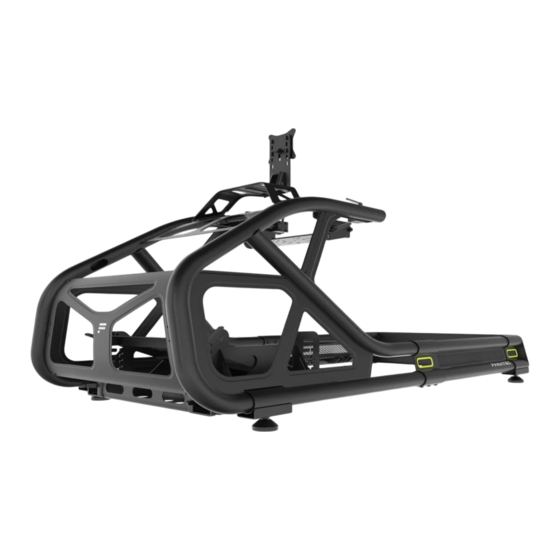
Congratulations on purchasing your new Fanatec ClubSport GT cockpit.
Please take a moment to carefully read this guide prior to assembling.
CAUTION: Your cockpit is engineered from steel for strength and durability.
Some of the components are heavy. Please excersise caution when handling these parts.
Ensure the chosen build area is clutter free and there is sufficient space for assembly.
Use a soft floor covering such as an old blanket or rug to protect both the finish of your Fanatec
ClubSport GT cockpit and your floor during assembly.
To avoid stripping bolt threads, do not overtighten.
At the end of this guide, you will also find setup tips, suggestions for various driving positions, and
peripheral mounting.
WHAT'S INCLUDED - BOX CONTENTS
BOX 1 CONTENTS
Left Side Front Frame Assembly
Right Side Front Frame Assembly
Right Side Rear Frame Assembly
Connecting Brackets
(Left and Right are identical)
Lower Front Connecting Tube
Upper Front Connecting Tube
(Long)
(Short)
Top Panel
BOX 1 INCLUDED HARDWARE
Tool Kit Bag:
Spare Parts Bag:
• M5 Allen Key (1x)
• M5 16mm Bolts (2x)
• M6 Allen Key (1x)
• M5 Spring Washers (2x)
• M8 Allen Key (1x)
• M5 Washers (2x)
• M8 Open-ended Wrench (1x)
• M6 12mm Bolts (2x)
• M12 Open-ended Wrench (1x)
• M6 Curved Washers (2x)
• M6 Shoulder Bolt (1x)
• M8 16mm Bolts (2x)
• M8 20mm Bolts (2x)
• M8 35mm Bolts (2x)
• M8 Curved Washers (2x)
• M8 Washers (2x)
• R-pin (1x)
Sticker & Velcro Bag:
Step 1 Bag:
• Four-color Arrow Labels (4x)
• M8 20mm Bolts (6x)
• Velcro, White (4x)
• M8 Curved Washers (6x)
Step 3A Bag:
Step 3B Bag:
• M8 35mm Bolts (2x)
• M8 35mm Bolts (2x)
Step 5 Bag:
Step 6 Bag:
• M6 12mm Bolts (8x)
• M12 Rubber Feet (4x)
• M6 15mm L-Bolts (8x)
BOX 2 CONTENTS
Pedal Mounting Assembly (pre-
Onboard Monitor Mount Upright
assembled)
VESA Mount 100mm x 100mm
Right Steering Mount Bracket
Main Wheelbase Mounting Plate
Seat Slider Adjustment Handle
Right Side Seat Mounting Bracket
BOX 2 INCLUDED HARDWARE
Step 8C Bag:
Step 9 Bag:
• M6 15mm L-Bolts (2x)
• M6 12mm Bolts (6x)
Step 10B Bag:
Step 11A Bag:
• M6 Shoulder Bolts (2x)
• M8 16mm Bolts (4x)
• M8 20mm L-Bolts (2x)
• M8 Spring Washers (2x)
• M8 Washers (4x)
• Locking Pin (1x)
Step 11C Bag:
Seat Assembly Bag:
• M4 12mm Screws (4x)
• M8 15mm Bolts (4x)
• M4 15mm Spacer Screws (4x)
• M8 20mm Bolts (4x)
• M4 30mm Spacer Screws (4x)
• M8 Allen Key (1x)
• M4 40mm Spacer Screws (4x)
• M4 Allen Key (1x)
Seat Step 1B Bag:
Seat Step 1C Bag:
• R-pins (2x)
• M8 20mm Bolts (4x)
• M8 Spring Washers (4x)
• M8 Washers (4x)
USING THE L-SHAPED HANDLE BOLT LOCKING MECHANISM
DISENGAGING THE LOCKING MECHANISM
Pull the handle outward to disengage the lock, allowing it to rotate freely in either direction.
ENGAGING THE LOCKING MECHANISM
Release the handle in the desired position to re-engage the lock. Rotate it counterclockwise to loosen or clockwise to
tighten the threaded bolt.
ASSEMBLING THE COCKPIT FRAME
NOTE: We recommend that you do not fully tighten the bolts until step 5 is completed.
Begin the assembly of your Fanatec ClubSport GT cockpit frame by unpacking the components from Box 1.
Follow the steps for assembly of the cockpit frame laid out in this section.
1: ASSEMBLING THE LEFT SIDE OF THE MAIN FRAME
Open the tool and hardware bags labeled STEP 1 and HARDWARE KIT.
To complete the step, the following hardware and tools will be used:
M8 Allen Key
M8 20mm Bolts (6x)
1. Slide the Left Side Front Frame Assembly (1) and Left Side Rear Frame Assembly (3) into the Connecting Bracket (5).
2. Ensure the mounting holes on all three pieces (1, 3, 5) are aligned.
3. Screw six M8 20mm Bolts (B7) and Curved Washers (W7) into the mounting holes to connect the sections of the
main frame together. The concave side of the curved washer must face the frame.
TIP: First screw in the three M8 20mm Bolts on the bottom of the connecting bracket (5).
2: ASSEMBLING THE RIGHT SIDE OF THE MAIN FRAME
Open the hardware bag labeled STEP 2.
To complete the step, the following hardware and tools will be used:
M8 Allen Key
M8 20mm Bolts (6x)
1. Slide the Right Side Front Frame Assembly (2) and Right Side Rear Frame Assembly (4) into the Connecting Bracket
(5).
2. Ensure the mounting holes on all three pieces (2, 4, 5) are aligned.
3. Screw six M8 20mm Bolts (B7) and Curved Washers (W7) into the mounting holes to connect the sections of the
main frame together. The concave side of the curved washer must face the frame.
Left Side Rear Frame Assembly
Rear Connecting Plate
Front Panel
Sticker & Velcro Bag:
• Four-color Arrow Labels (4x)
• Velcro, Black (4x)
Step 2 Bag:
• M8 20mm Bolts (6x)
• M8 Curved Washers (6x)
Step 4 Bag:
• M6 12mm Bolts (8x)
• M6 Curved Washers (8x)
Onboard Monitor Mount Base
Left Steering Mount Bracket
Left Side Seat Mounting Bracket
Step 10A Bag:
• M5 16mm Bolts (8x)
• M5 Spring Washers (8x)
• M5 Washers (8x)
Step 11B Bag:
• M8 20mm Bolts (2x)
• M8 Nuts (2x)
• M8 T-Bolt (1x)
• M8 Washer (1x)
Seat Step 1A Bag:
• M8 40mm Plastic Washers (4x)
• M8 25mm L-Bolts (4x)
• M8 Washers (4x)
M8 Curved Washers (6x)
M8 Curved Washers (6x)
Advertisement

Related Manuals for FANATEC CLUBSPORT GT


Summary of Contents for FANATEC CLUBSPORT GT
- Page 1 Ensure the chosen build area is clutter free and there is sufficient space for assembly. OPTIONAL: INSTALLING THE SHIFTER Use a soft floor covering such as an old blanket or rug to protect both the finish of your Fanatec MOUNTING KIT ClubSport GT cockpit and your floor during assembly.
- Page 2 Avoid using excessive force to prevent stripping the threads. INSTALLING THE PEDAL AND STEERING ASSEMBLIES Continue with the assembly of your Fanatec ClubSport GT cockpit by unpacking the components from Box 2. 7: PREPARING THE FRAME AND THE PEDAL MOUNTING ASSEMBLY...
- Page 3 NOTE: Check the smoothness of the sliding rods and radial bearing blocks by gently sliding the Pedal Mounting Assembly back and forth. IF THE PEDAL MOUNTING ASSEMBLY DOESN'T SLIDE SMOOTHLY ... 1. Loosen the L-shaped bolts clamping the radial bearing blocks to the steel sliding rods. 2.
- Page 4 M4 Allen Key M4 12mm Bolts (4x) M4 15mm Spacer Screws (4x) M4 30mm Spacer Screws (4x) M4 40mm Spacer Screws (4x) 1. For recessed VESA mounts, use the appropriate included spacer screws (S1, S2, S3) and screw them into your monitor first.
- Page 5 INSTALLING THE SHIFTER AND HANDBRAKE MOUNTING PLATES Open the hardware bag labeled SHIFTER (PLATE). To complete the step, the following hardware and tools will be used: M6 Allen Key M6 12mm Countersunk Bolts (11x) Shifter Mounting Plate 1. Place the larger Shifter Mounting Plate over the clamping blocks. 2.
- Page 6 M6 T-Nuts (4x) 1/4 Inch 20 T-Nuts (4x) You can add third-party accessories such as Elgato products and streaming equipment to your Fanatec ClubSport GT racing cockpit. Additional third-party mounting hardware may be used with M6 and 1/4 inch threaded T-Nuts (N2).
-
Page 7: Care And Maintenance
Use different colored labels for multiple drivers. CARE AND MAINTENANCE Your Fanatec Clubsport GT cockpit is manufactured to be robust and sturdy during use. However, by following basic care and maintenance steps, you can improve the longevity and performance of your cockpit.
Need help?
Do you have a question about the CLUBSPORT GT and is the answer not in the manual?
Questions and answers