Noritz EZ111DV Installation Manual
Condensing tankless gas water heater
Hide thumbs
Also See for EZ111DV:
- Installation manual (90 pages) ,
- Owner's manual (32 pages) ,
- Owner's manual (24 pages)
Table of Contents
Advertisement
Quick Links
CONDENSING TANKLESS GAS WATER HEATER
Installation Manual
Models : EZ111DV (GQ-C3261WX-FF US)
EZ98DV (GQ-C2861WX-FF US)
EZ71DV (GQ-C2661WX-FF US)
DANGER
Installing Water Heaters with Propane (LP) Gas
THIS WATER HEATER IS EQUIPPED FOR NATURAL GAS.
This water heater is equipped with orifices for the
natural gas.
Orifice necessary for Propane (LP) conversion is
provided with the water heater. For conversion to
Propane (LP) gas, follow the instruction guide in the
conversion kit, replace the parts correctly.
WARNING
If the information in this manual is not followed
exactly, a fire or explosion can result causing
property damage, personal injury, or loss of life.
• Do not store or use gasoline or other flammable
vapors and liquids in the vicinity of this or any
other appliance.
• WHAT TO DO IF YOU SMELL GAS
- Do not try to light any appliance.
- Do not touch any electrical switch; do not use
any phone in your building.
- Immediately call your gas supplier from a
neighbor's phone. Follow the gas supplier's
instructions.
- If you cannot reach your gas supplier, call the
fire department.
• Installation and service must be performed by
a qualified installer, service agency or the gas
supplier.
FOR USE IN RESIDENTIAL OR MANUFACTURED HOME APPLICATIONS.
Installation must conform with local codes, or in the absence of local codes, the National Fuel Gas Code, ANSI Z223.1 / NFPA
54 (latest edition) and/or the Natural Gas and Propane Installation Code CSA B149.1 (latest edition).
When applicable, installation must conform with the Manufactured Home Construction and Safety Standard, Title 24 CFR,
Part 3280 or the Canadian Standard CAN/CSA-Z240 MH Mobile Homes, Series M86.
Noritz America reserves the right to discontinue, or change at any time, the designs and/or specifications of its products
without notice.
Contact Noritz America at 1-866-766-7489 if you have any questions or concerns.
NORITZ America Corporation
CAUTION
Requests to installers
• In order to use the water heater safely, read
this installation manual carefully and follow the
installation instructions.
• Failures and damage caused by erroneous work
or work not performed as instructed in this
manual are not covered by the Noritz America
Limited Warranty.
• The remote controller is sold separately.
When using RC-9018M, refer to the installation
manual provided with the remote controller.
• Confirm that the installation was done properly
in accordance with this installation manual upon
completion.
• After completing installation, either place this
installation manual and owner's guide (with
warranty registration information included) in
a plastic pouch and attach it to the side of the
water heater (or the inside of the pipe cover
or recess box if applicable) or hand it to the
customer to retain for future reference. For the
warranty conditions and limitations, see the
owner's guide.
SBB81HE
Rev. 04/24
Low NOx Approved by SCAQMD
14 ng/J or 20 ppm
(Natural Gas Only)
Advertisement
Table of Contents

Related Manuals for Noritz EZ111DV


Summary of Contents for Noritz EZ111DV
- Page 1 When applicable, installation must conform with the Manufactured Home Construction and Safety Standard, Title 24 CFR, Part 3280 or the Canadian Standard CAN/CSA-Z240 MH Mobile Homes, Series M86. Noritz America reserves the right to discontinue, or change at any time, the designs and/or specifications of its products without notice.
-
Page 2: Table Of Contents
Contents Connecting the Water Supply 8.1 Installation ........41 8.2 Water Treatment ......43 Before Installation Connecting the Condensate Drain 44 About the Water Heater 10 Connecting Electricity 2.1 Included Accessories ....... 5 10.1 Water Heater ........46 2.2 Optional Accessories ....... 5 10.2 Remote Controller ...... -
Page 3: Before Installation
DANGER for 199,900 Btu/h, 180,000 Btu/h or 160,000 Btu/h. Indicates an imminently hazardous situation that, 199,900 Btu/h: EZ111DV (GQ-C3261WX-FF US) if not avoided, will result in death or serious injury. 180,000 Btu/h: EZ98DV (GQ-C2861WX-FF US) 160,000 Btu/h: EZ71DV (GQ-C2661WX-FF US) - Page 4 terminal for the horizontally vented gas fueled CAUTION heating appliance or equipment. The sign shall read, in print size no less than one-half (1/2) in. in Do not use for purposes other than those size, “GAS VENT DIRECTLY BELOW. KEEP CLEAR OF specified ALL OBSTRUCTIONS”.
-
Page 5: About The Water Heater
2 About the Water Isolation Valves (includes pressure relief valve) Heater [IK-WV-200-X] Isolation valves are necessary for flushing the heat exchanger. They allow for easy flushing and troubleshooting of the 2.1 Included Accessories system. PVC Concentric Termination 2 in. (50 mm) : [PVC-2CT] 3 in. - Page 6 40°F Canada. (5°C). After installation, site ambient temperature must be greater than -4°F (-20°C). Flex vent pipe breakage may occur if these temperature requirements are not observed. Noritz Connect Wireless Adapter NWC-ADAPTER Remote Controller (See page 58) [NAW-1 US] [RC-7651M-A]...
-
Page 7: Specifications
2.3 Specifications • Specifications may be changed without prior notice. • The capacity may differ slightly depending on the water pressure, piping conditions, and water temperature. Item Specification Model Name EZ111DV EZ98DV EZ71DV (GQ-C3261WX-FF US) (GQ-C2861WX-FF US) (GQ-C2661WX-FF US) Installation... -
Page 8: Dimensions
2.4 Dimensions INCLUDED ACCESSORIES (FOR MOUNTING THE WATER HEATER) 0.4 [9] 11.8 [300] 3.5 [88] 7×Ø0.2 [6] 3×0.5 [12]×1.6 [40] RECTANGLE HOLE 16.0 [406] 10.2 [260] 10.2 [260] 5.1 [130] 5.5 [140] 1.1 [28] 0.4 [10] 2.1 [52] 3.9 [100] 5.2 [132] 6.7 [169] 8.1 [206]... - Page 9 < inch[mm] > 18.0 [458] 13.7 [349] 2.6 [65] HOT WATER OUTLET (3/4 ) WATER DRAIN VALVE WATER DRAIN VALVE (WATER FILTER) COLD WATER INLET (3/4 ) 18.1 [461] 5.1 [130] 9.9 [251] I.DΦ2.4 [61] I.DΦ2.4 [61] FLUE COLLAR AIR INLET (VIEW FROM BOTTOM) WIRING THROUGHWAY (AC120V)
-
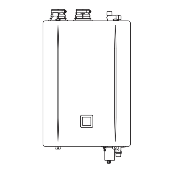
Page 10: External View
2.5 External View The exterior view of air intake side (“Intake Pipe”) may be different due to the installed item. (Example of non-direct vent installation) Indoor Installation Flex Vent 2 in. Conversion Kit (EZ2-CK-1) (Example of direct vent installation) Water Supply Valve Hot Water Valve Intake Pipe Water Drain... -
Page 11: Choosing An Installation Location
3 Choosing an CAUTION Installation Do not install in the following places • Locations with obstructions or stagnant air. Location • Near staircases or emergency exits. • Locations where items may fall on the water heater. • On common walls between apartments, as the appliance will make some operational noises while it is running. - Page 12 Perform suggested treatment and maintenance measures according to “8.2 Water Treatment”. Damage to the water heater as a result of the following is not covered by the Noritz America Limited Warranty. - Water with a hardness exceeding 12 gpg (200 mg/L)
-
Page 13: Installation Clearances
4 Installation Space for Inspection/Repair Clearances The following minimum clearances should be met to provide enough space for inspection and repair. WARNING Exhaust Install in accordance with relevant building and mechanical codes, as well as any local, state, or national regulations, or in the absence of local and state codes, refer to National Fuel Gas Code ANSI Z223.1 / NFPA 54 (latest edition). -
Page 14: Outdoor Installation
4.2 Outdoor Installation 4.3 For Quick Connect Multi-System Required Clearances from the Water The quick connect cord is 6 ft (1.8 m) long. Install the water heaters 3-18 in. (76-457 mm) apart Heater from each other to ensure the cord will be able to reach between the water heaters. -
Page 15: Mounting The Water Heater To The Wall
• Install the appliance on a vertical wall and (Not supplied ensure that it is level. from Noritz.) 3. Affix the mounting bracket (lower) to the wall by 2 screws. 1. Ensure that the wall mounting bracket is level. -
Page 16: Adjusting For Elevations Above
6 Venting the 5.2 Adjusting for Elevations Above 1,000 Water Heater • Change the settings according to altitude, if this water heater is installed at an altitude of 1,000 ft (305 m) or higher. For how to configure the WARNING settings, see page 53 when using the app, and see page 55 when using the buttons on the Carbon monoxide poisoning... -
Page 17: General Requirements
6.2 General Requirements - DuraVent PolyPro® / FasNSeal® Parts # Single Wall 2PPS-xxBL/3PPS-xxBL, Pipe 2PPS-xxL/3PPS-xxL, (2 in. / 3 in.) FSVLxx03, FSAVL3(-2) 6.2.1 Vent Piping Material 2PPS-E90(B)L/3PPS-E90(B)L, Elbow 2PPS-E45(B)L/3PPS-E45(B)L, FSELB9003/8803/4503/1503 • This is a Category IV appliance. 2PPS-E90(B)L/3PPS-E90(B)L, Only vent materials approved for use with 2PPS-T(B)L/3PPS-T(B)L, Termination** Category IV appliances may be used. -
Page 18: Installation Instructions
For 2 in. flexible polypropylene material - Centrotherm - lnnoFlue® polypropylene Chimney Kit (3 in.): IFCK03xx, • Flex vent 2 in. conversion kit (EZ2-CK-1) must be Exhaust Flexible Pipe Polypropylene (3 in.): used when using 2 in. flexible polypropylene pipe IFVL03xxx for vent pipe installation. - Page 19 For PVC/CPVC/polypropylene material For flexible chimney pipe • When preparing and assembling the pipe, • Every venting system must be properly planned follow instructions as provided by the pipe and installed for optimum performance and manufacturer. In general, the following practices safety.
-
Page 20: Vent Length
65 ft (20 m). NOTE Below are additional models Both maximum lengths are reduced by the approved for use by Noritz and number of elbows used, as shown in the following supplied by IPEX. Refer to the IPEX... - Page 21 Vent length configurations Step 2: Straight pipe length Maximum equivalent (Vertical length + horizontal length) vent length* Short or Equivalent length of 17 ft V (Vertical) Long components Step 3: H (Horizontal) Number of elbows Short Flexible pipe: 1 ft (0.3 m) <...
-
Page 22: Selecting A Vent Type
• Example 2: Long 6.3 Selecting a Vent Type - Vent size: 3 in. - V (Vertical length): 30 ft - H (Horizontal length): 10 ft Direct Vent - 87° elbow: 3 1 ft × 30 + 1 ft × 10 + 5 ft × 3 = 55 ft 50 ft < Total equivalent length ≤ 75 ft •... - Page 23 Common Vent This water heater is suitable for a common vent system. To make a common vent system, contact Noritz America at 1-866-766-7489 or scan the following two-dimensional barcode and then refer to the common vent installation manual for detailed information.
-
Page 24: Vent Pipe Installation (Direct Vent)
6.4 Vent Pipe Installation (Direct Vent) 6.4.1 Clearance Requirements from Vent Terminations to Building Openings (When supplying combustion air from the outdoors) • All clearance requirements are in accordance with ANSI Z21.10.3 and the National Fuel Gas Code, ANSI Z223.1 and in Canada, in accordance with the Natural Gas and Propane Installation Code CSA B149.1. [ D ] Vent Terminal Ven lated soffit... - Page 25 6.4.2 Horizontal Vent Termination For horizontal vent termination - PVC, CPVC, polypropylene or stainless steel material • Use a condensation drain if necessary. • In the Commonwealth of Massachusetts, a carbon monoxide detector is required for all side wall horizontally vented gas fuel equipment.
- Page 26 Alternate horizontal vent termination - PVC, CPVC, polypropylene or stainless steel material (When 3 ft (0.9 m) distance between intake and exhaust cannot be ensured.) WARNING • If the distance between the air intake and exhaust vent terminations is too short, the water heater will draw in the exhaust gases through the intake.
- Page 27 For horizontal PVC concentric termination - PVC/CPVC/polypropylene material only • The concentric termination may be shortened, but not lengthened from the length when supplied from the factory. • 2 in. (50 mm) or 3 in. (75 mm) PVC, CPVC or polypropylene pipe may be used with the concentric termination.
-
Page 28: Vertical Vent Termination
6.4.3 Vertical Vent Termination For vertical vent termination - PVC, CPVC, polypropylene or stainless steel material About the termination • Intake and exhaust terminations must use the same type of elbow (i.e. both 90° elbows). This will help with proper combustion by putting both terminations in the same pressure zone. •... - Page 29 For vertical PVC concentric termination - PVC/CPVC/polypropylene material only • The concentric termination may be shortened, but not lengthened from the length when supplied from the factory. • 2 in. (50 mm) or 3 in. (75 mm) PVC, CPVC or polypropylene pipe may be used with the concentric termination.
-
Page 30: Vent Pipe Installation (Non-Direct Vent)
6.5 Vent Pipe Installation (Non-Direct Vent) 6.5.1 Clearance Requirements from Vent Terminations to Building Openings (Other than Direct Vent) • All clearance requirements are in accordance with ANSI Z21.10.3 and the National Fuel Gas Code, ANSI Z223.1 and in Canada, in accordance with the Natural Gas and Propane Installation Code CSA B149.1. [ D ] Vent Terminal Ventilated soffit... -
Page 31: Combustion Air
Horizontal ducts 90 in.² provided • Noritz recommends a carbon monoxide alarm be Example (W) × (H) 20 in. × 4 1/2 in. installed in same room as the water heater when EZ71DV (GQ-C2661WX-FF US) supplying combustion air from indoors. - Page 32 (24 in. or more) should be provided. • If combustion air will be provided through a duct, size the duct to provide the following volumes of air. - EZ111DV (GQ-C3261WX-FF US): 70 ft of fresh air per minute - EZ98DV (GQ-C2861WX-FF US):...
- Page 33 6.5.4 Horizontal Vent Termination • Use a condensation drain if necessary. • In the Commonwealth of Massachusetts, a carbon monoxide detector is required for all side wall horizontally vented gas fuel equipment. Refer to the page 4 for more detailed information. Either a tee or the PVT-HL termination may be used for the vent termination.
- Page 34 6.5.5 Vertical Vent Termination For SV conversion kit (SV-CK-2-1) About the termination • Insert a bird screen at the end of 90° elbow. A bird screen is not supplied with the water heater. Order it separately. • To prevent excessive condensation formation, only the vent termination should be located on the exterior of the building.
- Page 35 For flex vent 2 in. conversion kit (EZ2-CK-1) WARNING 2 in. flex vent is only suitable for vertical vent configuration. About the termination To prevent excessive condensation formation, only the vent • The combustion air intake of any termination should be located ≥...
-
Page 36: Outdoor Installation
• Improper installation of this kit will void the Noritz America Limited Warranty. Venting the Water Heater / Connecting the Gas Supply... -
Page 37: Measuring Gas Pressure
Meter Pressure Test • The gas meter must be a suitable size for the The appliance and its gas connections must be leak water heater and other gas appliances to operate tested before beginning to operate the appliance. properly. • Select a gas meter capable of supplying the •... -
Page 38: Calculation Example
Pipe Sizing Calculation Example A partial set of sizing tables is printed on page 40. In cases where these tables are not appropriate, • A gas shutoff valve must be installed on the refer to information provided by the NFPA. supply line. - Page 39 (Example) (Example) Outlet D Outlet C Input Outlet 5 ft furnace 5 ft Appliance Size water heater 100,000 Btu/h rating length 160,000 or Section 2 180,000 or 45 ft 1/2 in. Outlet A 10 ft 199,900 Btu/h 40 ft 1/2 in. Section 3 Outlet B Section 1...
- Page 40 Gas pipe sizing tables • These tables are for reference only. Consult the gas pipe manufacturer for actual pipe capacities. • These are examples for schedule 40 metallic pipe. • (Only table 1 - 4) Values in Table are in ft of gas per hour.
-
Page 41: Connecting The Water Supply
8 Connecting the Pressure relief valve Water Supply • A pressure relief valve must be installed near the hot water outlet. The valve must be rated in accordance with and comply with either the Standard for Relief Valves and Automatic Shutoff Devices for Hot Water Supply Systems, ANSI Z21.22, or the ANSI/ASME Boiler and Pressure Vessel Code, Section IV (Heating Boilers). -
Page 42: Freeze Prevention
32°F (0°C) to prevent and water flow. freezing, and the room must not have • Noritz recommends the installation of a wye negative pressure. pattern strainer downstream on the hot water supply to prevent loose scale from accumulating and clogging fixtures. -
Page 43: Water Treatment
> 12 gpg Extremely Hard (> 200 mg/L) NOTE Damage to the water heater as a result of the items below is not covered by the Noritz America Limited Warranty. • Water in excess of 12 gpg (200 mg/L) of hardness •... -
Page 44: Connecting The Condensate Drain
NOTE Damage caused by improperly scale build-up. handled condensate is not covered by * Noritz recommends to flush the heat exchanger the Noritz America Limited Warranty. when the code “C1#” appears. # = 1, 2, 3, 4 ... 9 •... - Page 45 Sizing of the Condensate Drain Piping Condensate Drain Piping with Pump A 1/2 in. threaded fitting is provided at the base of DO NOT ADD the water heater to drain the condensate. ANY VALVES 1/2 in. PVC pipe NOTE Do not reduce the size of the fitting or the condensate drain piping to less 3/8 in.
-
Page 46: Connecting Electricity
10 Connecting Freeze Prevention Electricity Take measures to prevent the condensate drain lines from freezing (insulation, heat tape, electric heater, etc.). Consult a qualified electrician for the electrical Water heater work. Drain connecting supply Heat insulation material 10.1 Water Heater Condensate drain pipe This appliance must be electrically grounded in... -
Page 47: Remote Controller
A malfunction may occur if two or more remote controllers are connected. • Install according to the National Electrical Code When using Noritz Recirculation System (RPK-EXT) and all applicable local codes. 1. Make sure the electrical power is disconnected • The remote controller cord can be extended up from the water heater. -
Page 48: Quick Connect Cord
G7L2ABUBJCBAC120) Clamp 120 VAC Wiring Ground Wire Throughway Pump Power Cord PUMP When not using Noritz Recirculation System (RPK- EXT) Connect to pump Recirculation control wires in Pump 1. Make sure the electrical power is disconnected water heater from the water heater. -
Page 49: Condensate Pump Safety Switch Wiring
• Depending on the water heater to be connected, Condensate- Pump Wire the “Quick Connect Type” setting needs to be changed. For how to configure the settings, see page 53 when using the app, and see page Crimping Circuit Board 55 when using the buttons on the circuit board. -
Page 50: Water Heater Settings
Bluetooth SIG, Inc. and any water heater on, see page 53 when using the use of such marks by NORITZ is under license. Other app, and see page 55 when using the buttons trademarks and trade names are those of their on the circuit board. -
Page 51: Using The App "Ez Start Plus
iPhone®/iPad® This equipment has been tested and found to • iOS 15.0 or later comply with the limits for a Class B digital device, • Resolution: pursuant to part 15 of the FCC Rules. These limits Smartphone Tablet are designed to provide reasonable protection Min. - Page 52 Trademarks 4. Register owner's warranty if needed. • You will be redirected to the PROCARD • iPhone, iPad, and App Store are trademarks of website. Register owner’s warranty there. If Apple Inc. you are not a ProCard Member, sign up for •...
- Page 53 • For most residential applications, the recommended setting temperature is 120°F (50°C in °C mode) or less. • Noritz recommends that water temperature is set as low as possible to prevent scale build-up in the heat exchanger. How to use the recirculation menu (Explained in owner’s guide)
- Page 54 3. Follow the instructions on the app to set the “Configuring the same settings on following items in order. other products”. • Vent Type (See page 22) • Vent Size (DV or SV type only) • Vent Length (See page 20) Change the setting to Short or Long according the vent length.
-
Page 55: Using The Buttons On The Circuit Board
• If the unit is actively heating, an error occurs complete cycle. Either the “UP” and configuring the settings cannot be or “DOWN” button can be used to completed. Make sure that the unit is not display the settings. actively heating. 7. -
Page 56: Other Settings
• The settings can only be confirmed after C.on: Always on exiting the Setting mode. Turning the power Set this when connecting the pump off or not confirming the settings within 10 control wire in the water heater. minutes cancels the changes. - Recirculation operating is activated by the power supply from the water heater. - Page 57 120°F (50°C in °C Press and hold the “MODE” button for 2 mode) or less. seconds. • Noritz recommends that water • The Setting mode also ends if no operations temperature is set as low as are performed for 10 minutes.
-
Page 58: Installing Rc-7651M-A
12 Installing and oily detergents) are used. • Avoid outdoor installation or RC-7651M-A installation in an indoor location where the remote controller will be (When connecting a exposed to direct sunlight. remote controller) Installing the Remote Controller Cord • The remote controller is water resistant but not waterproof. - Page 59 Installation • Press the button approximately 5 seconds after connecting the electrical power to the water heater. • Make sure that the display appears on the remote controller. 1. Apply the mounting packing to the rear side of the remote controller. 2.
-
Page 60: Trial Operation
13 Trial Operation The default setting for maximum output temperature is 120°F (50°C). DANGER The installer should test operate the water heater, explain to the customer how to use the water • When changing the temperature, make sure to heater, and give the owner this manual before inform the customer that the temperature of leaving the installation site. - Page 61 Viewing Display Window NOTE If step 6 cannot be done, the quick connect cord may not be properly • When water heater is initially connected. plugged into power, set Make sure the cord is properly temperature is displayed for connected. approx.
-
Page 62: Lighting Instructions
NOTICE 3. Turn the gas control manual valve clockwise to Freezing is not covered by the Noritz America the off position. Limited Warranty. Trial Operation... -
Page 63: Checklist After Installation
If you have additional questions or need assistance Make sure that the gas supply matches with installation, contact Noritz America at 1-866- the type indicated on the water heater’s 766-7489. rating plate or the gas conversion sticker. - Page 64 Trial Operation (See page 60) Yes No Make sure that corrosion resistant material is used for the condensate drain Open a hot water fixture, make sure the piping. display window (see page 61) and hot Make sure that the size of the water is output from the fixture.
-
Page 65: Plumbing Applications
• Scale build-up is more likely to occur in a recirculation system, so it is critically important to have proper water treatment and maintenance. * Isolation Kit Noritz recommends the use of an isolation kit with the installation. These kits include an integrated shut-off and service valve with unions and a pressure relief valve. - Page 66 Flow Switch Set the flow switch to deactivate Isolation Kit the air handler when the Noritz recommends the use of an isolation domestic hot water flow reaches kit with the installation. These kits include 3 GPM (11.3 L/min). an integrated shut-off and service valve with unions and a pressure relief valve.
-
Page 67: Installation Of The Quick Connect Multi-System
• Set the quick connect setting to “Quick Connect Pro”. Quick Connect • Connecting this model with the combi boiler and the former model: EZ111DV (GQ-C3260WX-FF US), EZ98DV (GQ-C2860WX-FF US), EZ111DV (GQ-C3259WX-FF US) or EZ98DV (GQ-C2859WX-FF US). Connecting to a Former Model •... - Page 68 Typical Plumbing Insulate or apply heaters to both the cold water supply piping and the hot water supply piping in order to prevent freezing during cold weather and to prevent heat loss through the piping. Leave enough clearance around the plumbing to apply insulation. It will be necessary to add bends to the piping to ensure that this Make this distance (...
-
Page 69: Maintenance
Yellow Flame or Li ing Flame To clear the alarm code “C1#*”, the heat exchanger must be flushed. If the alarm code “C1#*” is displayed and flashing on the display window, contact Noritz America (1- Pressure Relief Valve 866-766-7489). * Warning indication, # = 1-9 •... - Page 70 Isolation valves may be purchased as an accessory 2. Press and hold “MODE” button on the circuit from an authorized Noritz wholesaler. They allow for board for 2 seconds to display “F.**” on the full diagnostic testing and easy flushing of the system.
- Page 71 Display Window 2. Close the drain valve (V3), and then open the water inlet valve (V1). “MODE” button Do not open the water outlet valve (V2). 3. Allow clean water to flow through the water “UP” button heater for at least 3 minutes. (Sufficient time is required to clean the water heater.) Circuit Board...
Need help?
Do you have a question about the EZ111DV and is the answer not in the manual?
Questions and answers