Table of Contents
Advertisement
Quick Links
Installation Manual
Vent Kit for Condensing Tankless Gas Water Heater
Model: EZ2FVK-1 (Flex Vent 2" Kit 25 feet)
Potential dangers from accidents during installation and use are divided into the following three categories.
Closely observe these warnings, they are critical to your safety.
DANGER
WARNING
CAUTION
DANGER
:
・
Never use this Vent Kit other than for the Applicable Model (including the model manufactured by others)
designated in this manual.
WARNING
:
・ If the information in this manual is not followed exactly, a fire or explosion may result causing property
damage, personal injury or death.
・ Do not install only with the EZTR Start-up Guide. Read this manual also before installation.
Prohibited
Requests to Installers
・ This manual is for the vent components for the designated tankless water heater. For the installation
of the Tankless Water Heater itself, read the installation manual packed with it.
・ In order to install this vent kit correctly, read this installation manual carefully, and follow the installation instructions.
・ Failures and damage caused by erroneous work or work not as instructed in this manual are not covered by the warranty.
・ Check that the installation was done properly in accordance with this installation manual upon completion.
・ After completing installation, place this installation manual in a plastic pouch and attach it to the side of the
water heater, or hand it to the customer to retain for future reference.
Installation must conform with local codes, or in the absence of local codes, the National Fuel Gas Code, ANSI Z223.1
/NFPA54-latest edition.
Noritz America reserves the right to discontinue, or change at any time, the designs and/or specifications of its
products without notice.
EZ2FVK-1-LT
Rev. 01/17
11/19
DANGER indicates an imminently hazardous situation which, if not avoided,
will result in death or serious injury.
WARNING indicates a potentially hazardous situation which, if not avoided,
could result in death or serious injury.
CAUTION indicates a potentially hazardous situation which, if not avoided,
may result in minor or moderate injury.
Be sure to do
CAUTION
NORITZ AMERICA
CORPORATION
[Applicable Model]
[Applicable Model]
• [EZTR40] NRC663-FSV
• [EZTR40] NRC663-FSV
• [EZTR50] EZ98DV
• [EZTR50] EZ98DV (GQ-C2859WX-FF US)
• [EZTR75] EZ111DV
• [EZTR75] EZ111DV (GQ-C3259WX-FF US)
• NRCR92DV
• NRCR111DV
SBB80TX
1
Advertisement
Table of Contents

Related Manuals for Noritz EZ2FVK-1


Summary of Contents for Noritz EZ2FVK-1
- Page 1 Installation must conform with local codes, or in the absence of local codes, the National Fuel Gas Code, ANSI Z223.1 /NFPA54-latest edition. Noritz America reserves the right to discontinue, or change at any time, the designs and/or specifications of its products without notice.
-
Page 2: General Information
1.General Information Property damage, personal injury or death can result if these instructions are not followed. They are a guide for professional installers generally familiar with the installation and maintenance of heating equipment and related vent systems. ・ Flex Vent 2" Kit is designed only for the installation inside of B-Vent as sleeve. Do not use it for other installation method. -
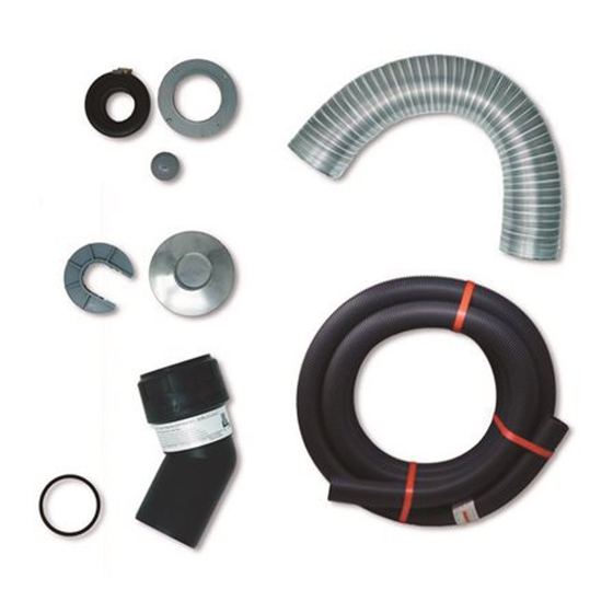
Page 3: Included Accessories
2.Included Accessories The following accessories are included. Check for any missing items before starting installation. Part Shape Q'ty Part Shape Q'ty Flex Feeder Installation Manual (This document) Base Junction Support ・ Clamp x3 "Step-1" EZTR 25 Feet Start Up Guide Base Junction Adapter Set Flex Pipe 2"... -
Page 4: General Safety
3.General Safety DANGER Checkup ・ If similar flexible vent has already been installed, it must be replaced with this designated new Flex Vent Kit. WARNING ・ Flex Vent 2" Kit is designed only for installation inside of B-Vent wall. Do not use it for other installation method. Also do not use it outdoor. -
Page 5: Before Installation
CAUTION ・ Check for any damage to components that may have occurred during transportation before installation. ・ Consult with the customer regarding the location of installation. ・ Do not install this Flex Vent 2" Kit in a place where it may be subject to falling objects, such as under shelves. ・... - Page 6 5ft. 25 feet or less More than 25 feet 6.Vent length from the top of unit to the rain cap. If you need more than 25 feet of Flex pipe contact Noritz America 1-866-766-7489...
- Page 7 Mark " " if each condition Check point Can be installed(OK) Cannot be installed(NG) is matched. 40℉(5℃) or less More than 40℉(5℃) *Refer to page 4 7.Ambient temperature where unit is installed. 40°F (5°C) Cannot access Rain Cap(High Can access Rain Cap pitch etc.) 8.
- Page 8 5.Sample of the Venting system ■ The pictured image of the system consisted of this Vent Kit and the explanation of the name of the components The image of the Flex Vent 2" Kit system is as listed below. Only when the venting components and the water heater are installed correctly, the customer can use the hot water correctly and safely.
-
Page 9: Installation
・ Max. Straight Vent Length: 35'(10.5m). Note that the kit comes with approximately 25' of venting. If you need more than 25 feet of Flex pipe contact Noritz America 1-866-766-7489. Be sure to do ・ Max. allowable 45 degree elbows(B-Vent) are 2 elbows. - Page 10 Step Installation Procedure(ex. @Garage) Necessary Tool 1 Remove the B-Vent between bottom of ceiling and tank type water heater. 2 Drain and remove the tank type water heater. 3 Use a measuring tape to measure from the bottom of the "④B-Vent" to the roof termination to get the total length of the vent run.
- Page 11 Step Installation Procedure(ex. @Garage) Necessary Tool 4 Grab Bag Labeled "Step-1" for this step of the installation. Measure "④B-Vent" Diameter ※Installation for 3" or 4" where "④B-Vent" does not come down through the ceiling. Remove the four screws from "⑤A Base Junction Adapter" Phillips Head Place and center "⑤A Base Junction Adapter"...
- Page 12 Step Installation Procedure(ex. @Garage) Necessary Tool 6 Push the "⑫Flex Feeder" into the tip of the "③Flex Pipe 2"". ③Flex Pipe 2" ⑫ ⑫Flex Feeder Install the " Flex Feeder" always, even in the case of straight B-Vent runs. Be sure to do ⑫...
- Page 13 Step Installation Procedure(ex. @Garage) Necessary Tool Take extra care to ensure that the "③Flex Pipe 2"" does not slip by checking the mark you made on the "③Flex Pipe 2"". Firmly tighten "③Flex Pipe 2"" with "⑥C. Flex Flat head Pipe Clamp", but be careful not to over tighten as it may distort the "③Flex Pipe 2"".
- Page 14 Step Installation Procedure(ex. @Garage) Necessary Tool 10 Take off the existing rain cap and place it on the area where it does not fall from the rooftop. Wet Towel ※Make sure the inside surfaces of the "④B-Vent" are clean to ensure a good seal of the parts in this step. Step-2 11 Use a marker to mark the original position of the "③Flex Pipe 2"", at "④B-Vent"'s upper tip.
- Page 15 Step Installation Procedure(ex. @Garage) Necessary Tool 13 Use a marker to mark the cutting position. Mark PVC Cutter 3 ribs Box Cutter ※All cuts must be made at right angle to the pipe. All field cuts must be deburred. ※Take precaution not to drop debris into "③Flex Pipe 2"". In case debris is dropped, remove from the lower end of the "③Flex Pipe 2"".
- Page 16 Step Installation Procedure(ex. @Garage) Necessary Tool 15 Grab Bag Labeled "Step-3" and necessary tools for this step of the installation. Mount the water heater at the appropriate height according to the chart below, connect the gas, cold and hot water lines, and drain pipes. Follow the equipment's installation manual on how to set the equipment's clearance from combustibles.
- Page 17 Step Installation Procedure(ex. @Garage) Necessary Tool 16 Insert "⑧Rigid 45 Elbow Set" to the equipment's vent connector pipe. When inserting "⑧Rigid 45 Elbow Set", there is tension when it passes through the o-ring within the equipment’s vent connector pipe. Continue to insert "⑧Rigid 45 Elbow Set" until it is firmly seated all the way into the base of the vent connector pipe.
- Page 18 Step Installation Procedure(ex. @Garage) Necessary Tool 【Point】 When performing the final cut, make the first cut of the "③Flex Pipe 2"" longer to avoid cutting the "③Flex Pipe 2"" too short. It is easy to determine the length by following the 【Point】 below and matching the dimension using the below figure. 【Point】...
- Page 19 Step Installation Procedure(ex. @Garage) Necessary Tool 18 Pull "⑦Flex Sleeve" over "③Flex Pipe 2"" under the ceiling. Then, push into the bottom of "⑥Base Junction Support". And check that "③Flex Pipe 2"" is sticking out from "⑦Flex Sleeve". (If it is not sticking out,cut "⑦Flex Sleeve" until "③Flex Pipe 2"" sticks out.) ⑦Flex Sleeve 【Point】...
- Page 20 Step Installation Procedure(ex. @Garage) Necessary Tool 20 See below chart and set "⑨Flex Vent 2" Gasket" onto the tip of "③Flex Pipe 2"". ⑨Flex Vent 2" Gasket 【Point】 Correct way of setting "⑨Flex Vent 2" Gasket". 21 Pull out "⑧Rigid 45 Elbow Set", which are tentatively locked to the equipment's vent connector pipe. Insert the "③Flex Pipe 2""...
-
Page 21: Carbon Monoxide Poisoning
Step Installation Procedure(ex. @Garage) Necessary Tool 22 Attach "⑧Rigid 45 Elbow Set" assembly back onto the unit and secure. When inserting "⑧Rigid 45 Elbow Set", there is tension when it passes through the o-ring within the equipment’s vent connector pipe. Continue to insert "⑧Rigid 45 Elbow Set" until it Flat head Screwdriver reaches the all the way to the base of the equipment vent connector pipe. -
Page 22: Maintenance
Step Installation Procedure(ex. @Garage) Necessary Tool 26 Extend the lower end of "⑦Flex Sleeve" to the sleeve clamp connector of the upper portion of equipment. Then secure with "2×⑩Fastening Screws", and apply "⑪Aluminum tape" covering the connecting part. Make sure that it is firmly fixed by pulling by hand. ※Do not stretch the "⑦Flex Sleeve"... -
Page 23: Parts Lists
25 Feet - Flex Pipe 2" - LE EZ2FVP25-1 ⑤ Base Junction Adapter Set EZ2FVBJADS-1 ⑥ Base Junction Support (w/o hole) EZ2FVBJS-1 ⑦ Flex Vent 2" Sleeve EZ2FVS ⑧ Flex Vent 2" Rigid 45 Elbow Set - LE EZ2FVR45ELB-1 ⑨ Flex Vent 2" Gasket for EZ2FVK-1 EZ2FVK-1-G... - Page 24 Aluminum tape ⑫ Flex Feeder - LE EZ2FVF-1 Flex Vent 2" Kit 25 Feet Installation Manual EZ2FVK-1-LT (This document) EZTR 25 Feet Start Up Guide EZ2FVK-1-SUG Packing Box for Flex Vent 2" Kit 25 Feet EZ2FVK-1-BOX * "No." indicated on this page corresponds to the number on the applicable component on page 8.
Need help?
Do you have a question about the EZ2FVK-1 and is the answer not in the manual?
Questions and answers