
Subscribe to Our Youtube Channel
Related Manuals for LG YD Series


Summary of Contents for LG YD Series
- Page 1 YD Series Non-AFE user manual LG Electronics Air-Conditioning (Shandong) Co,Ltd supervised...
-
Page 2: Table Of Contents
Contents Chapter 0 Instruction ........................ 0 Chapter 1 Safety Precautions 1.1 Before Power On ....................1-1 1.2 Wiring ......................... 1-2 1.3 Before Operation ......................1-2 1.4 Parameter Setting ....................1-3 1.5 Operation ........................1-3 1.6 Inspection, Maintenance and Replacement ..............1-4 Chapter 2 Model Instruction .................... -
Page 3: Chapter 0 Instruction
Chapter 0 Instruction 0.1 Instruction Thank you for purchasing the frequency converter designed and produced by LG Electronics Air-Conditioning (Shandong) Co,Ltd and produced by Wuxi Youlikang Electrical Appliance Co., Ltd. In order to fully utilize the functions of this frequency conversion cabinet and ensure user safety, please read this operation manual carefully. -
Page 4: Chapter 1 Safety Precautions
Chapter 1 Safety Precautions 1.1 Before Power On Warning The main circuit and terminal cable connection must be correct, three input terminals (R, S, T) are for power supply, absolutely, you can’t mix with the motor output (U, V, W); if so, it will damage inverter panel. -
Page 5: Wiring
1.2 Wiring Warning Be sure to turn off the main power supply before any inverter or wiring, so as to avoid electric shock and fire. The wiring project personnel shall have the relevant professional knowledge, to avoid electric shock and fire. -
Page 6: Parameter Setting
1.4 Parameter setting Attention When you are debugging parameters, you need to read the instruction manual. When making parameter modifications ,the professional or qualified technical certification personnel are required to avoid the damage to the machine or personnel in commissioning process. -
Page 7: Inspection, Maintenance And Replacement
allowable range of the motor and the load. When you use the circuit breaker or electromagnetic contactor to the front end, please pay attention to the specifications and related settings. Please do not check the signal on the circuit board when the inverter is in operation. Warning ... -
Page 8: Chapter 2 Model Instruction
○ 4 ○ 5 ○ 6 ○ 7 ○ 8 ○ 9 ○ 10 ○ 11 ○ 12 ○ 13 ○ 14 ○ 15 ○ 1 YD series VFD(YD 系列变频器) ○ 2 Use Motor Rated Load Amps (NMRA) value(适用电机额定电流) 0236:0~236A 0302:237~302A 0472:303~472A 0605:473~605A 0708:606~708A... - Page 9 ○ 7 Terminal model(接线端子形式) 1= Each terminal one hole (单孔端子) 2= Each terminal two holes(双孔端子) 3= Aluminum Terminal(铝合金端子) ○ 8 Power meter optional(功率表选配) X= None(无功率表) W= Power meter optional(有功率表) ○ 9 Current meter and Voltage meter optional(电压、电流表选配) X= None(无电压、电流表) B= Current meter and Voltage meter optional(有电压、电流表) ○...
- Page 10 2.2 Specification table of inverter (变频柜选型规格表) Specification table of inverter Rated Current Applicable current overload Structure Frame Cooling way 236A 0A-236A Frame1 Air-cooling 302A 237A-302A 472A 303A-472A Frame2 605A 473A-605A Liquid air 708A 606A-708A 110% cooling Frame3 906A 709A-906A 1100A 907A-1100A water-coolin 1236A...
-
Page 11: Chapter 3 Electrical Wiring
Chapter 3 Electrical Wiring Instructions 3.1 Terminal function instructions 3.1.1 Main loop Terminal function instructions Terminal symbol Wiring object Points for attention Alternating current power supply 380-460 VAC +10%~-10% Motor interline impedance needs to be balanced, Load motor no short-circuit phenomenon; Motor wire and ground PE impedance need to be open. -
Page 13: Chapter 4 Surrounding Environment And Installation
Chapter 4 Surrounding Environment and Installation 4.1 Environment The installation environment of inverter panel cabinet can direct influence on the function and life span. Therefore, the installation environment around inverter must meet the following conditions: Protection IP21/IP54 Protection Level Applicable Environment External Circulating 15~40℃... -
Page 14: Dimension And Mounting Holes Position
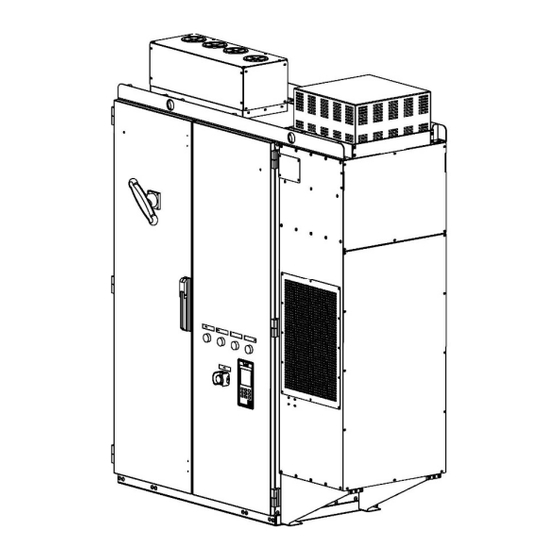
4.2 Dimension And Mounting Holes Position Frame2 303A-605A... - Page 15 Frame3 606A-906A...
- Page 16 Frame4 907A-1386 4.3 Inverter Panel Peripheral Equipment Wiring And Attentions Attentions 1. Within minutes after the input power is cut off, the main circuit may still have high voltage. The operation can be carried out only after confirming that the DC bus voltage is lower than 36V;...
- Page 17 3. Never connect the inverter output terminals U, V, W to the AC power supply; 4. The grounding terminal E of the inverter cabinet must be grounded; 5. Please do not test the internal components of the inverter, these semiconductor parts are vulnerable to high pressure and damaged;...
-
Page 18: Chapter 5 Software Index
Chapter 5.1 Software Index 5.1 LCD panel usage instructions 5.1.1 Panel function instructions The following is the appearance of the LCD panel: LCD display,160*160 pixel Function keys F1、F2、 F3 (3) The operation keys PC communication interface X30 communication interface The panel supports three function keys (F1, F2, F3) and six operation keys (up, down, left, right, ESC, ENT/RST). -
Page 19: Display Instructions
The function of the operation keys as follows: 1>. The function of the operation keys Name Function Up key Please click this button when you select the method, group, 【↑】 function, parameter name, setting value (increase), etc. Please click this button when you select the method, group, Down key 【↓】... - Page 20 Inverter status: State 1: running Unused 1: inversion state Unused Unused 1: inverter ready Unused Unused ○ 2 Inverter status: report an error: The monitor is in the lower center of the screen. For example, when the inverter reports low-voltage alarm, the panel screen is shown as follows: The inverter is in low-voltage state, and "UV"...
- Page 21 3>. Press the key 【F3】 to enter programming mode In this mode, the internal parameters of the inverter can be set. ★ When entering the programming mode, you need to set the permission of use parameters. See the content of the programming mode for details. In addition, the person who uses the programming mode should has considerable professional ability and know how to use the inverter.
- Page 22 Select the paramter group through【↑】/【 】. ↓ 【ESC】 【ENT/RST】 Enter the parameter group interface. 【ESC】 【ENT/RST】 Enter the parameter group interface. 【ESC】 【ENT/RST】 Enter the parameter group interface.
- Page 23 5.1.3 Screen and parameter instruction The parameter tree is as follows: 参数组 参数列表 参数 U1-xx 状态监视 U1-01...U1-53 U-群组 监视参数 U3-01...U3-09 U3-xx 异常记录 A-群组 A1-04 A1-xx 环境设定模式 环境参数 B-群组 B1-xx 运行模式选择 B1-01...B1-03、B1-06 应用参数 C1-01...C1-02 C1-xx 加减速时间 C-群组 调整参数 群 C6-xx 载波频率 C6-01、C6-06 组...
- Page 24 Select the parameter groups through 【↑】/【 】 ↓ 【ENT/RST】 【ESC】 Enter the parameter list interface 【ESC】 【ENT/RST】 Enter the parameter display interface 【ENT/RST】 【ESC】 Enter the parameter display interface...
-
Page 25: Parameter Operation Example
5.1.4 Parameter operation example 1>. Unchangeable parameters: (Read Only): 【ESC】 【ENT/RST】 For unchangeable parameters: * Only the [ESC] key is available! →No change in parameters 2>. Variable parameter: 【ESC】 【ENT/RST】 【ENT/RST】... -
Page 26: Password Structure
Setting Modification value through 【↑】or【↓】 , 【ENT/RST】 or【ESC】 5.1.5 Password structure 5.1.5.1 Password level ●LG customer parameters: LG customer parameters can display the contents (current state of frequency converter, bus voltage, current, frequency instruction, current fault code) (F1 monitoring and running interface) - Page 27 You can check the history of the fault code and all the monitoring parameters (F3 interface) ● LG parameters: 1)The parameters can be set by LG ; You can check the history code of the fault and all the monitoring parameters.
- Page 28 【ESC ESC】 5.1.5.4 LG password reset 【ENT/RST】+【↑】 ,Setting password value Setting password value Correct password orrect password Wrong password 【ESC】 Exit password 【ENT/RST】 modification interface False alarm False alarm Display 2s 【ENT/RST】 ,password reset 【 5-11...
- Page 29 【ESC】 Quit the password 【ENT/RST】, reconfirm the password modification interface 【ENT/RST】+【↑】 ,Setting password value Different with the Same as the new password new password 【ENT/RST】 Error Alert Display 2s 5-12...
-
Page 30: Parameter Function Instruction
Chapter 5.2 Software Index (Parameters instructions) 5.2 Parameter function instruction User parameter group 5.2.1 U Group: Summary of User Monitoring Parameters Simulation monitoring Minimum Function Parameter Name Contents output unit Frequency Monitoring and Setting of U1-01 10V/maximum frequency 0.01Hz instruction frequency instruction value U1-02 Output frequency... - Page 31 IGBT IGBT overtemperature U1-50 overtemperature overtemperature No output No output protection set point protection point protection point Reactor Reactor overtemperature U1-51 overtemperature overtemperature No output No output protection set value protection point protection point Display the type code of U1-52 Inverter type code Inverter type code No output...
-
Page 32: A Group: Programming Environment Parameter Settings
*2 LCD Keypad display: Programming parameter group 5.2.2 A Group : Programming environment parameter setting A1- 03 Restore factory Values 【0】 【01150】: Restore 50Hz system factory values Range 【01160】: Restore 60Hz system factory values 【0】 No initialization 01150 The parameter values restore to 50Hz system 01160 The parameter values restore to 60Hz system Note:... -
Page 33: C Group: Performance Parameter Adjustment
After the stop command issued, the inverter stop the motor. B1-03 = 0, after issuing the shutdown command, the output of the inverter will slow down to zero from the current frequency according to the deceleration time C1-02. Picture B1-03-01 B1-03 = 1, after issuing the shutdown command, the output of the inverter will immediately stop, and the motor will run freely from the current frequency and decelerate to zero. - Page 34 UC800 setting frequency ∗ C1 − 02( deceleration time E1 − 06 rated motor frequency Attention: The actual acceleration time also need to add the delayed time ‘Tid’ limited by CPU algorithm and a large current during the process. The actual deceleration time also need to add the delayed time limited by CPU algorithm and rebound voltage during the process.
- Page 35 5.2.5 E Group E: Motor parameters E1- 06 motor rated frequency unit Hz Range According to customer’s order 【 0.00~650.00 】Hz E1- 13 motor rated voltage unit V Range According to customer’s order 【 0.0~510.0 】V E2- 01 unit A Motor rated current Range Table A...
-
Page 36: O Group : Protective Functional Parameters
When the IGBT temperature is higher than the setting value, the cold water pump moves. L6- 07 Closing temperature of cold water pump unit ℃ Range 【 10~80 】℃ 【50】℃ When IGBT temperature lower than the setting value, the cold water pump stops. L8- 01 IGBT Overtemperature Protection Settings unit... -
Page 37: Chapter 6 Abnormal Diagnosis And Troubleshooting
Chapter 6 Abnormal diagnosis and trouble shooting 6.1 General rules Inverter cabinet fault detection and early warning / self diagnosis function. When the inverter detects a fault, the code is displayed on the LCD operator, The output of the fail contact is acting, the inverter output is cut off, and the motor is free to stop (in some areas of failure, the method of shutdown is optional.). - Page 38 Fault Possible reasons Solutions phenomenons 1. Check whether the contactor cable is loose Power on (or 2.Check whether the contactor has faults operation) report 1. Soft start contactor does not engage 3. Check whether the 24V power supply of contactor has faults 4.
- Page 39 The inverter has three levels of error message display, as follows: Item Level Inverter Reaction Supplement The inverter stops and displays the Inverter Fault Alarm (Fault) Red level fault code Inverter Stop Display Inverter Warning Alarm (Warning) Yellow level Warning Code 6.2 Fault detection function- [Inverter stop] When failure occurs, refer to the table 6.1 for possible reasons and take appropriate measures.
- Page 40 add braking resistance 4. Add braking unit and resistance Emergency stop The emergency stop button is The inverter emergency stop button is Check the emergency stop pressed pressed button of inverter Missteering of pump Control failure of water valve Check water valve controller alarm Contact after-sales service in inverter failure...
- Page 41 LCD display Illustration Possible reasons Corrective action Input owe phase 1. The three-phase input power supply is Input owe phase The inverter input side owe abnormal 1. Check and eliminate problems in phase or there is a large 2. Lightning protection board is abnormal peripheral lines unbalanced voltage.
- Page 42 and inverter has been abnormal 3, Panel (hand) or inverter motherboard 2. Replace the D-sub cable. for 5 times continuously fault. 3. Replace the panel (handwriting device) or inverter motherboard. 2. Communications reset automatically after re - establishment. Low voltage The main circuit voltage is too low: The DC bus voltage is lower...
- Page 43 Error in communication between handwriting device and X30: Exceeded cm-06 (communication abnormal detection time), no communication was received. After the communication is disconnected, stop the machine. if you need to reset, please press the reset button Note: Currently CE1 and UV are not stored in U3 group. 6.3 Warning alarm/self-diagnostic detection function –...
- Page 44 LCD display Illustration Possible reasons Corrective action input parameters during and parameter properties of (illegal input)- attempted to operation the inverter "Input mode error modify the parameter 2. Attempt to input and read 2. Reconfirm parameter "property is unmodifiable dedicated data properties during operation"...
Need help?
Do you have a question about the YD Series and is the answer not in the manual?
Questions and answers