Toro 72065 Operator's Manual
Riding mower with 60in or 72in turbo force rear discharge mower
Hide thumbs
Also See for 72065:
- Operator's manual (300 pages) ,
- Operator's manual (72 pages) ,
- Setup instructions (8 pages)
Table of Contents
Advertisement
Quick Links
Register at www.Toro.com.
Original Instructions (EN)
Z Master
®
Series Riding Mower
With 60in or 72in TURBO FORCE
Discharge Mower
Model No. 72028—Serial No. 408863644 and Up
Model No. 72029—Serial No. 407600000 and Up
Model No. 72065—Serial No. 408864664 and Up
Model No. 72074—Serial No. 408961606 and Up
Form No. 3444-444 Rev C
Professional 7500-D
®
Rear
*3444-444*
Advertisement
Table of Contents

Related Manuals for Toro 72065


Summary of Contents for Toro 72065
- Page 1 With 60in or 72in TURBO FORCE ® Rear Discharge Mower Model No. 72028—Serial No. 408863644 and Up Model No. 72029—Serial No. 407600000 and Up Model No. 72065—Serial No. 408864664 and Up Model No. 72074—Serial No. 408961606 and Up *3444-444* Register at www.Toro.com. Original Instructions (EN)
- Page 2 Authorized Service requirements, the actual engine torque on this class Dealer or Toro Customer Service and have the model of mower will be significantly lower. Please refer to and serial numbers of your product ready.
-
Page 3: Table Of Contents
Contents The safety-alert symbol (Figure 2) appears both in this manual and on the machine to identify important safety messages that you must follow to avoid Safety ............... 5 accidents. This symbol will appear with the word General Safety ........... 5 Danger, Warning, or Caution. - Page 4 Checking the Fuel Lines and Connections..........40 Electrical System Maintenance ......41 Electrical System Safety ........41 Servicing the Battery......... 41 Servicing the Fuses .......... 42 Drive System Maintenance ........43 Checking the Seat Belt ........43 Adjusting the Tracking ........43 Checking the Tire Pressure.......
-
Page 5: Safety
Safety This machine has been designed in accordance with EN ISO 5395. General Safety This product is capable of amputating hands and feet and of throwing objects. Always follow all safety instructions to avoid serious personal injury or death. • Read and understand the contents of this Operator’s Manual before starting the engine. -
Page 6: Slope Indicator
Slope Indicator g011841 Figure 3 You may copy this page for personal use. 1. The maximum slope you can operate the machine on is 15 degrees. Use the slope chart to determine the degree of slope of hills before operating. Do not operate this machine on a slope greater than 15 degrees. Fold along the appropriate line to match the recommended slope. -
Page 7: Safety And Instructional Decals
Safety and Instructional Decals Safety decals and instructions are easily visible to the operator and are located near any area of potential danger. Replace any decal that is damaged or missing. decalbatterysymbols Battery Symbols Some or all of these symbols are on your battery. 1. - Page 8 decal112-9028 112-9028 1. Warning—stay away from moving parts; keep all guards and shields in place. decal116-5988 116-5988 1. Parking brake—engaged 2. Parking brake—disengaged decal107-3069 107-3069 1. Warning–there is no rollover protection when the roll bar is down. 2. To avoid injury or death from a rollover accident, keep the roll bar in the raised and locked position and wear the seat belt.
- Page 9 decal126-8383 126-8383 Note: This machine complies with the industry standard stability test in the static lateral and longitudinal tests with the maximum recommended slope indicated on the decal. Review the instructions for operating the machine on slopes in the Operator’s Manual as well as the conditions in which you would operate the machine to determine whether you can operate the machine in the conditions on that day and at that site.
- Page 10 decal126-9278 126-9278 1. Engine—Off 4. Push the bottom of the button to lower the deck. 2. Engine—On 5. Push the top of the button to raise the deck. 3. Engine—Start decal126-9279 126-9279 1. Read the instructions before servicing or performing 7.
- Page 11 decal135-0328 135-0328 1. Torque the wheel lug nuts 2. Read and understand to 129 N∙m (95 ft-lb). the Operator's Manual before performing any decal126-9280 126-9280 maintenance; check the torque after the first 100 For Models with 152 cm (60-inch) or 183 cm (72-inch) hours, then every 500 Decks with Rear Discharge hours, thereafter.
- Page 12 1. Rotating driveline hazard/entanglement hazard; belt—stay away from moving parts; keep all guards and shields in place. decal135-1432 135-1432 decal135-2837 135-2837 1. Read the Operator’s Manual for more information; Use red Toro wet-clutch transmission fluid; do not use green hydraulic fluid.
-
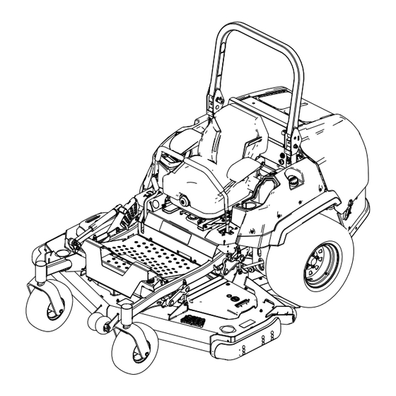
Page 13: Product Overview
Product Overview g227303 Figure 4 1. Height-of-cut pin 7. Motion-control lever 2. Parking-brake lever 8. Fuel-tank cap 3. Monitor/controls 9. Anti-scalp roller 4. Roll bar 10. Skid 5. Engine screen 11. Caster wheel 6. Audible alarm and power point 12. Mower deck... -
Page 14: Controls
Controls Become familiar with all the controls before you start the engine and operate the machine. Control Panel g228164 Figure 6 g225792 Horizon Display Monitor Figure 5 1. Horizon display monitor 3. Key switch 1. Screen 3. Buttons 2. LED status light 2. - Page 15 Blade-Control Switch (Power • A fast chirp sound indicates critical errors. Takeoff) • A slow chirping sound indicates less critical errors, such as required maintenance or service intervals. The blade-control switch (PTO) engages and Note: During startup, the alarm sounds briefly to disengages power to the mower blades (Figure verify functionality.
-
Page 16: Specifications
Overall Length To ensure optimum performance and continued safety Roll bar up or down 255.5 cm (100-5/8 inches) certification of the machine, use only genuine Toro replacement parts and accessories. Replacement Overall Height parts and accessories made by other manufacturers... -
Page 17: Before Operation
Fuel Safety Operation • Fuel is extremely flammable and highly explosive. A fire or explosion from fuel can burn you and Note: Determine the left and right sides of the others and can damage property. machine from the normal operating position. –... -
Page 18: Adding Fuel
Adding Fuel Fill the fuel tank to the bottom of the filler neck (Figure Note: Do not fill the fuel tank completely full. Recommended Fuel The empty space in the tank allows the fuel to expand. The engine runs on clean, fresh diesel fuel with a minimum cetane rating of 40. -
Page 19: Performing Daily Maintenance
Performing Daily Lower the roll bar to the down position (Figure Maintenance Before starting the machine each day, perform the Each Use/Daily procedures listed in Maintenance (page 33). Breaking in a New Machine New engines take time to develop full power. Mower decks and drive systems have higher friction when new, placing additional load on the engine. -
Page 20: Using The Safety-Interlock System
g230650 Figure 10 1. Indicators display when the interlock components are in the correct position g008619 Figure 9 Testing the Safety-Interlock 1. Engaged 2. Partially engaged—do not System operate the machine with the ROPS in this position. Service Interval: Before each use or daily Test the safety-interlock system before you use the Using the Safety-Interlock machine each time. -
Page 21: Positioning The Seat
Positioning the Seat Changing the Seat Suspension The seat can move forward and backward. Position the seat where you have the best control of the The seat is adjustable to provide a smooth and machine and are most comfortable (Figure 11). -
Page 22: Rollover Protection System (Rops) Safety
ROPS components from the machine. • Use only accessories and attachments approved by Toro. • Ensure that the seat belt is attached and that you • This machine produces sound levels in excess can release it quickly in an emergency. -
Page 23: Slope Safety
Authorized Service Dealer to inspect the ROPS. become unstable. • Use only Toro approved accessories and attachments for the ROPS. Slope Safety • Slopes are a major factor related to loss of control and rollover accidents, which can result in severe injury or death. -
Page 24: Operating The Parking Brake
Operating the Parking Engaging the Blade-Control Switch (PTO) Brake Note: Engaging the blade-control switch (PTO) with Always engage the parking brake when you stop the the throttle position at half or less causes excessive machine or leave it unattended. wear to the drive belts. Engaging the Parking Brake Park the machine on a level surface. -
Page 25: Starting The Engine
Starting the Engine Shutting Off the Engine Important: Do not engage the starter for more CAUTION than 5 seconds at a time. If the engine fails to start, wait 15 seconds between attempts. Failure Children or bystanders may be injured if they to follow these instructions can burn out the move or attempt to operate the machine while starter motor. -
Page 26: Using The Motion-Control Levers
Using the Motion-Control Driving the Machine Levers The drive wheels turn independently, powered by hydraulic motors on each axle. You can turn 1 side in reverse while you turn the other forward, causing the machine to spin rather than turn. This greatly improves the machine maneuverability but may require some time for you to adapt to how it moves. -
Page 27: Driving In Reverse
Adjusting the Height of Cut Adjust the height of cut from 25 to 140 mm (1 to 5-1/2 inches) in 6 mm (1/4 inch) increments by moving the clevis pin into different hole locations. With the engine running, push the deck-lift switch rearward until the mower deck is fully raised, and release the switch immediately. -
Page 28: Adjusting The Anti-Scalp Rollers
Adjusting the Anti-Scalp Rollers For maximum deck flotation, install the rollers 1 hole position lower. Rollers should maintain a 6 mm (1/4 inch) clearance to the ground. Do not adjust the rollers to support the deck. Park the machine on a level surface. Disengage the blade-control switch (PTO), move the motion-control levers to the N EUTRAL... -
Page 29: Adjusting The Skids
Adjusting the Skids Mount the skids in the lower position when operating at heights of cut greater than 51 mm (2 inches) and in a higher position when operating at heights of cut lower than 51 mm (2 inches). Adjust the skids as shown in Figure g035646 Figure 28... -
Page 30: Operating Tips
It is best to cut only about a third of the grass blade. genuine Toro replacement blade. Cutting more than that is not recommended unless grass is sparse, or it is late fall when grass grows more slowly. -
Page 31: After Operation
Transporting the Machine After Operation Use a heavy-duty trailer or truck to transport the machine. Use a full-width ramp. Ensure that the trailer After Operation Safety or truck has all the necessary brakes, lighting, and marking as required by law. Please carefully read all the safety instructions. -
Page 32: Unloading The Machine
If using a trailer, connect it to the towing vehicle and connect the safety chains. If applicable, connect the trailer brakes and lights. Lower the ramp, ensuring that the angle between the ramp and the ground does not exceed 15 degrees (Figure 30). -
Page 33: Maintenance
• Check the alternator-belt tension. Every 100 hours • Change the engine oil and filter if not using Toro Premium Engine Oil, but any oil Every 200 hours meeting API classification CJ-4 or higher or as stated in Engine-Oil Specifications. - Page 34 • Grease the caster pivots (more often in dirty or dusty conditions). • Service the air cleaner (More frequently in extremely dusty or dirty conditions). • Change the engine oil and filter if using Toro Premium Engine Oil (API classification CK-4 or higher) (more often in dirty or dusty conditions).
-
Page 35: Lubrication
Lubrication Greasing the Machine Service Interval: Every 400 hours/Yearly (whichever comes first)—Grease the deck-idler pivots. Yearly—Grease the deck drive PTO. Grease more frequently when operating conditions are extremely dusty or sandy. Grease Type: No. 2 lithium or molybdenum grease Park the machine on a level surface, disengage the blade-control switch, and engage the parking Lubricating the Drive brake. -
Page 36: Greasing The Caster Pivots
Greasing the Caster Pivots Remove a spacer nut from the axle assembly in the caster wheel. Service Interval: Every 400 hours/Yearly (whichever Note: Thread-locking compound has been comes first) (more often in dirty or applied to lock the spacer nuts to the axle. dusty conditions). -
Page 37: Engine Maintenance
Engine Maintenance Servicing the Air Cleaner Note: If the foam gasket in the cover is damaged, replace it. Engine Safety Important: Avoid using high-pressure air, which • Keep your hands, feet, face, clothing, and other could force dirt through the filter into the intake body parts away from the muffler and other hot tract. -
Page 38: Servicing The Engine Oil
After the first 200 hours—Change the engine oil and filter. Every 200 hours—Change the engine oil and filter if not using Toro Premium Engine Oil, but any oil meeting API classification CJ-4 or higher or as stated in Engine-Oil Specifications. -
Page 39: Inspecting The Engine-Valve Clearance
Changing the Engine Oil and Filter If possible, run the engine just before changing the oil because warm oil flows better and carries more contaminants than cold oil. Park the machine on a level surface, disengage the blade-control switch (PTO), and engage the parking brake. -
Page 40: Fuel System Maintenance
Replacing the Water Fuel System Separator Maintenance Service Interval: Every 400 hours—Replace the DANGER fuel-filter canister for the water separator (more often in dirty and In certain conditions, fuel is extremely dusty conditions). flammable and highly explosive. A fire or explosion from fuel can burn you and others and can damage property. -
Page 41: Electrical System Maintenance
Electrical System WARNING Incorrect battery cable routing could damage Maintenance the machine and cables causing sparks. Sparks can cause the battery gasses to explode, resulting in personal injury. Electrical System Safety • Always disconnect the negative (black) • Disconnect the battery before repairing the battery cable before disconnecting the machine. -
Page 42: Installing The Battery
Installing the Battery Note: Do not run the machine with the battery disconnected, electrical damage may occur. Note: Position the battery in the tray with the terminal posts opposite from the hydraulic tank. g000960 Figure 44 1. Positive battery post 3. -
Page 43: Drive System Maintenance
Drive System Align the levers in the front-to-rear position by bringing the levers together to the N EUTRAL Maintenance position, and slide them until they are aligned, then tighten the bolts (Figure 47). Checking the Seat Belt Service Interval: Before each use or daily Inspect the seat belt for wear, cuts, and proper operation of the retractor and buckle. -
Page 44: Checking The Tire Pressure
Checking the Tire Pressure Adjusting the Caster-Pivot Bearing Service Interval: Every 50 hours/Monthly (whichever comes first) Service Interval: Every 500 hours/Yearly (whichever Rear tire air pressure specification: 124 kPa (18 comes first) psi). Park the machine on a level surface, disengage Note: the blade-control switch, and engage the parking The caster tires are semi-pneumatic tires and... -
Page 45: Servicing The Gearbox
Checking the Gearbox-Oil Level Every 400 hours Service Interval: Every 50 hours If the oil becomes contaminated, contact your Toro Distributor because the system must be flushed. Use SAE 75W-90 synthetic gear lube. Contaminated oil looks milky or black when compared Park the machine on a level surface and engage to clean oil. -
Page 46: Cooling System Maintenance
Cooling System Maintenance Cooling System Safety • Swallowing engine coolant can cause poisoning; keep out of reach from children and pets. • Discharge of hot, pressurized coolant or touching a hot radiator and surrounding parts can cause severe burns. – Always allow the engine to cool at least 15 minutes before removing the radiator cap. -
Page 47: Changing The Engine Coolant
Note: If debris remains, repeat until clean. Operate engine until the engine thermostat opens and the coolant is circulating through the Lower the hood. radiator core. Start the engine to ensure that the fan functions As air purges from the engine block and the properly. -
Page 48: Brake Maintenance
Brake Maintenance Adjusting the Parking Brake Service Interval: After the first 100 hours Every 400 hours Check to ensure that parking brake is adjusted properly. Follow this procedure also whenever you have removed or replaced a brake component. Park the machine on a level surface, disengage the blade-control switch, and engage the parking brake. -
Page 49: Belt Maintenance
Belt Maintenance Repeat steps through until a visible gap is achieved and the wheel hub rotates freely. Repeat this procedure for the other side. Inspecting the Belts Note: The brake should fully disengage when the brake is in the released position. Service Interval: Every 50 hours Rotate the drive wheel release handle to Replace the belt if it is worn. -
Page 50: Checking The Alternator-Belt Tension
Checking the square hole, install the belt around the idler pulley (Figure 55). Alternator-Belt Tension Install the belt covers. Service Interval: Every 100 hours Apply 44 N (10 lb) of force to the alternator belt, midway between the pulleys. If the deflection is not 10 mm (3/8 inch), loosen the alternator mounting bolts (Figure 56). -
Page 51: Controls System Maintenance
Controls System Maintenance Adjusting the Control-Handle Position There are 2 height positions for the control levers—high and low. Remove the bolts to adjust the height for the operator. Park the machine on a level surface, disengage the blade-control switch (PTO), and engage the parking brake. -
Page 52: Adjusting The Motion-Control Damper
Note: Raise the rear of the machine up and support it The wheels should stop turning or slightly with jack stands (or equivalent support) just high creep in reverse. enough to allow the drive wheels to turn freely. Shut off the machine. Remove the electrical connection from the seat Remove the jumper wire from the wire harness safety switch, located under the bottom cushion... -
Page 53: Hydraulic System Maintenance
Note: If the level is not within the notched area Alternate fluids: If the Toro fluid is not available, of the dipstick, add enough high-quality hydraulic Mobil® 424 hydraulic fluid may be used. fluid to raise the level to within the notched area. -
Page 54: Changing The Hydraulic Fluid And Filter
Every 800 hours—Change the hydraulic fluid and filter if using Toro Premium Fill each wheel motor with approximately Transmission/Hydraulic Tractor Fluid. 1.4 L (1.5 US qt) of Toro Premium Disengage the PTO, move the motion-control Transmission/Hydraulic Tractor Fluid. levers to the N... -
Page 55: Mower Deck Maintenance
Mower Deck Maintenance Blade Safety • Inspect the blades periodically for wear or damage. • Use care when checking the blades. Wrap the g006530 blades or wear gloves, and use caution when Figure 65 servicing the blades. Only replace or sharpen the 1. -
Page 56: Removing The Blades
g014973 g014973 Figure 67 Figure 69 1. Blade (in position for measuring) 1. Opposite blade edge (in position for measuring) 2. Level surface 2. Level surface 3. Measured distance between blade and the surface (A) 3. Second measured distance between blade and surface (B) Rotate the same blade 180 degrees so that If the difference between A and B is greater the opposing cutting edge is now in the same... -
Page 57: Installing The Blades
g000553 Figure 72 1. Blade 2. Balancer Repeat this procedure until the blade is balanced. Installing the Blades Install the bushing through the blade with the bushing flange on the bottom (grass) side of the blade (Figure 73). g295816 Figure 70 1. -
Page 58: Leveling The Mower Deck
Apply copper-based lubricant or grease to the threads of the blade bolt as needed to prevent seizing. Install the blade bolt finger-tight. Place a wrench on the flat of the spindle shaft and torque the blade bolt to 75 to 81 N∙m (55 to 60 ft-lb). - Page 59 g232012 Figure 78 1. Single-point height 3. Rear height-of-cut plate adjustment bolt mounting bolt 2. Front height-of-cut plate g231991 Figure 77 mounting bolt 1. Deck adjustment 3. Adjustment nut To adjust the single-point system, first loosen 2. Jam nut the front and rear height-of-cut plate mounting bolts (Figure 78).
- Page 60 adjustment bolt by rotating it counterclockwise (Figure 80). Note: Loosen or tighten the single-point adjustment bolt enough to move the height-of-cut plate mounting bolts at least 1/3 the length of the available travel in their slots. This regains some up and down adjustment on each of the 4 deck links.
-
Page 61: Cleaning
Cleaning Cleaning the Engine and Exhaust System Area Service Interval: Before each use or daily—Clean the engine and exhaust system area. Important: Do not use water to clean the engine. Use low-pressure compressed air. See the engine owner's manual. Park the machine on a level surface, disengage the blade-control switch (PTO), and engage the parking brake. -
Page 62: Storage
Storage Check the condition of the blades; refer to Servicing the Cutting Blades (page 55). Prepare the machine for storage when non-use Storage Safety occurs over 30 days. Prepare the machine for storage as follows: • Shut off the engine, remove the key, and wait for all moving parts to stop before you leave the Add a petroleum-based operator’s position. -
Page 63: Troubleshooting
Troubleshooting Problem Possible Cause Corrective Action The starter does not crank. 1. The blade-control switch is engaged. 1. Disengage the blade-control switch. 2. The parking brake is disengaged. 2. Engage the parking brake. 3. The motion-control levers are not in 3. - Page 64 Problem Possible Cause Corrective Action The machine does not drive. 1. The bypass valves are not closed tight. 1. Tighten the bypass valves. 2. The pump belt is worn, loose, or 2. Change the belt. broken. 3. The pump belt is off a pulley. 3.
-
Page 65: Schematics
Schematics SWITCH PTO SWITCH SEAT BRAKE SWITCH NEUTRAL NEUTRAL SWITCH g229105 Electrical Schematic—Machine with Horizon Display Monitor (Rev. A) - Page 66 POWER DISTRIBUTION MODULE TO HARNESS B CONNECTOR 43 g229107 Electrical Schematic—Yanmar Engine 3TNV80FT (Rev. A)
- Page 67 g229106 Electrical Schematic—Yanmar Engine 3TNV88C (Rev. A)
- Page 68 While the exposure from Toro products may be negligible or well within the “no significant risk” range, out of an abundance of caution, Toro has elected to provide the Prop 65 warnings. Moreover, if Toro does not provide these warnings, it could be sued by the State of California or by private parties seeking to enforce Prop 65 and subject to substantial penalties.
Need help?
Do you have a question about the 72065 and is the answer not in the manual?
Questions and answers