Table of Contents
Advertisement
Quick Links
Advertisement
Table of Contents

Related Manuals for Mizudo ET036


Summary of Contents for Mizudo ET036
- Page 1 MODEL: ET036 Electric Tankless Water Heater Installation and Operation Manual WARNING Please read all instructions before using this water heater. Failure to follow the information in these instructions may result in fire, electric shock, property damage, injury or death.
-
Page 3: Table Of Contents
CONTENTS 1 Safety Information 1.1 Safety Definitions 1.2 General Information 1.3 Important Safety Messages 2 General Information 2.1 Introduction and Explanation 2.2 Dimensions and Connection Points 2.3 Technical Parameters 2.4 Component Diagram 3 Installation 3.1 Installation Instructions 3.2 Prepare for Installation 3.3 Installation Dimensions 3.4 Installation Method 3.5 Water Connections... -
Page 4: Safety Information
Safety Information If you have any questions regarding the 1 Safety Information Ÿ installation, use or operation of this water heater, or if you need any additional installation 1.1 Safety Definitions manuals, please call our technical service line. This manual has safety information and instructions to help you eliminate or reduce the risk of accidents 1.3 Important Safety Messages and injuries. -
Page 5: General Information
General Information 2 General Information DANGER: Burns Water temperatures over 125°F (52°C) can cause severe burns instantly or death from 2.1 Introduction and Explanation scalding. A hot water scalding potential exists if the thermostat on the appliance is The units are designed to supply hot water for a set too high. -
Page 6: Dimensions And Connection Points
General Information 2.2 Dimensions and Connection Points 3.7" (93 mm) 18.5" (471 mm) 10.1" (256 mm) -
Page 7: Technical Parameters
General Information 2.3 Technical Parameters Model ET036 Voltage 240 V Wattage 36 kW Min. Required Circuit Breaker Size 4 X 40 A Max. Amperage 150 A Recommended Wire Size 4 X 8 AWG Min. Water Flow to Activate the Unit 0.92 GPM / 3.5 L/min... -
Page 8: Component Diagram
General Information 2.4 Component Diagram Front Cover Outlet water temperature probe Led Display Hot water connection Control Key Bottom case Heating element Silicon controlled rectifier Copper cup Transformer Thermostat bracket Filter board Thermostat Terminal block Cooling fin Inlet water temperature probe Display assembly Power cord waterproof connector Display board bracket... -
Page 9: Installation
Installation 3 Installation The unit must be installed in a circuit suitable for Ÿ overcurrent. Must be grounded at the breaker panel. 3.1 Installation Instructions This unit must be permanently connected to a Ÿ fixed circuit breaker. If you are not using the unit, WARNING turn off the circuit breaker. -
Page 10: Prepare For Installation
Installation 3.2 Prepare for installation Parts included Electric Tankless User Manual Assembly Kit Water Heater Tools needed (Not included) Hammer Phillips Hammer Drill Ruler Gloves Pencil screwdriver With Concrete Bits 3.3 Installation Dimensions 0.5" (11 mm) 14.1" (359 mm) 12.5" (420 mm) -
Page 11: Installation Method
Installation 3.4 Installation Method 3. Insert M4 screws into the two upper holes, leaving about 0.12 inches to 0.2 inches (3-5mm) 1. Figure out where to mount the water heater unit, not tightly fastened (Fig.3). mark 4 mounting holes on the wall according to the water heater or installation guide. -
Page 12: Water Connections
Installation 3.5 Water Connections 5. Hang the machine on the two previously installed screws, then secure the lower two screws. Finally, tighten the upper two screws (Fig.5). NOTICE Excessive heat from soldering on copper pipes near the Unit may cause damage. The cold water connection to the unit must be disconnected periodically in order to clean the filter screen. -
Page 13: Circuit Layout
Operation 3.6.1 Circuit Layout The cold water connection (inlet) is on the right Ÿ side of the unit, and the hot water connection (outlet) is on the left side of the unit. CAUTION Tankless water heaters are not required to be equipped with a temperature and pressure relief valve (T&P). -
Page 14: Commissioning The Water Heater
Maintenance 3.6.2 Circuit Connection 3.7 Commissioning the Water Heater Please refer to "2.3 Technical Parameters" for the WARNING correct wire and circuit breaker size. In all cases, Open the hot water faucet for a few make sure that the unit is properly grounded. minutes until water flow is continuous and all air is purged from water pipes. -
Page 15: Operation
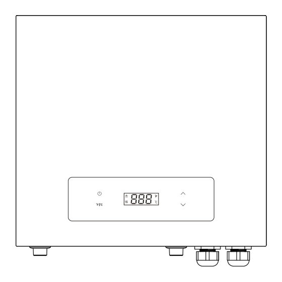
Maintenance 4 Operation 7. press " " switch between Fahrenheit and Celsius temperature display. 4.1 Operation Instructions 8. This product has an automatic memory function to avoid repeated operations. When you turn on WARNING the appliance, the temperature is set by default, which is the same as the previous setting. -
Page 16: Maintenance
Troubleshooting 5 Maintenance Important Note: 1. Any maintenance performed on the water heater unit may introduce air into plumbing pipes, it is CAUTION important to purge all the air out before power Do not attempt to repair this water heater Ÿ... -
Page 17: Troubleshooting
Circuit Diagram 6 Troubleshooting 6.1 Fault Assessment and Troubleshooting Problems Possible Causes Corrective Actions Check breakers at main electrical panel to ensure it is No power or incorrect wiring not tripped. If tripped, reset breaker. Check that water Digital display is heater is wired correctly. -
Page 18: Diagnostic Codes
Troubleshooting 6.2 Diagnostic Codes Error Code Fault description and troubleshooting step Over temperature protection: If the outlet water temperature is >149 °F (65 °C), stop heating; When the outlet water temperature is <140 °F (60 °C), resume the heating operation; When the outlet water temperature >158 °F (70 °C), stop working and display E1. -
Page 19: Wiring Diagrams
Wiring Diagrams 7 Wiring Diagrams Triac Heating element Display board L2" L1" Breaker L2" Breaker L1" Breaker Breaker... -
Page 20: Packing List
Packing List 8 Packing List Order Design Quantity 1 piece The water heater Installation and operation manual 1 piece Installation guide 1 piece 5 pieces Screw M4 × 20 Rubber plug 5 pieces 1 piece Inlet fliter Rubber gasket for outlet and inlet 2 pieces... -
Page 21: Warranty Policy
Mizudo’s sole discretion. The warranty claim for product parts and labor may be denied if a component or product returned to Mizudo is found to be free of defects in material or workmanship; damaged by improper installation, use or operation; or damaged during return shipping. -
Page 22: How To Obtain Service
Product for Repair or Refund Policy provided with the Product. Within the first 30 days of purchase, Mizudo will cover all ground shipping costs for warranty related issues in the US and Canada, excluding Alaska, Hawaii, and any location outside of the continental US and Canada. After the first 30 days of purchase, the owner is responsible for all shipping to Mizudo, regardless of reason or circumstance. - Page 23 9. Mizudo will not pay increases in electricity for any reason whatsoever, including additional or unusual use of supplemental electrical heat.
- Page 24 Tel: 877-216-1818 E-mail: us.mizudo@fogatti.com...
Need help?
Do you have a question about the ET036 and is the answer not in the manual?
Questions and answers