Table of Contents
Advertisement
Quick Links
Advertisement
Table of Contents

Related Manuals for JHCTech KMDA-7610


Summary of Contents for JHCTech KMDA-7610
- Page 1 用户手册 KMDA-7610/7920/7921 User’s Manual Ver.A 0.1 Date:2023-07-10...
-
Page 2: Version Note
User’s Manual Version Note Ver. Note Date A 0.1 First publish 2023.07.10... - Page 3 Microsoft Windows and MS-DOS are registered trademarks of Microsoft Corp. RTL is a trademark of Realtek Semi-Conductor Co., Ltd. All other product names or trademarks are properties of their respective owners. For more information on this and other JHC products, please visit our websites at: http://www.jhctech.com.cn...
-
Page 4: Product Warranty (2 Years)
User’s Manual Product Warranty (2 years) JHC warrants to you, the original purchaser, that each of its products will be free from defects in materials and workmanship for two years from the date of purchase. This warranty does not apply to any products which have been repaired or altered by persons other than repair personnel authorized by JHC, or which have been subject to misuse, abuse, accident or improper installation. -
Page 5: Declaration Of Conformity
Technical Support and Assistance Step 1. Visit the JHC web site at www.jhctech.com.cn where you can find the latest information about the product. Step 2. Contact your distributor, sales representative, or JHC’s customer service center for technical support if you need additional assistance. -
Page 6: Table Of Contents
User’s Manual CONTENTS General Information ........................... 1 1.1 Introduction ............................2 1.2 Features ..............................2 1.3 Specifications ............................3 1.3.1 General..................................3 1.3.2 Display ..................................4 1.3.3 Ethernet ..................................4 1.3.4 Audio .................................... 4 1.3.5 Power ................................... 4 1.4 Environmental requirement ........................5 1.5 KMDA-7921/7920/7610 Series Ordering Information ................ - Page 7 User’s Manual 2.3.7 DIO Port ..................................20 2.3.8 SATA Port ..................................21 2.3.9 SATA Power Interface ..............................21 2.3.10 Remote Switching Interface ............................. 21 2.3.11 Mini PCIe .................................. 22 2.3.12 LED Light .................................. 23 2.3.13 Power Interface (DC-IN) ............................23 2.4 Installation ............................
-
Page 8: General Information
User’s Manual General Information... -
Page 9: Introduction
User’s Manual 1.1 Introduction KMDA-7610/7920/7921 is an embedded industrial box computer developed and designed by JHC. It is powered by Intel® 12/13th-generation Alder lake-S/Raptor lake-S LGA1700 CPU, Intel H610 chipset, and supports 2*262-Pin SODIMM, dual channel DDR5 4800MHz, up to 64GB, using Intel UHD Graphics, KMDA-7920/7921 can supports multiple PCI/PCIe expansion slots, can meet the user's application requirements in a variety of projects. -
Page 10: Specifications
User’s Manual 11. 1*PCIeX16 (X16 signal) +1*PCIeX16 (X4 signal) Dual expansion slot (KMDA-7920) 12. Place the clear CMOS switch on the front panel for user convenience in clearing CMOS operations 13. The AT/ATX power on mode selection switch is placed on the front panel for easy user selection of power on mode 14. -
Page 11: Display
KMDA-7921 : 80.2W (i7-12700K CPU/2*16G DDR5/256G SSD, no acceleration card or function card) Power Adapter: AC/DC 19V/6.32A, 120W ( for KMDA-7610, and KMDA-7921/7920 without graphics card ) AC/DC 24V/9.17A, 220W(for KMDA-7921/7920 with independent graphics card) AC/DC 24V/12.5A, 300W(for KMDA-7921/7920 with independent graphics card)... -
Page 12: Environmental Requirement
With SSD: 50g peak acceleration ( continue 11ms ); with HDD: 20g peak acceleration ( continue 11ms ) EMC: CE, FCC Class A 1.5 KMDA-7921/7920/7610 Series Ordering Information Model No. KMDA-7920-S001 KMDA-7921-S001 KMDA-7610-S001 Intel® Alder lake-S/Raptor lake-S 12/13th Gen Core™ i9/i7/i5/i3/Pentium/Celeron LGA1700 CPU ® Chipset Intel H610 SODIMM Storage 2*SATA3,1* mSATA... -
Page 13: Structural Specification
Warning: be sure to turn off the power and unplug before installation, do not operate with live power! The specific arrangement and combination of the main board and sub-cards are as follows: KMDA-7610-S001 Model No. KMDA-7921-S001 KMDA-7920-S001 ✓... - Page 14 User’s Manual KMDA-7921-S001 Dimension : Unit: mm Figure 1.1 Figure 1.2...
- Page 15 User’s Manual KMDA-7920-S001 Dimension : Unit: mm Figure 1.3 Figure 1.4...
- Page 16 User’s Manual KMDA-7610-S001 Dimension : Unit: mm Figure 1.5 Figure 1.6...
-
Page 17: Hardware Installation
User’s Manual Hardware Installation... -
Page 18: Introduction
User’s Manual 2.1 Introduction The following chapters will state the panel DIP switch settings and external connectors and pin assignments of the product. 2.2 Panel DIP switch settings The KMDA-7921/7920/7610 high-performance box computer is equipped with a simple dip switch on the motherboard. -
Page 19: At/Atx Power-On Mode Selection Switch
User’s Manual (2) Toggle the DIP switch to CLEAR mode, stay for 5~6 seconds, and then return to CMOS mode; (3) Start the computer, press the Del key to enter the BIOS settings during startup, and reload the optimal default values; (4) Save and exit the setting. - Page 20 User’s Manual I/O ports on the front panel: ⚫ 1*DC-in Power jack: 3-pole Phoenix terminal block ⚫ 1*Remote SW: 2-pole terminal block ⚫ 1*Mic, 1*Line out: 3.5mm phone jack ⚫ 1*DP, 1*HDMI, 1*VGA ⚫ 2*USB2.0 Type A, 4*USB3.2 Type A, 1*I-Port ⚫...
- Page 21 User’s Manual Figure 2.5 I/O ports on the front panel: ⚫ 1*DC-in Power jack: 3-pole Phoenix terminal block ⚫ 1*Remote SW: 2-pole terminal block ⚫ 1*Mic, 1*Line out: 3.5mm phone jack ⚫ 1*DP, 1*HDMI, 1*VGA ⚫ 2*USB2.0 Type A, 4*USB3.2 Type A, 1*I-Port ⚫...
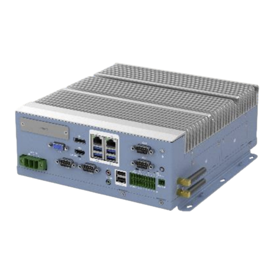
- Page 22 KMDA-7920-S001 Side Panel: Figure 2.6 I/O ports on the side panel: ⚫ 2*SATA SSD/HDD ⚫ 2*ANT KMDA-7610-S001 front view: Figure 2.7 I/O ports on the front panel: ⚫ 1*DC-in Power jack: 3-pole Phoenix terminal block ⚫ 1*Remote SW: 2-pole terminal block ⚫...
-
Page 23: Ethernet Port(Lan
User’s Manual ⚫ Power button ⚫ HDD LED, CPU LEDs ⚫ AT/ATX SW, Clear CMOS SW KMDA-7610-S001 Side Panel: Figure 2.8 I/O ports on the side panel: ⚫ 2*SATA SSD/HDD ⚫ 2*ANT 2.3.1 Ethernet port(LAN) The KMDA-7921/7920/7610 is equipped with 1*Intel® I226V network chip and 1*Intel® I219LM network chip, providing two Gigabit network ports and supporting 10/100/1000Mbps rate adaptive. -
Page 24: Usb Interface
User’s Manual 2.3.2 USB Interface The KMDA-7921/7920/7610 supports 6*USB ports, including 4*USB3.2 and 2*USB2.0. These USB interface connectors support plug-and-play and hot-swappable capabilities and can be disabled through system BIOS settings. Table 2.2 provides a detailed description of pin assignment for USB2.0. Figure 2.10 USB2.0 Table 2.2: USB2.0 Port Pin Assignments... -
Page 25: Hdmi
User’s Manual 2.3.3 HDMI The KMDA-7921/7920/7610 provides a high resolution HDMI display interface with a maximum resolution of 4096*2160@60Hz. Table 2.4 describes the detailed pin assignment. Figure 2.12 HDMI Table 2.4: HDMI Port Pin Assignments Signal Signal Signal DATA2_P DATA0_N DATA2_N CLK_P DATA1_P... -
Page 26: Vga
User’s Manual 2.3.5 VGA The KMDA-7921/7920/7610 provides a standard VGA interface that supports a maximum resolution of 1920*1200@60Hz. Table 2.6 provides detailed pin assignment. Figure 2.14 VGA Table 2.6: VGA Port Pin Assignments Signal Signal GREEN BLUE 2.3.6 COM1/2/3/4 Port The KMDA-7921/7920/7610 provides 2*COM interface (COM1/2) through a dual-layer DB9, and RS232/422/485 mode can be set through the BIOS, and provides 2*RS232 serial port (COM3/4) through two single-row DB9 ports. -
Page 27: Dio Port
User’s Manual Figure 2.16 COM3/4 Table 2.8: COM3/COM4 Port Pin Assignments Signal Signal COM_DCD COM_SIN3 COM_SOUT COM_DTR COM_DSR COM_RTS COM_CTS COM_RI 2.3.7 DIO Port KMDA-7921/7920/7610 provides 16-bit isolated DIO through one 2*10Pin connector. Table 2.9 provides a detailed description of pin assignments. Figure 2.17 DIO Table 2.9: DIO Port Pin Assignments... -
Page 28: Sata Port
User’s Manual DOUT5 DOUT6 DOUT7 ECOM1 E_GND VCC_ISO PCOM1 2.3.8 SATA Port The KMDA-7921/7920/7610 provides two standard SATA3.0 interfaces with data transfer rates up to 6Gb/s for connecting SATA devices. Table 2.10 provides a detailed description of pin assignments. Figure 2.18 SATA Table 2.10: SATA Port Pin Assignments Signal... -
Page 29: Mini Pcie
User’s Manual shown in Table 2.12. Figure 2.20 Remote SW Table 2.12: Remote Switch Signal Interface Pin Assignments Signal PWR_BTN 2.3.11 Mini PCIe KMDA-7921/7920/7610 provides a standard full size Mini PCIe interface with PCIeX1 and USB2.0 signals, SIM card slot, and can install functional module cards such as 4G cards, network cards, and serial cards that comply with the Mini PCIe specification. -
Page 30: Led Light
Figure 2.22 2.3.13 Power Interface (DC-IN) The KMDA-7610/7920/7921 provides a wide voltage (9~36V) input via a 3-pin 7.62mm pitch terminal. Table 2.14 provides a detailed description of pin assignments.. - Page 31 User’s Manual Figure 2.23 DC IN Table 2.14: DC-IN Port Pin Assignments Signal Signal 9~36V...
-
Page 32: Installation
User’s Manual 2.4 Installation The KMDA-7921 is used as an example for hardware installation. The KMDA-7920/7610 series is similar. 2.4.1 HDD/SSD Install Step 1: Unscrew the four screws on the disk cover and remove the disk cover. Figure 2.24 Step 2: Unscrew the two screws on the hard disk tray and remove the hard disk tray. Figure 2.25 Step 3: Install the HDD or SSD in the hard disk tray, tighten the four screws to secure them. - Page 33 User’s Manual Figure 2.26 Figure 2.27 Step 4: Insert the hard disk and the hard disk tray into the hard disk slot, as shown in the figure. Figure 2.28 Step 5: Tighten one screw to secure the hard disk and the hard disk tray.
-
Page 34: Mini Pcie/Msata Module Install
User’s Manual Figure 2.29 Step 6: Install the hard disk cover and tighten the 4 screws. 2.4.2 Mini PCIe/mSATA Module Install (KMDA-7921/7920): Step 1: Loosen the screws shown in the figure and remove the expansion cover. Figure 2.30 Figure 2.31... - Page 35 User’s Manual Step 2: Unscrew the 6 screws on the expansion box and remove the expansion box. Figure 2.32 Figure 2.33...
- Page 36 Figure 2.34 Step 4: Complete the installation of the machine with the reverse steps. (KMDA-7610): Step 1: Unscrew the 7 screws on the bottom cover (4 at the front and back, 3 at the side) as shown in the figure and remove the bottom shell.
- Page 37 User’s Manual Figure 2.36 Step 2: Hold the Mini PCIe/mSATA module so that its slot aligns with the Mini PCIe/mSATA slot on the motherboard, insert it into the socket at a 30 degree angle, and lock the screw to secure it. Figure 2.37 Step 3: Complete the installation of the machine with the reverse steps.
-
Page 38: Bios Setup
User’s Manual BIOS Setup... -
Page 39: Bios Description
User’s Manual 3.1 BIOS Description BIOS is the communication bridge between hardware and software. How to correctly set the BIOS parameters is crucial for the system to work stably and whether the system works at its best. This chapter describes how to change the system settings through the BIOS settings. Note: For the purpose of better product maintenance, the manufacture reserves the right to change the BIOS items presented in this manual. -
Page 40: Bios Parameter Settings
User’s Manual 3.2 BIOS parameter settings When you start the Setup Utility, the main menu appears. The main menu of the Setup Utility displays a list of the options that are available. A highlight indicates which option is currently selected. Use the cursor arrow keys to move the highlight to other options. -
Page 41: Bios Navigation Keys
User’s Manual 3.2.1 BIOS Navigation Keys Enter the SETUP settings interface, The BIOS navigation keys are listed below: Table 3.1: The BIOS navigation keys FUNCTION Exit the current menu ↑↓→← Scrolls through the items on a menu Change Opt. Enter Select General Help Previous Values... - Page 42 User’s Manual...
-
Page 43: Advanced Menu
User’s Manual BIOS Information This item shows the information of the BIOS vendor, version, build date and time etc. Board Information This item shows the basic information of the motherboard, including the Board ID and BIOS Version of the motherboard. Processor Information This item shows the basic information about the currently used processor, including name, type, speed, ID, core, Microcode version, etc. - Page 44 User’s Manual CPU Configuration The configuration of the central processor, enter this sub-menu, there will be detailed details of the CPU, as well as various settings of the CPU. Power & Performance Configuration This item contains the Power & Performance configuration, enter this sub-menu, there will be detailed details of the Power &...
- Page 45 User’s Manual Hardware Monitor...
-
Page 46: Chipset Menu
User’s Manual Hardware monitoring, enter this sub-menu, there will be CPU temperature, fan speed, status display of each common working voltage, as well as parameter settings of intelligent fan control. CSM Configuration CSM (Compatibility Support Module) configuration, enter this sub-menu, there will be various settings to support UEFI startup and non-UEFI startup. - Page 47 User’s Manual System Agent (SA) Configuration Memory Configuration Memory configuration, enter this submenu, there will be detailed memory information. Graphics Configuration Image processing configuration, enter this sub-menu, there will be CPU-integrated graphics related settings. PEG Port Configuration PEG graphics configuration, enter this sub-menu, there will be related settings for the external graphics card.
-
Page 48: Security Menu
User’s Manual 3.2.5 Security menu Administrator Password This item sets the information of the administrator password. User Password This item sets the information of the normal user password. Secure Boot This item sets the information of the secure boot.Secure Boot feature is Actice if Secure Boot is Enabled,Platform key(PK) is enrolled and mode change requires platform reset. - Page 49 User’s Manual...
-
Page 50: Boot Menu
User’s Manual 3.2.6 Boot menu Setup Prompt Timeout Setup prompts for waiting time. This option is to set the time to wait for the Del key to enter the BIOS setup after booting. Bootup NumLock State Set the state of the small numeric keypad at startup. Quiet Boot Switch full screen logo control. -
Page 51: Save & Exit Menu
User’s Manual 3.2.7 Save & Exit menu Save changes and Exit This item enables you to save the changes that you have made and exit. Discard Changes and Exit This item enables you to discard the changes that you have made and exit. Save Changes and Reset This item enables you to save the changes that you have made and reset. -
Page 52: Updating The Bios
User’s Manual This item enables you to restore the user defaults. 3.3 Updating the BIOS The BIOS (Basic Input and Output System) Setup Utility displays the system’s configuration status and provides you with options to set system parameters. The parameters are stored in battery-backed-up CMOS RAM that saves this information when the power is turned off. -
Page 53: Driver Installation
User’s Manual Driver Installation... -
Page 54: Follow The Sequence Below To Install The Drivers
User’s Manual The KMDA-7921/7920/7610 comes with a CD-ROM that contains all drivers and utilities that meet your needs. 4.1 Follow the sequence below to install the drivers: Figure 4.1 Step 1 – Install Audio Driver Step 2 – Install Chipset Driver Step 3 –... -
Page 55: Utility Software Reference
User’s Manual 4.3 Utility Software Reference All the utility software available from this page is Windows compliant. They are provided only for the convenience of the customer. The following software is furnished under license and may only be used or copied in accordance with the terms of the license.
Need help?
Do you have a question about the KMDA-7610 and is the answer not in the manual?
Questions and answers