Table of Contents
Advertisement
Quick Links
User's Manual
User's Manual
PMI-3110
PMI-3110
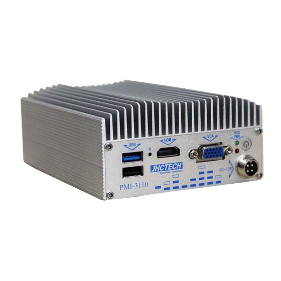
1, Aluminum case , Fanless disign;
2, Intel® Celeron® J1900;
3, 1xDDR3L-1333 DIMM, max 8GB;
4, 1xmSATA, 1x2.5inch HDD;
5, 1xminipcie with SIM card support 3G/LTE;
6, DC 12V input;
7, VGA&HDMI display;
8, 2COM/2USB/Audio;
9, 2× Intel I210IT Gigabit Ethernet ;
10, HDD Anti-vibration design。
Ver, A1.2
Date,23rd,Nov.,2015
1
Advertisement
Table of Contents

Related Manuals for JHCTech PMI-3110


Summary of Contents for JHCTech PMI-3110
- Page 1 User’s Manual User’s Manual PMI-3110 PMI-3110 1, Aluminum case , Fanless disign; 2, Intel® Celeron® J1900; 3, 1xDDR3L-1333 DIMM, max 8GB; 4, 1xmSATA, 1x2.5inch HDD; 5, 1xminipcie with SIM card support 3G/LTE; 6, DC 12V input; 7, VGA&HDMI display; 8, 2COM/2USB/Audio;...
- Page 2 User’s Manual Version Note Ver. Note Date Writer A1.0 first publish 20150510 Jie Deng A1.1 Add installation 20150723 Wei Li A1.2 Revise the max memory capacity 20151123 Wei Li...
- Page 3 User’s Manual Copyright The documentation and the software included with this product are copy- righted 2006 by ShenZhen JHC Technology Co., Ltd. All rights are reserved. ShenZhen JHC Technology Co., Ltd. reserves the right to make improvements in the products described in this manual at any time without notice. No part of this manual may be reproduced, copied, translated or transmitted in any form or by any means without the prior written permission of ShenZhen JHC Technology Co., Ltd.
- Page 4 User’s Manual Product Warranty (2 years) JHC warrants to you, the original purchaser, that each of its products will be free from defects in materials and workmanship for two years from the date of purchase. This warranty does not apply to any products which have been repaired or altered by persons other than repair personnel authorized by JHC, or which have been subject to misuse, abuse, accident or improper installation.
-
Page 5: Declaration Of Conformity
User’s Manual Declaration of Conformity This product has passed the CE test for environmental specifications when shielded cables are used for external wiring. We recommend the use of shielded cables. This kind of cable is available from JHC. Please contact your local supplier for ordering information. Test conditions for passing included the equipment being operated within an industrial enclosure. -
Page 6: Table Of Contents
2.4.3 USB 2.0 Connector ........................11 2.4.4 COM1 Connector ........................12 2.4.5 COM2 Connector ........................12 2.5 Installation ............................13 2.5.1 HDD/SSD Installation (Only for PMI-3110-S002) ..............13 2.5.2 Memory chip Installation ......................14 2.5.3 MSATA / MINIPCIE(3G/WIFI) Installation ................ 15 BIOS Setup ........................16 3.1 BIOS Setup ............................ - Page 7 User’s Manual 3.5.1 North Bridge ..........................25 3.5.2 Intel IGD Configuration ......................25 3.5.3 South Bridge ..........................26 3.6 Security Setup ............................. 27 3.7 Boot Settings ............................28 3.8 Save & Exit ............................29 3.8.1 Save Changes and Exit ......................29 3.8.2 Discard Changes and Exit ......................
-
Page 8: General Information
User’s Manual General Information... -
Page 9: Introduction
I/O interface and 2.5inch HDD driver bay. PMI-3110 offers 1xVGA, 1xHDMI interface, 2xGiga Lan ports, 1xUSB3.0 ports, 1xUSB2.0 ports, Audio,2xCOM ports, 1xMini PCIe socket with SIM holder; The PMI-3110 supports 2.5inch SATA HDD driver bay, 1xmSATA for storage options. -
Page 10: Display
Vibration loading during operation: – With SSD/mSATA: 3 Grms, IEC 60068-2-64, random, 5 ~ 500 Hz, 1 hr/axis Shock during operation: – With SSD/mSATA: 30 G, IEC 60068-2-64, half sine, 11 ms duration EMC: CE, FCC Class A 1.5 Mechanical Specifications PMI-3110-S001 Dimensions:... - Page 11 User’s Manual PMI-3110-S002 Dimensions: Figure 1.1...
-
Page 12: Hardware Installation
User’s Manual Hardware Installation... -
Page 13: Introduction
2.2.1 Setting Jumpers You can configure your PMI-3110 to match the needs of your application by setting the jumpers. A jumper is the simplest kind of electrical switch. It consists of two metal pins and a small metal clip (often protected by a plastic cover) that slides over the pins to connect them. - Page 14 User’s Manual Figure 2.3...
-
Page 15: Pwron_Sel1
User’s Manual Jumpers Jumper Name Description PWRON_SEL1 Auto Power-ON Select 3-Pin Block COM1_PWR1 COM1 RS232/power select 6-Pin Block COM1 RS232/485 select COM1_SEL1 3-Pin Block COM1_SEL 3-Pin Block COM3_SEL COM3 RS422/485 Select 3-Pin Block 2.3.1 PWRON_SEL1 PWRON_SEL1 is used to select the method of powering on the system. If you want the system to power-on whenever AC power comes in, set PWRON_SEL1 pins 2 and 3 to On. -
Page 16: Com1_Sel
User’s Manual 2.3.4 COM1_SEL COM1_SEL are used to configure the Serial COM ports to RS232 or RS485. Figure 2.7 Pins Function RS485_SIN1 SIN1 SSIN1 Note:when COM1_SEL selected,COM1_SEL1 must be set in accordance to COM1_SEL1 2.3.5 COM3_SEL COM3_SEL are used to configure the Serial COM port to RS232 or RS485. Figure 2.8 Pins Function... -
Page 17: Ethernet Connector (Lan)
S002: 2.4.1 Ethernet Connector (LAN) The PMI-3110 is equipped with two Intel WGI211 for 10/100/1000Mbps Ethernet controllers. The Ethernet port provides a standard RJ-45 jack connector with LED indicators on the front side to show its Active/Link status (Green LED) and Speed status (white LED). Table 2.2 for pin assignments... -
Page 18: Power Input Connector (Dc-In)
BI_DD-(GHz) Note: NC represents —No Connection“ 2.4.2 Power Input Connector (DC-IN) The PMI-3110 comes with a 4-pole DIN-jack that 12V~24V external power input. Please refer to Table 2.3 for their pin assignments. Figure 2.11 4-pole DC DIN-Jack Table 2.3: Power Connector Pin Assignments... -
Page 19: Com1 Connector
6 7 8 9 Figure 2.13 COM3/COM4Connector RS-232 RS-485 Signal Name Signal Name DATA- DATA+ Note: NC represents —No Connection“ 2.4.5 COM2 Connector The PMI-3110 provides a RS-232 ports by a D-sub 9-pin connectors. Please refer to Table 2.6 for their pin assignments. -
Page 20: Installation
6 7 8 9 Figure 2.14 COM1/2/5/6 Connector Table 2.6: COM1/2/5/6 Serial Port Pin Assignments Signal Name 2.5 Installation 2.5.1 HDD/SSD Installation (Only for PMI-3110-S002) a) Use the cross screwdriver,demount the screws on bottom cover as below: Figure 2.15 Figure 2.16... -
Page 21: Memory Chip Installation
User’s Manual b) Fix the hard disk drive on the mounting bracket with 4 cross round screws(M3×4mm) ,insert 4 shockproof rubber rings into the mounting bracket hole , and paste one hard disk heat conduction paste on the hard disk drive as below: Thick:1.5mm Figure 2.17 Figure 2.18... -
Page 22: Msata / Minipcie(3G/Wifi) Installation
User’s Manual Figure 2.21 Figure 2.22 2.5.3 MSATA / MINIPCIE(3G/WIFI) Installation a) Take a MSATA/MINIPCIE, insert it into the main board as below MSATA MINIPCIE(3G/WI position FI) position Figure 2.23 Figure 2.24 b) Use the cross screwdriver to fix the bottom cover as shown in figure. Notice: Pay attention to the direction of bottom cover. -
Page 23: Bios Setup
User’s Manual BIOS Setup... -
Page 24: Bios Setup
AMIBIOS has been integrated into many motherboards for over a decade. With the AMIBIOS setup program, you can modify BIOS settings and control the various system features. This chapter describes the basic navigation of the PMI-3110 BIOS setup screens. Figure 3.1 Setup program initial screen AMI's BIOS ROM has a built-in Setup program that allows users to modify the basic system onfiguration. -
Page 25: System Date / System Time
3.4 Advanced BIOS Features Setup Select the Advanced tab from the PMI-3110 setup screen to enter the Advanced BIOS Setup screen. You can select any of the items in the left frame of the screen,such as CPU Configuration, to go to the sub enu for that item. -
Page 26: It8783 Super I/O Configuration
User’s Manual Figure 3.3 Advanced BIOS features setup screen 3.4.1 IT8783 Super I/O Configuration Figure 3.4 Super IO Configuration Serial Port 1 Configuration:This item allows users to configure serial port 1. Serial Port 2 Configuration:This item allows users to configure serial port 2. Serial Port 3 Configuration:This item allows users to configure serial port 3. -
Page 27: Hardware Monitor
User’s Manual 3.4.2 Hardware Monitor Figure 3.5 hardware monitor This page display all information about system Temperature/Voltage. 3.4.3 CPU Configuration Figure 3.6 CPU Configuration Limit CPUID Maximum Disabled for Windows XP. Execute Disable Bit XD can prevent certain classes of malicious buffer overflow attacks when combined with a supporting OS... -
Page 28: Ide Configuration
User’s Manual (Windows Server 2003 SP1, Windows XP SP2,SuSE Linux 9.2, RedHat Enterprise 3 Update 3.) Intel Virtualization Technology When enabled, a VMM can utilize the additional hardware capabilities provided by Vanderpool Technology. Power Technology Enable the power management features. 3.4.4 IDE Configuration Serial-ATA (SATA) Enable / Disable Serial ATA. -
Page 29: Csm Configuration
User’s Manual Figure 3.8 Miscellaneous Configuration 3.4.6 CSM Configuration Figure 3.9 CSM Configuration CSM Support Enable/Disable CSM Support. -
Page 30: Usb Configuration
User’s Manual GateA20 Active UPON REQUEST - GA20 can be disabled using BIOS services. ALWAYS do not allow disabling GA20; this option is useful when any RT code is executed above 1MB. Option ROM Messages Set display mode for Option ROM. INT19 Trap Response BIOS reaction on INT19 trapping by Option ROM: IMMEDIATE - execute the trap right away;... -
Page 31: Chipset Configuration
DISABLE option will keep USB devices available only for EFI applications. 3.5 Chipset Configuration Select the Chipset tab from the PMI-3110 setup screen to enter the Chipset BIOS Setup screen. You can display a Chipset BIOS Setup option by highlighting it using the <Arrow> keys. All Plug and Play BIOS Setup options are described in this section. -
Page 32: North Bridge
User’s Manual 3.5.1 North Bridge Figure 3.12 North Bridge Intel IGD Configuration:Config Intel IGD Settings. TOLUD:Maximum Value of TOLUD. 3.5.2 Intel IGD Configuration Figure 3.13 Intel IGD Configuration... -
Page 33: South Bridge
User’s Manual Boost:Enable/Disable GPU Boost acceleration. PAVC:Audio, video, protect control switch, enable this technology, audio and video in the whole process of transmission and broadcast in the protected state.Note that if you play blu-ray disc, this item must be enabled. DVMT Pre-Allocated:Select DVMT 5.0 Pre-Allocated (Fixed) Graphics Memory size used by the Internal Graphics Device. -
Page 34: Security Setup
3.6 Security Setup Figure 3.15 Security Setup Select Security Setup from the PMI-3110 Setup main BIOS setup menu. All Security Setup options, such as password protection is described in this section. To access the sub menu for the following items, select the item and press <Enter>. -
Page 35: Boot Settings
User’s Manual 3.7 Boot Settings Figure 3.16 Boot Setup Utility Setup Prompt Timeout:This item allows users to select the number of seconds to wait for setup activation key. Bootup NumLock State:Select the Power-on state for Numlock. Quiet Boot:If this option is set to Disabled, the BIOS displays normal POST messages. If Enabled, an OEM Logo is shown instead of POST messages. -
Page 36: Save & Exit
User’s Manual 3.8 Save & Exit Figure 3.17 Save & Exit 3.8.1 Save Changes and Exit When users have completed system configuration, select this option to save changes, exit BIOS setup menu and reboot the computer if necessary to take effect of all system configuration parameters. 3.8.2 Discard Changes and Exit Select this option to quit Setup without making any permanent changes to the system configuration. -
Page 37: Discard Changes
Select this option to discard any current changes and load previous system configuration. 3.8.7 Restore Defaults The PMI-3110 automatically configures all setup items to optimal settings when users select this option. Optimal Defaults are designed for maximum system performance, but may not work best for all computer applications. -
Page 38: Driver Installation
User’s Manual Installation Driver... -
Page 39: Follow The Sequence Below To Install The Drivers
Please read instructions below for further detailed installations. 4.2 Installation: Insert the PMI-3110 CD-ROM into the CD-ROM drive. And install the drivers from Step 1 to Step 4 in order. Step 1 – Install Chipset Driver 1)Click on the Step 1 - Intel Chipset Software Installation Utility folder and double click on the infinst_autol.exe...
Need help?
Do you have a question about the PMI-3110 and is the answer not in the manual?
Questions and answers