Table of Contents
Advertisement
Quick Links
Advertisement
Table of Contents

Related Manuals for Dnake B17-EX003/S

Summary of Contents for Dnake B17-EX003/S
- Page 1 User Manual ——— DNAKE Expansion Module...
- Page 3 REMARK Please follow the user manual for correct installation and testing. If there is any doubt please call our tech-supporting and customer center. Our company applies ourselves to reformation and innovation of our products. No extra notice for any change. The illustration shown here is only for reference. If there is any difference, please take the actual product as the standard.
-
Page 4: Table Of Contents
CATALOG PRODUCT FEATURE ..........1 TECHNICAL PARAMETER ........1 PACKAGE CONTENT ..........2 OVERVIEW .............. 1 BASIC SETTING ............3 SYSTEM DIAGRAM ..........5 DEVICE WIRING ............. 6 INSTALLATION ............7 SAFETY INSTRUCTION ........13 FCC Warning ............14... -
Page 5: Product Feature
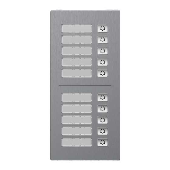
1. High quality, IK07, IP 65 2. 10 Metal buttons (B17-EX001/S) 5 Metal buttons, 1 Nameplate Area (B17-EX002/S) 2 Nameplate Area (B17-EX003/S) 3. Nameplate and buttons with backlight (B17-EX001/S & B17-EX002/S) Nameplate with backlight (B17-EX003/S) 4. Support surface and flush installation... -
Page 6: Package Content
PACKAGE CONTENT MODEL: B17-EX001/S, or B17-EX002/S, or B17-EX003/S, Sealing Plug of Module Wiring Cover Junction Pressing PM2.5×6 (4 pcs) Wiring Port Screw Fixing Seat Rear Cover PA4×30 (2 pcs) PM4×20 (2 pcs) FM3×4.5 (2 pcs) (2 pcs) Wrench Screw Wires... -
Page 7: Overview
OVERVIEW Model: B17-EX001/S Model: B17-EX002/S... - Page 8 Model: B17-EX003/S...
-
Page 9: Basic Setting
(admin) and password (123456). This is where you can configure the device. For getting the IP address, you can search by DNAKE Remote Upgrade Tool which is installed in the same LAN with the devices. 1. Basic configuration Follow the instructions below to configure the module: Step 1: Connect RS485 ports to door station and set the binary number nearby. - Page 10 Step 4: Go to Advanced > Module. If persons are added, residents can be selected and room number will be filled in accordingly and locked. Room number can still be filled in without any resident.
-
Page 11: System Diagram
SYSTEM DIAGRAM... -
Page 12: Device Wiring
DEVICE WIRING 1. 485 IN Connect the module to the door station or the previous module via RS485 ports. Connect the power adapter to the module. 2. 485 OUT Connect the module to the next expansion module. 3. DIP Switch Set the module number from 00 to 15. -
Page 13: Installation
INSTALLATION Installation of Wiring Cover... - Page 14 Surface Mounting-86 Mounting Box Product size: 88 × 188 × 32.5 mm Surface Mounting size: 88 × 188 × 34...
- Page 15 Surface Mounting-118 Mounting Box Product size: 88 × 188 × 32.5 mm Surface Mounting size: 88 × 188 × 34...
- Page 16 Flush Mounting (Accessories required) Product size: 88 × 188 × 32.5 mm Flush Mounting size: 120 × 230 × 48 Hole-cutting size: 98 × 219 × 42...
- Page 17 Flush Mounting (Accessories required) Product size: 88 × 188 × 32.5 mm Flush Mounting size: 120 × 230 × 48 Hole-cutting size: 195 × 219 × 42...
- Page 18 Flush Mounting (Accessories required) Product size: 88 × 188 × 32.5 mm Flush Mounting size: 120 × 230 × 48 Hole-cutting size: 291 × 219 × 42 Tips: The camera should be 1450~1550mm above the ground. The camera at this height can capture human face perfectly.
-
Page 19: Safety Instruction
SAFETY INSTRUCTION In order to protect you and others from harm or your device from damage, please read the following information before using the device. Do not install the device in the following places: Do not install the device in high-temperature and moist environment or the area close to ... -
Page 20: Fcc Warning
FCC Warning This device complies with Part 15 of the FCC Rules. Operation is subject to the following two conditions: (1) This device may not cause harmful interference, and (2) this device must accept any interference received, including interference that may cause undesired operation. - Page 21 RF exposure statement This equipment complies with the FCC radiation exposure limits set forth for an uncontrolled environment. This transmitter must not be co-located or operating in conjunction with any other antenna or transmitter.
- Page 22 V1.1 EASY SMART INTERCOM SOLUTIONS...
Need help?
Do you have a question about the B17-EX003/S and is the answer not in the manual?
Questions and answers