Advertisement
Quick Links
Advertisement

Related Manuals for Dnake B17-EX001/S

Summary of Contents for Dnake B17-EX001/S
- Page 1 EXPANSION MODULE МОDEL: B17-EX001/S B17-EX002/S B17-EX003/S QUICK START GUIDE...
- Page 2 REMARK Please follow the user manual for correct installation and testing. If there is any doubt please call our tech-supporting and customer center. Our company applies ourselves to reformation and innovation of our products. No extra notice for any change. The illustration shown here is only for reference.
- Page 3 CATALOG Package Contents ....................1 Pictures ........................2 System Configuration ..................4 System Diagram ....................5 Installation ........................6 Safety Instructions ....................10 FCC Warning ......................11...
- Page 4 PACKAGE CONTENTS Please make sure the package contains the following items: MODEL: B17-EX001/S Sealing Plug of Junction Expansion Module Wiring Port Pressing Plate Rear Cover Screw Fixing Seat Wrench Wiring Cover Screw EXPANSION MODULE МОDEL: B17-EX001/S B17-EX002/S B17-EX003/S QUICK START GUIDE...
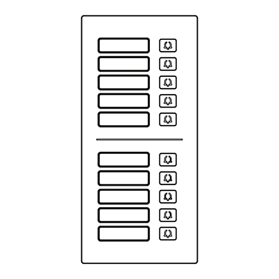
- Page 5 Sealing Plug of Junction Expansion Module Rear Cover Wiring Port Pressing Plate Screw Fixing Seat Wrench Wiring Cover Screw EXPANSION MODULE МОDEL: B17-EX001/S B17-EX002/S B17-EX003/S QUICK START GUIDE Quick Start Guide Wires PICTURES MODEL: B17-EX001/S Nameplate/ Call button Room No.
- Page 6 MODEL: B17-EX002/S Call button Nameplate/ Room No. MODEL: B17-EX003/S Nameplate/ Room No.
- Page 7 SYSTEM CONFIGURATION Villa Alarm Sensors Indoor Monitor Smart Life APP 6 Max Power Supply Lock RS485 IP Camera PoE Switch Expansion Villa Module Station RVV2*0.5 16 Max CAT-5e Internet...
- Page 8 SYSTEM DIAGRAM 1. 485 IN Connect the module to the door station or the previous module via ● RS485 ports. Connect the power adapter to the module. ● 2. 485 OUT Connect the module to the next expansion module. 3. DIP Switch Set the module number from 00 to 15.
- Page 9 INSTALLATION MODEL: B17-EX001/S, B17-EX002/S, B17-EX003/S (Installation of Wiring Cover) Wiring Cover Expansion Wiring Cover Module Plug Junction Screw Pressing Plate...
- Page 10 MODEL: B17-EX001/S, B17-EX002/S, B17-EX003/S (Surface Mounting-86 Mounting Box) Mounting Box Screws Screws Bracket Product size: 88x188x32.5mm...
- Page 11 MODEL: B17-EX001/S, B17-EX002/S, B17-EX003/S (Surface Mounting-118 Mounting Box) Mounting Box Screws Screws Bracket Product size: 88x188x32.5mm...
- Page 12 MODEL: B17-EX001/S, B17-EX002/S, B17-EX003/S (Flush Mounting) Expansion Module Expansion Module...
- Page 13 SAFETY INSTRUCTIONS In order to protect you and others from harm or your device from damage, please read the following information before using the device. Do not install the device in the following places: Do not install the device in high-temperature and moist environment or ●...
- Page 14 FCC WARNING This device complies with Part 15 of the FCC Rules. Operation is subject to the following two conditions: (1) This device may not cause harmful interference, and (2) this device must accept any interference received, including interference that may cause undesired operation.
- Page 16 V1.0 600110187400...
Need help?
Do you have a question about the B17-EX001/S and is the answer not in the manual?
Questions and answers