
Related Manuals for Antec Scientific DECADE II

Summary of Contents for Antec Scientific DECADE II
- Page 1 Antec Scientific Industrieweg 12 2382 NV Zoeterwoude The Netherlands DECADE II Electrochemical Detector Service manual 171.0020, Edition 4, 2010 T +31 71 5813333 | info@AntecScientific.com | https://AntecScientific.com...
- Page 2 DECADE II service manual, edition 4...
- Page 3 INTRODUCTION...
- Page 4 The information contained in this document is subject to change without notice. ROXY Potentiostat, DECADE II, DECADE, INTRO, Sencell, Flexcell, Reactor, ISAAC, HyREF, LINK, ADF, DECADE Dialogue, ROXY Potentiostat Dialogue are trademarks of Antec Leyden BV. Whatman™ (word and device) and Whatman™...
- Page 5 INTRODUCTION Declaration of conformity Antec Leyden B.V., The Netherlands declares that the product DECADE II™ Electrochemical Detector (p.n. 171.0035) to which this declaration relates, is in conformity with the following directives: Safety (73/23/EEC) Safety requirements for laboratory EN61010-1:2001 equipment (Class I, Installation cat. II, Pollution degree 2)
- Page 6 DECADE II service manual, edition 4 EN55011 (Class B), EN61000-3-2, EN61000-3-3 Attention Only use manufacturer-supplied cable(s) to connect with other devices. Part numbers 250.0122 (RS232 cable), 250.0130 (I/O cable) and 250.0128 (output cable). Thoroughly connect shielding to common. Manufacturer will not accept any liability for damage, direct or indirect, caused by connecting this instrument to devices which do not meet relevant safety standards.
-
Page 7: Symbols
Symbols The following symbol are used on the rear panel and oven compartment of the DECADE II: Consult the manual for further safety instructions Frame or chassis ground terminal The following pictograms are used in the DECADE II manual: Caution... - Page 8 DECADE II service manual, edition 4 Caution, risk of electric shock or other electrical hazard (high voltage)
-
Page 9: Safety Practices
INTRODUCTION Safety practices The following safety practices are intended to insure safe operation of the equipment. Electrical hazards The removal of protective panels on the instrument can result in exposure to potentially dangerous voltages. Therefore, disconnect the instrument from all power sources before disassembly. Untrained personnel should not open the instrument. -
Page 10: Spare Parts And Service Availability
DECADE II service manual, edition 4 Connect the detector to a grounded AC power source, line voltage 100 – 240 VAC. The instrument should be connected to a protective earth via a ground socket. The power source should exhibit minimal power transients and fluctuations. - Page 11 INTRODUCTION Copyright ©2010. All rights reserved. Contents of this publication may not be reproduced in any form or by any means (including electronic storage and retrieval or translation into a foreign language) without prior agreement and written consent from the copyright of the owner. The information contained in this document is subject to change without notice.
-
Page 12: Table Of Contents
DECADE II service manual, edition 4 Table of contents Symbols 7 Safety practices 9 Spare parts and service availability 10 Required service tools 14 Replacement of EPROMS 15 Introduction 15 Removing the connector panel 16 Location of EPROM on sensor board 19... -
Page 13: Introduction
INTRODUCTION ECELL Cell potential 42 TEMP Temperature calibration (FW version 2.05) 43 TEMP Temperature calibration (FW version 3.xx) 45 Key combinations 47 Reset to factory defaults 47 Enter service mode 47 Erase time files 47 Configuration of dip switches 49... -
Page 14: Required Service Tools
DECADE II service manual, edition 4 C H A P T E R Required service tools The following tools are necessary for servicing the DECADE II: [a] IC-puller or normal screwdriver [b] Socket wrench 3/16” [c] Phillips screwdriver Fig. 1. IC-puller, screwdriver, socket wrench and Phillips screwdriver (from left to right). -
Page 15: Replacement Of Eproms
Replacement of EPROMS Introduction The DECADE II is equipped with two circuit boards, a sensor board and a control board. Both boards are equipped with an EPROM in which the embedded software (firmware, FW) is stored necessary for boot-up of the detector. -
Page 16: Removing The Connector Panel
M3 Phillips screws as depicted in Fig. 3. The screws are marked in this picture with red arrows and the letters A and B. Fig. 3. Connector panel of the DECADE II 1. Remove the two screws located below (A) completely by means of a Phillips screwdriver. - Page 17 CHAPTER 2 Replacement of EPROMS picture in Fig. 3. Do not remove the two screws in the top part completely, but just loosen them a bit (a few turns). 2. Subsequently, pull the connector panel backwards as far as depicted in Fig. 4 (constrained by the length of the connected cables).
- Page 18 DECADE II service manual, edition 4...
-
Page 19: Location Of Eprom On Sensor Board
CHAPTER 2 Replacement of EPROMS Location of EPROM on sensor board Arrow (A) in Fig. 5 shows the location of the EPROM on the sensor board. Fig. 5. Top view sensor board. (A) sensor board EPROM, (B): internal cell cable connector and (C): I C/power cable connector. -
Page 20: Location Eprom On Control Board
DECADE II service manual, edition 4 Location EPROM on control board To access the EPROM on the control board it is necessary to remove the sensor board completely. This is done in the following manner: 1. Disconnect the internal cell cable depicted in Fig. 5 (B). This is a subD connector, which is fixed with two nuts. - Page 21 CHAPTER 2 Replacement of EPROMS Fig. 7. Removal of sensor board from the connector panel.
-
Page 22: Removing Eproms
DECADE II service manual, edition 4 Fig. 8. Top view of control board. (A) control board EPROM. Removing EPROMS Take precautions against electrostatic discharge during installation/removal of the EPROMS at all time. Both EPROMS can be removed from the board using an IC-puller or alternatively a flat screwdriver. -
Page 23: Recommended Tool
CHAPTER 2 Replacement of EPROMS After installation of the new EPROMS reassemble the detector and upload new flash firmware as described in chapter “Error! Reference source not found.”. RECOMMENDED TOOL: ALTERNATIVE: Fig. 9. Removing the EPROMS from the circuit boards. -
Page 24: Error Messages
DECADE II service manual, edition 4 C H A P T E R Error messages Table I. Error messages. Error Message Description Incompatible boot Boot software on control- and sensor version board are not the same revision. Install FW of same revision in both boards. - Page 25 CHAPTER 3 Error messages Error Message Description erase failed board. Hardware error. Try uploading firmware again, if not successful install another board. Contact supplier. Upload checksum Incorrect checksum. Try uploading error firmware again. If not successful, use another firmware file. Checksum error Incorrect checksum.
- Page 26 DECADE II service manual, edition 4 Error Message Description Contact supplier. Sensor board 5 SRAM read/write error during SRAM test. SRAM error Try again, if not successful replace board. Contact supplier. Sensor board 1 not No communication between sensorboard connect 1 and control board or sensor board 1 not detected.
- Page 27 CHAPTER 3 Error messages...
- Page 28 DECADE II service manual, edition 4...
-
Page 29: Service Menu
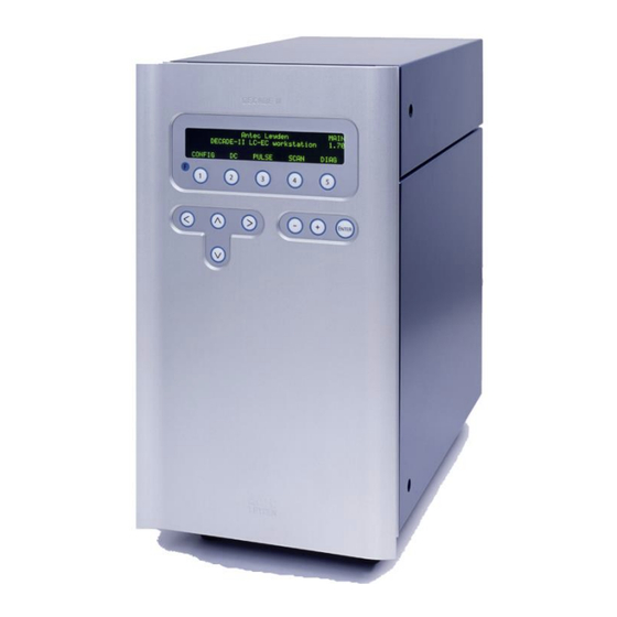
CHAPTER 4 Service menu C H A P T E R Service menu Main A n t e c L e y d e n M A I N D E C A D E - I I L C - E C w o r k s t a t i o n 2 . - Page 30 DECADE II service manual, edition 4 Parameter screen Description Type setting on the PC. Explanation: Type S is status, F is function and C is control.
-
Page 31: Test
CHAPTER 4 Service menu TEST T E S T 94 T e s t s P R E V M E M M E M 85 S R A M m e m o r y t e s t P R E V S T A R T I O 31... - Page 32 DECADE II service manual, edition 4 Parameter screen Description Type CB, SB1..6 Shows status of inputs Control Board and Sensor Board(s) (IN)ACT (in)activates outputs Explanation: Type S is status, F is function and C is control.
-
Page 33: Out
CHAPTER 4 Service menu Outputs can be set to active (press 2) or inactive (press 3). Testing outputs is done using the factory supplied connector cable and connecting the corresponding wire(s). Measure the output status with a calibrated voltmeter.: A. TTL outputs: connect the minus of the voltmeter to common and the plus of the voltmeter the TTL output that needs to be tested. - Page 34 DECADE II service manual, edition 4 Aux 1 0001 Aux 2 0010 1 - 2 Relay 1 (default) 0000 1 - 3 Relay 1 0100 4 - 5 Relay 2 (default) 0000 4 - 6 Relay 2 1000 “TF coding” refers to “0000” output string when editing a time file.
- Page 35 CHAPTER 4 Service menu Input status is reflected in display. If a short circuit with common is made the corresponding pin status will change to zero. Testing inputs is done using the factory supplied connector cable and connecting the corresponding wire(s). Table VI.
- Page 36 DECADE II service manual, edition 4 cell off 11011 reset 10111 cell on 01111 Default status is high (1).
-
Page 37: Adj
CHAPTER 4 Service menu A d j u s t m e n t s P R E V Z E R . I E O U T P E C E L L T E M P E c e l l = + 2 . 0 0 V E C E L L c l a m p g a i n... -
Page 38: Zer.ie Zero Current For Ie Converters
DECADE II service manual, edition 4 ZER.IE zero current for IE converters Before adjusting the zero current make sure the system has been stabilised for more than an hour with the cell off and T=35 C. Cell cable must be disconnected all the time. - Page 39 CHAPTER 4 Service menu Parameter Screen Description Type 100k, 1k Ohm ZER.IE Residual current ZER.IE Digital offset ADC Offs ZER.IE Analogue offset ADC AUTO ZER.IE Automatically compensate to zero current F UNDO ZER.IE Restore previous compensation setting RESET ZER.IE Release any zero compensation Explanation: Type S is status, F is function and C is control.
-
Page 40: Outp Output Voltage
DECADE II service manual, edition 4 OUTP Output voltage Before adjusting the output voltage make sure the system has been stabilised for more than an hour with the cell off and T=35 C. Cell cable must be disconnected all the time. - Page 41 CHAPTER 4 Service menu Parameter screen Description Type ZER.IE Select active resistor of IE converter using + or - button. Values are 100M, 10M, 1M, 100k, 1k Ohm ZER.IE Residual current ZER.IE Digital offset ADC Offs ZER.IE Analogue offset ADC AUTO ZER.IE Automatically compensate to zero current...
-
Page 42: Ecell Cell Potential
DECADE II service manual, edition 4 ECELL Cell potential Before adjusting the cell potential make sure the system has been stabilised for more than an hour with the cell off and T=35 Procedure: 1. Connect calibrated voltmeter to AUX & REF on (+) pole and WE on the other (-) pole. -
Page 43: Temp Temperature Calibration (Fw Version 2.05)
2000 ± 1 mV TEMP Temperature calibration (FW version 2.05) For DECADE II detectors with FW version 2.05 installed use the procedure below to perform a temperature calibration. This detectors have a SMT- 160 temperature sensor for temperature control. One can recognize the type of sensor which is active in the TEMP service screen. - Page 44 DECADE II service manual, edition 4 Fig. 11. Take out flow cell and place temperature sensor within white circle and close the door. Insert the temperature probe via the tubing hole (arrow) and close the door. 3. If temperature on external sensor differs from ‘measured temperature’...
-
Page 45: Temp Temperature Calibration (Fw Version 3.Xx)
P R E V C A L In case of upgrading a DECADE II FW 2.05 to FW 3.xx using one of the hardware upgrade kits mentioned in the table below, please consult the relevant temperature calibration instructions in the installation guides: 171.7034 or 171.7038 supplied with the kit. - Page 46 DECADE II service manual, edition 4 tubing holes in the top-left or top-right side of the oven (see white arrow in figure 11). 2. Press “CAL” button= (F2). By pressing the “CAL” button an auto- calibration routine will start. Internally the oven temperature is...
-
Page 47: Key Combinations
appendix 1 Key combinations A P P E N D I X Key combinations Reset to factory defaults In CONFIG screen press Enter button for 4 seconds. A message appears “RESET TO FACTORY SETTINGS?” If yes, factory settings will be loaded. - running time files or scans are stopped - reset of operational parameters (Ecell, range, filter, temperature…) Enter service mode... - Page 48 DECADE II service manual, edition 4...
-
Page 49: Configuration Of Dip Switches
A P P E N D I X Configuration of dip switches In order for the embedded software of the DECADE II to recognize all sensor boards properly the board address of the sensor boards should be set by means of the dip switches. The dip switches are located between the BNC connector and sub-D I/O connector at the edge of the board. - Page 50 DECADE II service manual, edition 4 Fig. 13. Dip switch settings for sensor board 2: 1-on, 2-off, 3-on and 4-on. Please place the transparent adhesive foil back after programming for protection. In the table below a complete overview is given for the settings of all 5 sensor boards: Sensor board ..1..2..3..4 (dip)
Need help?
Do you have a question about the DECADE II and is the answer not in the manual?
Questions and answers