
Related Manuals for Antec Scientific ROXY Exceed

Summary of Contents for Antec Scientific ROXY Exceed
- Page 1 Antec Scientific Industrieweg 12 2382 NV Zoeterwoude The Netherlands ROXY Exceed User Manual 211.0010, Edition 4, 2020 T +31 71 5813333 info@AntecScientific.com www.AntecScientific.com...
- Page 2 DECADE Elite, DECADE Lite, ROXY, ALEXYS, ROXY Exceed, INTRO, FlexCell, ReactorCell, µ-PrepCell, ISAAC, HyREF, SenCell and SynthesisCell are trademarks of Antec Scientific. Whatman™ (word and device) and Whatman™ (word only) are trademarks of Whatman international Ltd. SOLVENT IFD™ and AQUEOUS IFD™ are trademarks of Arbor Technologies, Inc.
- Page 3 Declaration of Conformity We Antec Leyden B.V., Zoeterwoude, The Netherlands, declare that the product: ROXY Exceed ™ Potentiostat type 211 to which this declaration relates, is in conformity with the following CE directives: 2014/35/EU Low Voltage Directive (LVD) 2014/30/EU Electromagnetic Compatibility Directive (EMC)
-
Page 4: Table Of Contents
211_0010 - ROXY Exceed user manual - rev 04 Table of contents Symbols 7 Intended use 9 WEEE directive 10 ROHS directive 10 Safety instructions 11 Introduction 15 Instrument description 16 Installation 19 Storage requirements 19 Site Preparation Requirements 19... -
Page 5: Chapter 1 Table Of Contents
CHAPTER 1 Table of contents Digital I/O connector 103 Chassis grounding stud 110 Troubleshooting 113 Instrument errors 113 Dummy cell test 115 Potentiostat accessories 121 Index 124... - Page 6 211_0010 - ROXY Exceed user manual - rev 04...
-
Page 7: Symbols
CHAPTER 1 Table of contents Symbols The following symbols might be used in this guide or may be found on the instrument: This sign warns about the risk of electric shock. It calls attention to a procedure or practice which, if not adhered to, could result in loss of life by electrocution. - Page 8 211_0010 - ROXY Exceed user manual - rev 04 The hot surface sign calls attention to parts in the instrument that must not be touched, as they may cause burns. This symbol indicates electrostatic discharge (ECD haz- ard), damages to system, device, or components can oc- cur if not properly grounded.
-
Page 9: Intended Use
CHAPTER 1 Table of contents Intended use The ROXY potentiostat in combination with flow-through reactor (µ- PrepCell or ReactorCell) or batch reactor cells (SynthesisCell) is used for controlled REDOX reactions up-front Mass Spectrometric detection. It can be used in a wide range of applications, for example: •... -
Page 10: Weee Directive
In case of questions, or if further information is required about the collec- tion & recycling procedure, please contact your local distributor. ROHS directive The ROXY Exceed is ROHS compliant and in conformity with Directive EU 2015/863 Restricted use of Hazardous Substances in electrical and elec- tronic Equipment (ROHS). -
Page 11: Safety Instructions
Table of contents Safety instructions Adhere to the following standard quality control procedures and the follow- ing equipment guidelines when using the ROXY Exceed potentiostat. The following safety practices are intended to ensure safe operation of the in- strument. Working environment & safety... - Page 12 AC power source, line voltage 100 – 240 VAC. The in- strument should be connected to a protective earth via a ground socket. The ROXY Exceed must only be used with appliances and power sources with proper protective grounding to prevent damage through build-up of static electricity.
- Page 13 Always wear protective And gloves when handling toxic or biologically infectious samples to pre- vent bio hazards or hazards while working with the ROXY Exceed. If ap- plicable the instrument must be decontaminated before decommis- sioning or shipment of the instrument for repair to Antec or its repre- sentatives.
- Page 14 211_0010 - ROXY Exceed user manual - rev 04...
-
Page 15: Introduction
CHAPTER 1 Introduction C H A P T E R Introduction Congratulations on your purchase of the ROXY Potentiostat. With more than 25 years of experience in Electrochemistry (EC), Antec introduces a new, dedicated Potentiostat for on-line EC/MS and EC/LC/MS. The ROXY Potentiostat generates metabolites of drugs or xenobiotics, similar to those generated during in vivo metabolic processes, in a significantly shorter time span (seconds vs. -
Page 16: Instrument Description
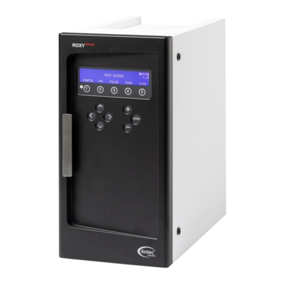
211_0010 - ROXY Exceed user manual - rev 04 Instrument description ROXY Exceed – Front side Description Description Instrument housing '+' and '-' value keys LC tubing inlet/outlet Cursor keys Instrument door panel Door handle (for opening door) 4 x 40 Ch LCD display Function keys <Enter>... - Page 17 CHAPTER 1 Introduction ROXY Exceed – Back side Description Description Instrument rear panel USB connector (USB B) Type label (pn, sn etc.) Fuse & power rating Digital I/O connector (25-pins sub-D fem) Mains switch/inlet Analog data (9-pins sub-D fem) Grounding stud...
- Page 18 #) Note the shown cell (SenCell) is just an example, for ROXY other type of flow-through reactor cells are used. *) The standard ROXY Exceed potentiostat has 1 reactor cell connector, the DCC has two cell connectors (DCC is the maximum cell configuration for the Exceed).
-
Page 19: Installation
CHAPTER 2 Installation C H A P T E R Installation Storage requirements The ROXY potentiostat is shipped in one box to your facility with the fol- lowing dimensions: Equipment Dimensions storage box ROXY potentiostat 59 (D) x 41 (W) x 56 (H) cm (23.2 x 16.1 x 22.0 in) Make sure to have sufficient space to store the packed instrument under the following storage conditions: Parameter... - Page 20 211_0010 - ROXY Exceed user manual - rev 04 Further information about software packages and requirements please visit the Antec website www.antecscientific.com. Installing software requires a computer with administrator access. Make sure that the PC and its USB ports is authorized/able to install third-party software.
- Page 21 • In the case the ROXY Exceed is coupled online to MS, the potenti- ostat and flow cell should preferable be positioned as close as possible to the inlet of the ionization source of the MS. In the case...
- Page 22 211_0010 - ROXY Exceed user manual - rev 04 Tip: Installation of the ROXY potentiostat + PC on a suitable movable laboratory cart/table has multiple advantages: - Easy access to all sides of the instrumentation - System can be easily manoeuvred next to the...
- Page 23 CHAPTER 2 Installation For regions with deviating mains plugs/sockets like (for example UK, Switzerland, Brazil etc.) make sure to have the appropriate power cords available on-site at the date of installation. Make sure these power cables are properly grounded and meet the relevant safety standards which apply in your country.
-
Page 24: Unpacking
- flow cell(s)* User manual(s) is (are) included on USB stick *) Note that flow cells are not part of the ROXY Exceed potentiostat and have to be ordered separately. To unpack the potentiostat, lift it from its box by both hands (Fig. 1). Never lift the potentiostat at its front door, but at its sides. - Page 25 Install the potentiostat in an area which meets the environmental conditions. Fig. 2. Location of ventilation holes in the ROXY Exceed (bottom & rear). Remove the protective tape from the ROXY Exceed LCD screen. Leave the instrument to adopt ambient temperature for at least half an hour in the place of installation.
-
Page 26: Mains Connection
The ROXY Exceed has a fixed IP address: 192.168.5.1, with subnet mask: 255.255.255.0. Gateway and DNS are not filled in. The instrument is standard delivered with a special crossover LAN (UTP) cable (pn 250.0170) which is part of the ROXY Exceed accessory kit (pn 211.0200). - Page 27 LAN cable to connect the ROXY Exceed to the control PC. Create a small dedicated local area network to connect the ROXY Exceed to the PC. Do not connect the ROXY Exceed over a company Local Area Network. If needed a second network adapter with a different (unique) IP address range can be applied.
- Page 28 211_0010 - ROXY Exceed user manual - rev 04 3. Right click on the Local Area Connection icon of the LAN card in your PC and click on properties to open the Network card setting. 4. Open the menu 'Internet Protocol Version 4 (TCP/IPv4)' menu (double click).
- Page 29 8. Connect the other end of the crossover LAN (UTP) cable to the LAN port on the rear panel of the ROXY Exceed as depicted on the photograph. 9. Switch on the ROXY Exceed. Set the potentiostat temperature to 35°C if an Operational Qualification (OQ) will be executed, or set it to the tempera- ture at which your ROXY application is running.
-
Page 30: Software
211_0010 - ROXY Exceed user manual - rev 04 Software The ROXY Exceed can be used remote in combination with PC control software. There are two software packages available for control of the ROXY Exceed electrochemical potentiostat: • Dialogue Elite software from Antec Scientific, The Netherlands. -
Page 31: Lc Connections
LC connections In this section the installation & priming of all relevant fluidic connections are described to be able to use the ROXY Exceed to perform REDOX re- actions. When working with mobile phase solutions take the following pre- cautions: Use proper eye and skin protection when working with solvents. - Page 32 Fused Silica tubing (with FEP sleeves). The ROXY™ EC system requires a syringe pump to deliver mobile phase or sample solution. In case the ROXY Exceed was purchased as a part of an ROXY EC system the instrument is shipped with a complete set of dedicated tubing assemblies (LC connection kits) tailor-made for the application and syringe pump (except the ROXY HDX system).
- Page 33 CHAPTER 2 Installation The cell connector inside the oven compartment is ESD sensitive. Make sure that the flow cell is OFF when removing or connecting the cell cable. Never switch ON the flow cell when: (1) the cell cable is not correctly connected, (2) the cell is only partly (or not at all) filled with mobile phase, containing electrolyte (e.g., ammonium formate, formic acid) (3) the outside of the flow cell is wet, particularly the part between the...
- Page 34 211_0010 - ROXY Exceed user manual - rev 04 1. Before switching ON the cell, make sure that the buffer contains sufficient electrolyte (buffer ions). A stable working conditions will never be obtained if the cell is switched ON with only water or another non-conducting mobile phase.
-
Page 35: Maintenance & Shutdown
Periodic check of the oven temperature The operator should check/verify on a daily basis if the actual oven tem- perature is in accordance with the set temperature of the ROXY Exceed. In case the actual temperature exceeds 70°C switch off the potentiostat... - Page 36 211_0010 - ROXY Exceed user manual - rev 04 Cleaning In general, the ROXY Exceed needs very little maintenance. The outside of the potentiostat may be cleaned with a non-aggressive cleaning liquid. Do not use any organic solvents to clean the exterior of the potentiostat, because this may lead to damage of the paint layer.
-
Page 37: Shutting Down The System
CHAPTER 3 Maintenance, checks & shutdown Shutting down the system There are a couple of steps to take to switch off an LC system with electro- chemical potentiostat for a longer period of time. Shutting down is not dif- ferent from most other HPLC systems. Perform the following procedure: •... - Page 38 211_0010 - ROXY Exceed user manual - rev 04...
-
Page 39: Roxy Exceed Control
Fig. 5. ROXY Exceed keyboard. The cursor is on ‘Range’ which allows changes using the value buttons ‘+’ and ‘-’. The ‘Enter’ button is only used to confirm changes in potential (Ec) and range. -
Page 40: Overview Of Roxy Exceed Screens
211_0010 - ROXY Exceed user manual - rev 04 Overview of ROXY Exceed screens DC mode... - Page 41 Chapter 4 ROXY Exceed control Pulse mode...
- Page 42 211_0010 - ROXY Exceed user manual - rev 04 SCAN mode...
- Page 43 Chapter 4 ROXY Exceed control CONFIG menu...
- Page 44 211_0010 - ROXY Exceed user manual - rev 04 DIAG menu...
-
Page 45: Parameters
Chapter 4 ROXY Exceed control Parameters Explanation: Type S is status, F is function and C is control. Parameter Screen Description Type 28 > 30˚C dc stat Displays the actual (left value) pulse stat and the pre-set oven temperature scan stat (right value). - Page 46 211_0010 - ROXY Exceed user manual - rev 04 Parameter Screen Description Type means that the cell potential runs from E1 to E2 and back to E1 continuously (/\/\/\/\……..). Press- ing “STOP” or finishing the cycle, sets the potential to E1.
- Page 47 Chapter 4 ROXY Exceed control Parameter Screen Description Type ID1 master config Sets sensor board 1 as master. When this setting is set to ‘yes’ all parameter settings from sensor board 1 are automatically cop- ied/transferred to all other sensor boards present.
- Page 48 211_0010 - ROXY Exceed user manual - rev 04 Parameter Screen Description Type P12(C-ON) Programmable input: can be con- figured that only cell 1, 2 or 3 is switched ON when active, or ALL cells. P15(C-OFF) Programmable input: can be con-...
- Page 49 Chapter 4 ROXY Exceed control Parameter Screen Description Type SYSTEM diag Enter SYSTEM menu pulse setup2, Displays the total duration of one pulse stat pulse (t1 + t2 + t3 + t4 + t5). t1, t2, t3, t4, pulse setup2...
-
Page 50: Dialogue Elite
ROXY Exceed potentiostat. Additionally, Dialogue Elite can control a Har- vard 11 or Legato 100 syringe pump for the delivery of sample solution. Fig. 7. ROXY Exceed potentiostat window in Dialogue Elite (DC mode). On the potentiostat tab the main measurement conditions can be set/con- trolled (measurement mode &... - Page 51 The example methods provided can be easily adapted to suite your requirements/experiment. Fig. 8. Dialogue Elite events programming window for ROXY Exceed. There are no tools for further data analysis, therefore Dialogue cannot be considered as fully featured chromatography software package. The free demo version of this program has already all functionality implemented, functionality is unlocked by a license dongle.
-
Page 52: Chromeleon Cds
Chromeleon CDS Full control and data acquisition of the DC and Pulse measurement mode for the DECADE Elite and ROXY Exceed is supported in Chromeleon CDS version 7.2.5 and higher (ThermoFisher Scientific, USA). The driver will become available in the first half of 2020. -
Page 53: Operation Modes & Parameters
Operation modes & Parameters Three- or two electrode configuration The circuitry of the ROXY Exceed potentiostat is designed for operation with electrochemical flow cells with both a two or three-electrode configu- ration (Fig. 10). In a three-electrode configuration the working potential is set between the working electrode (WE) and the auxiliary electrode (AUX). - Page 54 211_0010 - ROXY Exceed user manual - rev 04 Essentially, for the oxidation or reduction reaction it would be sufficient to use only two electrodes. However, the three-electrode configuration has several advantages over a two-electrode configuration. If the working po-...
-
Page 55: Internal Organization
The ROXY Exceed can be equipped with up to two sensor boards (DCC). Typically, in a dual EC flow cell configura-... - Page 56 211_0010 - ROXY Exceed user manual - rev 04 Serial mode detection In serial mode two 2 EC flow cells are installed in series. For data acquisi- tion 2 data channels are applied with the same time base. Serial mode op- eration is especially suitable to increase the conversion yield of an electro- chemical reaction.
-
Page 57: Parameters
PC control from the Clarity Chromatography software or Dia- logue Exceed software when working with 2 flow cells. Fig. 15. ROXY Exceed main menu (top) with active cell indicator in top right corner. Multi-STAT screen showing cell 1 (DC mode) and cell 2 (PULSE mode). - Page 58 211_0010 - ROXY Exceed user manual - rev 04 Range Range selection is done in the ‘SETUP’ or ‘STAT’ screen in DC, PULSE and SCAN mode. A number of ranges can be selected; the maximum cur- rent that can be compensated for using auto zero and offset differs. The high sensitivity ranges (1 nA - 10 nA) have the best noise specifications.
- Page 59 When using Dialogue Elite software to control and operate the potentiostat only the ranges in 10 steps can be selected. Fig. 17. Range selection in Dialogue Elite for the ROXY Exceed. Offset A maximum offset of +50% and - 50% in 5% steps can be set. For exam-...
-
Page 60: Filter
Filter The ROXY Exceed is equipped with ADF (Advanced Digital Filter) as a tool to smoothen the current signal. High frequency noise is efficiently re- moved with ADF and will result in a less noisy current signal. - Page 61 Chapter 5 Operation modes & Parameters Table IV. DC mode filter setting and corresponding data rate. Filter setting DC mode (Hz) Data rate (Hz) 100(default), 50, 20, 10, 5, 2, 1 2, 1 0.5, 0.2, 0.1 0.05 0.02 0.01, 0.005, 0.002, 0.001 Filter OFF is also a special case.
- Page 62 211_0010 - ROXY Exceed user manual - rev 04 Autozero In the STAT screen the Autozero function (F4) is available. For the DC mode this screen is shown below. V o u t = + 0 . 5 0 0 V = + 2 .
- Page 63 Chapter 5 Operation modes & Parameters To illustrate how an autozero affects the different detector signals (Ic, ana- log output Vout and digital cell current), an example is given in figure 19 & 20 using the 5 nA measurement range. In the top screen of figure 19 a cell current Ic of 2.500 nA is displayed and no compensation is applied.
-
Page 64: Measurement Modes
211_0010 - ROXY Exceed user manual - rev 04 C H A P T E R Measurement modes DC mode In Direct Current (DC) mode a static potential is constantly applied to the EC flow cell to establish an electrochemical oxidation or reduction reaction of a target compound. -
Page 65: Pulse Mode
Pulse mode Besides the DC mode the ROXY Exceed can also be operated in Pulse mode. The pulse mode is quite different from the DC mode. Instead of a constant potential, a series of potential steps is applied in a cyclic manner. - Page 66 211_0010 - ROXY Exceed user manual - rev 04 trodes etc. Metal electrodes are the electrodes of choice for oxidation/re- duction of aliphatic compounds with functional groups. Such compounds are hard to oxidize on inert electrode materials. Due to surface adsorption...
-
Page 67: Pulse Mode -2
(period at which the current is measured) is applied at the end of E1. Pulse mode - 2 In the ROXY Exceed an extended pulse mode, pulse mode - 2, is available when operating the instrument via a PC using Dialogue Elite or Chro- meleon CDS software. -
Page 68: Scan Mode
211_0010 - ROXY Exceed user manual - rev 04 Fig. 25. The new pulse mode - 2 with freely programmable t,E table. In red the sampling of data for acquisition. In Pulse mode - 2 the ADF filter settings 0.005, 0.002 and 0.001 Hz cannot be used. -
Page 69: Optimization Of Working Potential
Chapter 7 Optimization of working potential C H A P T E R Optimization of working potential Introduction A current - voltage (I/E) relationship, or voltammogram, characterizes the REDOX behavior of an electrochemically active target compound. It gives information on the optimum oxidation/reduction potential, which can be used to improve the products formation (yield &... - Page 70 211_0010 - ROXY Exceed user manual - rev 04 Electrochemical reactions In an electrochemical reactor a reaction of the analyte at an electrode sur- face occurs. For electrochemically active compounds, the potential be- tween reference electrode (REF) and working electrode (WE) determines the reactivity of the analyte at the WE.
-
Page 71: Hydrodynamic And Scanning Voltammogram
Chapter 7 Optimization of working potential Hydrodynamic and scanning voltammogram Hydrodynamic voltammogram A hydrodynamic voltammogram is constructed when the pure analyte is not available and separation over an analytical column is required. Simply, the analyte is separated over the column and detected in the electrochemi- cal cell with different potentials applied. - Page 72 Scanning voltammogram An alternative for the chromatographic construction of an I/E relationship is the application of scanning voltammetry (ROXY Exceed only). In a scan- ning voltammetry experiment the working electrode potential is ramped up and down between two preset potentials (E1 and E2) and the current is measured while the analyte is continuously flushed through the flow cell.
- Page 73 Chapter 7 Optimization of working potential As can be seen in both Fig. 27 and Fig. 29, when the working potential is increased the electrochemical reaction is enhanced hence the signal in- creases. At a certain potential the I/E curve flattens. All analyte molecules that reach the working electrode are converted at such a high rate that the analyte supply becomes the limiting factor.
- Page 74 211_0010 - ROXY Exceed user manual - rev 04 Scanning voltammetry can be also used in ROXY EC applications. With MS detection the I/E curves can be used only as supplementary data. Mass spectrometry allows the sample identification (determining the ele- mental composition, structure elucidation) and all ions having specific m/z ratios are plotted in the mass spectrum.
- Page 75 Chapter 7 Optimization of working potential Fig. 31. Example of the mass spectra of 10 mol/L amodiaquine oxidized at a glassy carbon working electrode, at a scan speed of 10 mV/s. Optimization using a voltammogram Sometimes, when interfering peaks appear in the chromatogram, it is pos- sible to optimize the method with regard to selectivity.
- Page 76 211_0010 - ROXY Exceed user manual - rev 04 tomatically lead to a better detection. A constant temperature is of para- mount importance for a stable baseline and reproducible detection condi- tions. Fig. 32. Selectivity in LC-EC of compound X and Y is optimized by choos- ing the working potential with the largest difference in peak height.
- Page 77 Chapter 7 Optimization of working potential flow rate not only affects temporal peak width and analysis time but also peak height. Also the background signal is sensitive towards fluctuations in the flow rate. Therefore, it is important to use a pulse-free solvent deliv- ery system.
- Page 78 211_0010 - ROXY Exceed user manual - rev 04 Construction of a scanning voltammogram A scanning voltammogram can be recorded using the ROXY Exceed scan mode. The scan mode is programmed in the ‘SCAN SETUP’ screen of the ROXY Exceed. Depending on the data acquisition software that is used and the experimental set-up, a full, half or continuous scan cycle can be chosen.
- Page 79 Chapter 7 Optimization of working potential In continuous mode the potential will be continuously swept between E1 and E2 until the predefined number of scans programmed are completed. Note that under Dialogue Elite control also a stand-by potential (E standby) can be programmed.
- Page 80 In the figure below a scan- ning voltammetry set-up is shown. Fig. 38. ROXY Exceed scanning voltammetry set-up with a syringe pump. The Antec dual syringe infusion pumps (pn 188.0035, 36 and 37) which can be obtained as accessory has as an advantage that it can be con- trolled in Dialogue Elite software as well.
- Page 81 Chapter 7 Optimization of working potential In the example below a half scan is shown at a flow rate of 10 µL/min of a 20 µM Serotonin (5-HT) standard in mobile phase. Fig. 40. Scan (cycle: half) of a 20 µM Serotonin in mobile phase at a glassy carbon working electrode.
- Page 82 211_0010 - ROXY Exceed user manual - rev 04 ‘potentiostat’ tab in Dialogue. Typical scan settings to start with: E1 0 mV, E2 1000 mV, scan speed 10 mV/s, range 5 µA/V. Optimize the settings if required for your specific compounds.
- Page 83 Chapter 7 Optimization of working potential On-line electrochemistry mass spectrometry Information about potential optimization for ROXY EC system and the detailed background information about the supplied events files and relevant Dialogue settings are provided in the application note 210.001A ROXY™ EC system – events programming & settings ROXY EC system delivers the oxidative metabolic fingerprint of the mole- cule in a very short time.
- Page 84 211_0010 - ROXY Exceed user manual - rev 04 Furthermore, the 2-D version of Voltammogram can be recorded and the data can be saved in one MS file, as presented in the figure 22. This plot can be quickly generated with any of MS software.
-
Page 85: Specifications Roxy Exceed
CHAPTER 8 Specifications ROXY Exceed C H A P T E R Specifications ROXY Exceed Environmental, dimensions, weight & power requirements Working temperature 10 - 35°C (indoor use only) –25 - +50°C Storage temperature Humidity 20 - 80% RH Safety and EMC... - Page 86 211_0010 - ROXY Exceed user manual - rev 04 General Operating modes DC, PULSE, PULSE2, SCAN Other mode CONFIG, DIAG and SERVICE Sensors 1 flow cell (SCC), up to max. of 2 (DCC) Autozero triggered by keyboard, rear panel TTL, or re-...
- Page 87 Half, Full, Continuous Electrochemical cells For the ROXY Exceed potentiostat a series of reactor cells are available. Cells need to be ordered separately and are not part of a ROXY potenti- ostat. Only in case of purchase of a complete ROXY EC system a suitable cell is delivered with the shipment.
- Page 88 211_0010 - ROXY Exceed user manual - rev 04 ReactorCell Type Thin-layer flow-through reactor cell Spacers 50 µm or 130 µm WE diameters 8 mm disc Cell volume Approximately 0.75 µl (with 50 µm spacer) WE electrodes Glassy carbon (GC), Boron Doped Diamond...
- Page 89 CHAPTER 8 Specifications ROXY Exceed µ-PrepCell 2.0 Type Thin-layer electrochemical cell (micro-preparative work) Spacers 50 or 100 µm, stainless steel, stackable (max. stack thickness 250 µm) WE dimensions 12 x 30 mm, thickness 1 mm WE area (wetted) 1.9 cm2 Cell volume 10 µl (effective spacer thickness 50 µm)
- Page 90 211_0010 - ROXY Exceed user manual - rev 04 µ-PrepCell SS Type Thin-layer electrochemical cell for disulfide bridge reduction in peptides & proteins Spacers 50 or 100 µm, stainless steel, stackable (max. stack thickness 200 µm) WE dimensions 12 x 30 mm, thickness 1 mm WE area (wetted) 1.9 cm...
- Page 91 CHAPTER 8 Specifications ROXY Exceed SynthesisCell Type Batch reactor cell for electrochemical synthesis Cell volume Up to 80 mL of sample solution in glass reaction vessel Optional: Water-jacketed reaction vessel (for cool- ing exothermic reactions) Working electrode Tubular Reticulated Glassy Carbon (RGC)
- Page 92 211_0010 - ROXY Exceed user manual - rev 04...
-
Page 93: Rear Panel I/O
C H A P T E R Rear panel I/O In this chapter all rear panel functionality is described. The ROXY Exceed has besides the mains inlet in total 5 connectors on the rear panel for com- munication, data output and I/O. A photo of the rear panel connectors is shown below for reference. -
Page 94: Usb B Connector
211_0010 - ROXY Exceed user manual - rev 04 USB B connector USB type B connector for serial instrument control over USB, for service use only: • Based on USB-to-serial UART interface using the FT232R chip from FTDI (Future Technology Devices International Ltd). - Page 95 Electrical valve configuration A Vici electrically-actuated 2-position valve is automatically detected dur- ing start-up of the instrument. Automatically the Valve parameter in the ROXY Exceed IO menu is set to Valve = Present. T e m p 3 5 ° C...
- Page 96 211_0010 - ROXY Exceed user manual - rev 04 Always restart the potentiostat (by re-powering via the mains switch on the rear panel) when connecting the valve for correct initialization of an electrically-actuated Vici valve. In the case an electrical Vici valve is detected, the Dialogue Elite software...
- Page 97 STAT screens on the LCD display. For example see the screen dumps of the STAT screen for a ROXY Exceed SCC (top) and DCC potentiostat. INJ=L represents the LOAD position (position A on the actuator control module of an electrically- actuated valve) and INJ=I represents the INJECT position (B on the actua- tor control module).
- Page 98 211_0010 - ROXY Exceed user manual - rev 04 In stand-alone mode the valve position can be controlled via the F5 func- tion button in the STAT screen. In the case of a manual valve the infor- mation above the F5 button (INJ=L) in the STAT screen shows the status (position) of the valve only, no valve control is possible with this type of valve.
- Page 99 CHAPTER 9 Rear panel I/O Fig. 49. Dialogue Elite Monitor tab with valve status (position) displayed. An electrically-actuated VICI valve can also be controlled via Dialogue Ex- ceed under the potentiostat tab, see figure 47. Note that the valve will switch immediately after a change from Load to Inject (checkboxes) or vice versa, no ‘Send to device’...
-
Page 100: Analog Data Connector
I/E converter, or the processed data signal by the CPU of the ROXY Exceed. The type of output can be selected from the CONFIG screen by setting the parameter Vout source to either DAC or I/E (ROXY Exceed only, for Exceed use Dialogue Exceed to set value). - Page 101 CHAPTER 9 Rear panel I/O Fig. 51. Top: CONFIG screen. Bottom: ROXY Exceed signal processing from electrochemical flow cell to output. R is a selectable I/E resistor of 100MΩ, 10MΩ, 100KΩ, 1KΩ, 100 Ω and 10 Ω in the I/E converter circuit.
- Page 102 211_0010 - ROXY Exceed user manual - rev 04 DAC output The DAC output is the processed signal by the ROXY Exceed’s CPU and is identical to that of the digital cell current signal obtain via data-acquisi- tion over LAN using the Dialogue Elite software.
-
Page 103: Digital I/O Connector
CHAPTER 9 Rear panel I/O Table VI. ROXY Exceed I/E converter resistors Current Ranges I/E Resistor (Ω) 1nA, 2nA, 5nA, 10nA 100M 20nA, 50nA, 100nA 200nA,500nA, 1µA, 2µA, 5µA, 10µA 100K 20µA, 50µA, 100µA, 200µA, 500µA, 1mA 2 mA, 5 mA, 10 mA 20mA, 50mA, 100mA In the potentiostat accessory kit a dedicated Output cable, D9 male –... - Page 104 0.25 A. The relays can be controlled in the Dialogue Elite software and Clarity Chromatography software. The ROXY Exceed has 4 free programmable TTL outputs AUX1 – AUX4 (pin 7 – 10). These contacts are default ‘high’ 3.3V (inactive), when active the status is ‘low’...
- Page 105 1 is ‘out of range’ the status of the overload output will change to ‘low’ 0V. For all other cells present in the ROXY Exceed (in case of a DCC version of the instrument) an out of range situation will not trigger a response on...
- Page 106 Cell on, Cell off The ROXY Exceed has 2 TTL inputs to switch on cells (pin 12 – 13) and also 2 inputs to switch off cells (pin 15 -16) AUX1 – AUX4 (pin 7 – 10). This input command can be used for example to switch on reactor cells with an analog trigger signal.
- Page 107 Rear panel I/O Programming outputs In the Dialogue Elite software the ROXY Exceed outputs (Relays and AUX) can be controlled and programmed. This can be done via the Poten- tiostat tab on the main window and via timed event tables. By default the I/O is hidden and not shown in the monitor tab.
- Page 108 211_0010 - ROXY Exceed user manual - rev 04 the value field. See example below in the figure below. Make sure to pro- gram a second step to inactivate the Output again and put it back in its ini- tial inactive state again.
- Page 109 In the potentiostat accessory kit (pn .0200) a dedicated I/O cable is sup- plied with an I/O connector board with screw terminal connections for easy connection of open-ended electrical wiring for I/O: pn 250.0131B ROXY Exceed I/O conn. Board pn 250.0131C ROXY Exceed I/O cable 25M-25M, 1.8m...
- Page 110 On the rear side of the I/O connector board a label is adhered for reference with the lay-out of the digital I/O connector as described in Table VIII. Fig. 57. Left: ROXY Exceed rear panel with I/O screw terminal board in- stalled.
-
Page 111: Chassis Grounding Stud
MS. Fig. 58. Left: ROXY Exceed rear panel grounding stud. Right: example of shielding the flow cell by grounding the solvent outlet tubing. An optional grounding kit is available for this purpose (pn 250.0035). - Page 112 211_0010 - ROXY Exceed user manual - rev 04...
-
Page 113: Troubleshooting
C H A P T E R Troubleshooting Even though great care was taken in the design of the ROXY Exceed, problems may occur during operation of the instrument. The information in this chapter may help you to identify and solve the source of the problems. - Page 114 211_0010 - ROXY Exceed user manual - rev 04 Furthermore the following messages can be displayed on the LCD screen or PC control software during a measurement: Table X. Messages. Message Advice Output is either above +1.0V or below –1.0V.
- Page 115 CHAPTER 10 Troubleshooting No response, no product in MS Possible cause Remedy No power Check line voltage setting, plug in power cord Power switch off Turn this switch ON (at the rear panel) Faulty fuse Replace fuse Cell disconnected, or Check connection switched off WE contact problem...
-
Page 116: Dummy Cell Test
Exceed instrument for troubleshooting purposes and maintenance checks. The dummy cell test can be performed standalone via the LCD display in combination with an A/D converter (ROXY Exceed only) or via the Dia- logue Exceed / DataApex Clarity software. A successful dummy cell test confirms that the controller, including the cell cable, functions properly. - Page 117 CHAPTER 10 Troubleshooting well-functioning VT-03 flow cell in an ideal (U)HPLC set-up. The noise generated via the dummy should be less than 2 pA if the filter of the con- troller is set to off, provided that the dummy is within the fully closed Fara- day shield at the same position as the flow cell.
- Page 118 = + 2 . 6 6 7 n A P R E V For the ROXY Exceed the internal dummy cell test can be performed via the Dialogue Exceed software only. To be able to start an internal dummy cell test you need to check the Inter- nal dummy cell checkbox () under the Settings tab (controls section) in...
- Page 119 CHAPTER 10 Troubleshooting Known issues The following issues are known (FW version 1.10.08) and work arounds are advised. In the second column (instr.) the type of instrument to which the issue applies is indicated. SCC = Single Cell control (standard prod- uct), DCC = Dual Cell control (option).
- Page 120 211_0010 - ROXY Exceed user manual - rev 04...
-
Page 121: Potentiostat Accessories
Cell cable For a Vici Valco electrically-actuated 2-position valve, with an E2CA, EHCA actuator a serial cable is available for control via the ROXY Exceed potentiostat: pn 250.0190 Serial valve cable, Valco, 2m. For these and other ROXY Exceed parts or reactor cells contact your local... - Page 122 211_0010 - ROXY Exceed user manual - rev 04 Grounding kit For the ROXY potentiostat (pn) an optional grounding kit pn 250.0035 is available. With a ROXY EC system (pn 210.0070) or ROXY EC/LC system (pn 210.0080C) this part is provided with the systems. An ESI interface of an MS is usually operating at high voltages of typically 3 –...
- Page 123 The 25-pins d-sub connector of the trigger cable should be connected to the digital I/O connector on the rear panel of the ROXY Exceed potenti- ostat. The output lead with screw terminal block marked ‘MS trigger’ can be used to automatically start acquisition of an MS via the Dialogue Elite software , by connecting it to an available start input of an MS.
-
Page 124: Index
211_0010 - ROXY Exceed user manual - rev 04 Index ANALOG DATA, 94 auxiliary electrode, 51 Biological Hazard, 12 buttons DECADE Elite keyboard, 37 cleaning of detector, 34 compensation, 56 DAC output, 96 digital I/O connector, 97 Digital I/O connector, 15... - Page 125 Index LAN, 88 LAN connector, 15 LC tubing, 33 license dongle, 49 maintenance cleaning of detector, 34 maximum compensation, 56 messages, 105, 106 noise, 73 offset, 57 overload, 98 Parallel mode detection, 54 polarity, 58 potential optimisation, 65 range, 56 reference electrode, 51 ROHS, 9 RS232C, 113...
- Page 126 211_0010 - ROXY Exceed user manual - rev 04 Working environment & safety, 10...
Need help?
Do you have a question about the ROXY Exceed and is the answer not in the manual?
Questions and answers