Table of Contents
Advertisement
Available languages
Available languages
Quick Links
Advertisement
Table of Contents

Related Manuals for Aalberts flamco Logotherm LogoEco E PL B H-HW

Summary of Contents for Aalberts flamco Logotherm LogoEco E PL B H-HW
- Page 1 Logotherm LogoEco E PL B H-HW ENG Installation and operating instruction 3 DEU Installations- und Montageanleitung ..29 POL Instrukcja montażu i obsługi ....55 FRA Installation et mode d’emploi .....83...
- Page 2 Scan for online manuals www.aalberts-hfc.com made in Europe...
-
Page 3: Table Of Contents
Logotherm LogoEco E PL B H-HW Inhaltsverzeichnis Symbols ����������������������������������������������������������������������������������������������������������������������������������������4 Abbreviations �����������������������������������������������������������������������������������������������������������������������������4 1� Overview of components ������������������������������������������������������������������������������������������5 2� Hydraulic scheme ���������������������������������������������������������������������������������������������������������6 3� User manual �������������������������������������������������������������������������������������������������������������������� 7 4� Installation specifications ������������������������������������������������������������������������������������������9 5� Maintenance and inspection ���������������������������������������������������������������������������������� 10 6� Technical specifications �������������������������������������������������������������������������������������������� 11 7�... -
Page 4: Symbols
Symbols WARNING, general warning Recycle if possible WARNING, electricity, chance of shock or Torx-screwdriver injury Torx 25 WARNING, hot surface, chance of burns Philips screwdriver Important Insulated flat blade screw- isolated driver 230 V Alternating current Electric drill 230 V Dispose of part Manual processing Open-ended spanner... -
Page 5: Overview Of Components
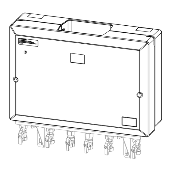
Logotherm LogoEco E PL B H-HW 1. Overview of components 1 Rear cover Heat exchanger domestic water Spool piece for heat meter in supply 2 Electronics line (not for permanent use) 3 LED indicator Strainer district heating supply Nipple for temperature sensor for 4 Mains adapter 230V heat meter, in return line Temperature sensor for heat... -
Page 6: Hydraulic Scheme
2. Hydraulic scheme We reserve the right to change designs and technical specifications of our products. -
Page 7: User Manual
VDI 2035 to protect the heating system and, for domestic water applications, the water quality at the place of use. Further information can be found in the download section at www.flamco.aalberts-hfc.com. Status indicatino LED light of the interface unit... - Page 8 Operation The delivery station is equipped with one heat exchanger for domestic water. The heat exchanger provides a physical separation (hydraulic) between the domestic installation and the heat distribution network. As a result, the medium in the heat distribution network does not come into contact with the medium in the domestic installation.
-
Page 9: Installation Specifications
Logotherm LogoEco E PL B H-HW CAUTION! Domestic hot water The domestic water temperature is controlled at approx. 55ºC. In case of a power outage during hot water tapping the interface unit stops controlling the domestic water temperature. This can result in domestic water temperatures lower or higher than 55ºC. -
Page 10: Maintenance And Inspection
5. Maintenance and inspection For proper operation of the interface unit, it is advised to have the following points inspected and maintained at least once every 24 months on the interface unit. Ask your heat supplier or your installer about the options for service and inspection. -
Page 11: Technical Specifications
Logotherm LogoEco E PL B H-HW 6. Technical specifications Types and specifications Type B16x34 B16x24 Domestic hot water temperature (45°C-65°C) °C Nominal flowrate (at TW=55°C, T_ =65°C) litre/min Prim Nominal power (at 10°C - 55°C) Pressure class design PN10 Minimal hot water draws off litre/min Keep warm temperature °C... -
Page 12: Pressure Drop-Flow-Diagram, Primary Side
7. Pressure drop-flow-diagram, primary side 7.1. Heat exchanger, type B16x34 7.2. Heat exchanger, type B16x24 We reserve the right to change designs and technical specifications of our products. -
Page 13: Delivery Range
Logotherm LogoEco E PL B H-HW 8. Delivery range 9. Additional items required 10. Dimensions > Delivery range... -
Page 14: Installation
11. Installation Note: Flow limiter for fix rail (connection C) are included in the HIU accessory pack. We reserve the right to change designs and technical specifications of our products. - Page 15 Logotherm LogoEco E PL B H-HW option I. option II. Connection Connection Size: Size: M10 x 1 F ½» F Caution! Removal of spool piece and Repla- cement for a heat meter or steel fitting piece (art. no.44452). Please contact your supplier.
-
Page 16: Room Thermostat (Optional)
12. Room thermostat (optional) Connecting the room thermostat: Remove the conductor. (only when a thermostat is used) Connect the room thermostat cable, with an isolated conductor*, to the room thermostat. * Sold separately CAUTION! A type of on/off thermostat with potential-free contacts or Honeywell round on/ off (T87G2014) thermostat with power stealing must be used. -
Page 17: Commissioning
Logotherm LogoEco E PL B H-HW 13. Commissioning Follow the steps shown below to commission the HIU. If leakage or other faults should occur, go to chapter “Troubleshoot”. CAUTION! Parts and components may be hot or energized. Contact may lead to shock, burn or electrocution. -
Page 18: Cover Sealing
14. Cover sealing CAUTION! Make sure that the electronic housing is in place and positioned so that all cables do not obstruct the hood when closed. We reserve the right to change designs and technical specifications of our products. -
Page 19: Troubleshoot
Logotherm LogoEco E PL B H-HW 15. Troubleshoot 15.1. Troubleshoot (end-user) LED indicator Green blinking Normal condition Blue blinking Domestic hot water delivery condition Red blinking Error White continuous Service mode (installer only) No LED Unit is switched off. What can you do? CAUTION!Always take in account the safety of yourself and others when performing a troubleshoot. -
Page 20: Troubleshoot (Installateur)
15.2. Troubleshoot (installateur) indicator Fault light Cause Solution Leakage (immediately close all valves on the terminal bracket under the drain set and the main valve to the mains water!) Leakage at the Tighten the swivel and/or check Gasket leaking swivel nut the gasket Leakage at the Tighten the sensor or replace it... - Page 21 Logotherm LogoEco E PL B H-HW indicator Fault light Cause Solution Valves on the terminal Open all valves on the terminal bracket are closed bracket. Radiator valves are closed Open radiator valves Fill the heating installation/CH to 2 bar. Check the delivery set Pressure in the heating and the heating installation/ system (CH) is too low (mi-...
- Page 22 indicator Fault light Cause Solution Domestic potable water Open mains domestic water Mains tap closed supply tap Flow-rate limiter is clogged Replace the excess flow-valve in or blocked the terminal bracket. No domestic Flow-sensor for domestic Replace the domestic water potable water tap water is blocked flow-sensor.
- Page 23 Logotherm LogoEco E PL B H-HW indicator Fault light Cause Solution Cap does not seal Cables are trapped between Ensure cables are free of the the insulating sheathing insulating sheath The electronics housing is Place the electronics housing in not in the correct position the correct position Cap does not close/seal pro-...
-
Page 24: Maintenance Checklist
16. Maintenance checklist Work to be carried out during annual maintenance. (by the specialist installer or factory customer service) Visual inspection* Comple- and OK? Screw connections and Leak-tightness check fittings Heat exchanger Leak-tightness check Check whether water or water depo- Safety trap** sits are present in the trap. -
Page 25: Spare Parts List
Logotherm LogoEco E PL B H-HW Functional check (electronic) Completed and OK? Check the status display** of the error codes, document these, follow Status error codes them up and initiate measures to remedy errors Compare settings in the controller Settings with the commissioning protocol and document any deviations. -
Page 26: Decommissioning, Dismantling, Environmental Protection And Disposal
18. Decommissioning, dismantling, envi- ronmental protection and disposal of elec- trical and electronic equipment During dismantling, the safety instructions and residual dangers mentioned (see Section 1) must be observed! Removal and disposal: Removal and disposal of the device should only be carried out by suitable trained experts. - Page 27 Logotherm LogoEco E PL B H-HW take-back). There is also the possibility to return old devices to the distributor free of charge if the external dimensions do not exceed 25 centimetres and the return is limited to three old devices per type of device (0:1 take-back). •...
- Page 28 We reserve the right to change designs and technical specifications of our products.
- Page 29 Logotherm LogoEco E PL B H-HW Inhaltsverzeichnis Symbole ������������������������������������������������������������������������������������������������������������������������������������� 30 Abkürzungen ��������������������������������������������������������������������������������������������������������������������������� 30 1� Übersicht der Komponenten ��������������������������������������������������������������������������������� 31 2� Hydraulikschema ������������������������������������������������������������������������������������������������������� 32 3� Gebrauchsanweisung ����������������������������������������������������������������������������������������������� 33 4� Spezifikationen für den Einbau ���������������������������������������������������������������������������� 35 5� Wartung und Inspektion ����������������������������������������������������������������������������������������� 36 6�...
-
Page 30: Symbole
Symbole WARNUNG, allgemeine Warnung Wenn möglich recyceln ACHTUNG, Elektrizität, Gefahr eines Torx-Schraubendreher Stromschlags oder einer Verletzung Torx 25 WARNUNG, heiße Oberfläche, Verbrennungs- gefahr Kreuzschlitzschraubendreher Wichtig Isolierter Schlitzschraubendre- isolated 230 V Wechselstrom Elektrische Bohrmaschine 230 V Teil entsorgen Händische Bearbeitung Maulschlüssel Abkürzungen Trinkwarmwasser Zentralheizung... -
Page 31: Übersicht Der Komponenten
Logotherm LogoEco E PL B H-HW 1. Übersicht der Komponenten Wärmeübertrager zur Trinkwasse- Hintere Abdeckung rerwärmung Passstück für Wärmezähler in der Vor- 2 Elektronik laufleitung (nicht für den Dauereinsatz) 3 LED-Anzeige Schmutzfänger im Fernwärmevorlauf Anschlussnippel für Temperaturfühler 4 Netzteil 230V des Wärmezählers, im Rücklauf Temperatursensor zur Trinkwassererwärmung, in... -
Page 32: Hydraulikschema
2. Hydraulikschema Wir behalten uns das Recht vor, Design und technische Spezifikationen unserer Produkte zu ändern. -
Page 33: Gebrauchsanweisung
Bei Heizungsanlagen berücksichtigen Sie bitte zum Schutz der Heizungsanlage die Beschaffenheit des Heizungswassers gemäß VDI 2035 und bei Trinkwassererwärmung die Wasserqualität am Verwendungsort� Weitere Informationen finden Sie im Down- loadbereich unter www�flamco�aalberts-hfc�com� Statusanzeige-LED der Übergabestation Allgemein Die Übergabestation befindet sich in der Blau blinkend Trinkwasser-Erwärmung�... - Page 34 Betrieb Die Übergabestation ist mit einem Wärmeübertrager zur Trinkwassererwärmung aus- gestattet� Der Wärmeübertrager sorgt für eine physikalische Trennung (hydraulisch) zwischen der Wohnungsinstallation und dem Fernwärmeverteilnetz� Dadurch kommt das Medium im Fernwärmeverteilnetz nicht mit dem Medium in der Wohnungsinstallation in Kontakt� Die Wärme wird vom Fernwärmeverteilnetz über den Wärmeübertrager an das Trinkwassersystem übergeben�...
-
Page 35: Spezifikationen Für Den Einbau
Logotherm LogoEco E PL B H-HW Vorrangschaltung Die Schnittstelleneinheit ist mit einer Vorrangschaltung ausgestattet� Das Heizungs- regelventil sorgt dafür, dass bei einer Trinkwarmwasserentnahme der volle Differenz- druck aus dem Fernwärmenetz für die Trinkwassererwärmung zur Verfügung steht� Während der Warmwasserentnahme wird die Wärmezufuhr zum Heizungskreislauf unterbrochen�... -
Page 36: Wartung Und Inspektion
5. Wartung und Inspektion Für einen ordnungsgemäßen Betrieb der Übergabestation wird empfohlen, die folgen- den Punkte mindestens alle 24 Monate an der Schnittstelleneinheit überprüfen und warten zu lassen� Erkundigen Sie sich bei Ihrem Wärmelieferanten oder Ihrem Installa- teur über die Möglichkeiten der Wartung und Inspektion� Wartung und Reparatur der Übergabestation dürfen nur von zugelassenem Fachpersonal durchgeführt werden�... -
Page 37: Technische Spezifikationen
Logotherm LogoEco E PL B H-HW 6. Technische Spezifikationen Typen und Spezifikationen B16x34 B16x24 Trinkwarmwassertemperatur (45°C-65°C) °C Nenndurchfluss (bei TW=55°C, =65°C) Liter/min T_Prim Nennleistung (bei 10°C - 55°C) Druckklassenausführung PN10 Minimale Warmwasserentnahme Liter/min Warmhaltung °C 40 (einstellbar: 25 - 65) Warmhaltezeit nach dem Zapfvorgang immer (einstellbar: 0 - immer) Programm zur Verhütung von Legionellen... -
Page 38: Druckverlust-Volumenstrom-Diagramm, Primärseite
7. Druckverlust-Volumenstrom-Diagramm, Primärseite 7.1. Wärmeübertrager, Typ B16x34 7.2. Wärmeübertrager, Typ B16x24 Wir behalten uns das Recht vor, Design und technische Spezifikationen unserer Produkte zu ändern. -
Page 39: Lieferumfang
Logotherm LogoEco E PL B H-HW 8. Lieferumfang 9. Zusätzlich benötigte Artikel 10. Maße > Lieferumfang... -
Page 40: Installation
11. Installation Notiz: Durchflussbegrenzer für Anschluss-/Montageschiene (Anschluss C) sind im HIU-Beipack enthalten� Wir behalten uns das Recht vor, Design und technische Spezifikationen unserer Produkte zu ändern. - Page 41 Logotherm LogoEco E PL B H-HW Option I� Option II� Anschlussgröße: Anschlussgröße: M10 x 1" IG ½" IG Achtung! Entfernen des Passstücks und Ersatz für einen Wärmezähler oder Me- tallpassstück (Art�-Nr� 44452)� Bitte wenden Sie sich an Ihren Lieferanten� > Installation...
-
Page 42: Raumthermostat (Optional)
12. Raumthermostat (optional) Anschluss des Raumthermostats: 1� Entfernen Sie den Leiter� (nur bei Verwendung eines Thermostats) 2� Schließen Sie das Raumthermostatkabel, mit isoliertem Leiter*, an das Raumthermostat an� * Separat erhältlich ACHTUNG! Es muss ein Ein-/Aus-Thermostattyp mit potentialfreien Kontakten oder ein runder Ein-/Aus-Thermostat (T87G2014) von Honeywell mit Stromunterbrechung verwendet werden�... -
Page 43: Inbetriebnahme
Logotherm LogoEco E PL B H-HW 13. Inbetriebnahme Befolgen Sie die unten aufgeführten Schritte, um die HIU in Betrieb zu nehmen� Sollten Undichtigkeiten oder andere Störungen auftreten, fahren Sie mit dem Kapitel „Fehlerbe- hebung“ fort� ACHTUNG! Teile und Komponenten können heiß oder unter Spannung stehen� Kontakt kann zu Stromschlägen, Verbrennungen oder einem Stromschlag führen�... -
Page 44: Gehäuse-Haube
14. Gehäuse-Haube ACHTUNG! Stellen Sie sicher, dass das Elektronikgehäuse an seinem Platz ist und so positioniert ist, dass keine Kabel die Haube im geschlossenen Zustand behindern� Wir behalten uns das Recht vor, Design und technische Spezifikationen unserer Produkte zu ändern. -
Page 45: Fehlerbehebung
Logotherm LogoEco E PL B H-HW 15. Fehlerbehebung 15.1. Fehlerbehebung (Endbenutzer) LED-Anzeige Grün blinkend Normaler Zustand Bedingungen für die Blau blinkend Trinkwarmwasserbereitung Rot blinkend Fehler Weiß durchgehend Servicemodus (nur Installateur) Keine LED Gerät ist ausgeschaltet� Was kannst du tun? ACHTUNG!Berücksichtigen Sie bei der Fehlerbehebung stets Ihre eigene Si- cherheit und die Sicherheit anderer�... -
Page 46: Fehlerbehebung (Installateur)
15.2. Fehlerbehebung (Installateur) LED- Anzeige Ursache Lösung Fehler Undichtigkeit (sofort alle Ventile an der Anschlussschiene unter der Ablaufgarnitur und das Haupt- ventil zum Leitungswasser schließen!) Leckage an der Überwurfmutter festziehen und/ Dichtung undicht Überwurfmutter oder Dichtung prüfen Undichtigkeit am Den Sensor festziehen oder durch O-Ring undicht Temperatursensor einen neuen ersetzen�... - Page 47 Logotherm LogoEco E PL B H-HW LED- Anzeige Ursache Lösung Fehler Ventile an der Öffnen Sie alle Ventile an der Anschlussschiene sind Anschlussschiene� geschlossen Heizkörperventile sind Heizkörperventile öffnen geschlossen Heizungsanlage/ZH auf 2 bar auf- füllen� Prüfen Sie die gelieferten Der Druck im Heizungssystem Komponenten und die Heizungs-/ (CH) ist zu niedrig (min- Zentralinstallation auf eventuelle...
- Page 48 LED- Anzeige Ursache Lösung Fehler Trinkwasser für den Hausgebrauch Öffnen Sie den Haupthahn der Haupthahn geschlossen Hauswasserversorgung Durchflussbegrenzer ist Ersetzen Sie das Überströmventil verstopft oder blockiert in der Anschlusshalterung� Durchflusssensor für Leitungs- Ersetzen Sie den Trinkwas- Kein Trinkwasser wasser im Haushalt ist blockiert ser-Durchflusssensor�...
- Page 49 Logotherm LogoEco E PL B H-HW LED- Anzeige Ursache Lösung Fehler Haube dichtet nicht ab Kabel werden zwischen Stellen Sie sicher, dass die Kabel der Isolierummantelung frei von der Isolierhülle sind eingeklemmt Platzieren Sie das Elektro- Das Elektronikgehäuse sitzt Die Haube nikgehäuse in der richtigen nicht in der richtigen Position schließt nicht...
-
Page 50: Wartungscheckliste
16. Wartungscheckliste Im Rahmen der jährlichen Wartung durchzuführende Arbeiten� (durch den Fachinstallateur oder Werkskundendienst) Visuelle Inspektion* Eledigt und ok? Verschraubungen und 1� Dichtheitsprüfung Armaturen 2� Wärmetauscher Dichtheitsprüfung Prüfen Sie, ob sich Wasser oder Wasse- 3� Sicherheitswanne** rablagerungen im Siphon befinden� Überprüfen Sie die elektrische Verka- belung auf Auffälligkeiten (z�B�... -
Page 51: Ersatzteile
Logotherm LogoEco E PL B H-HW Funktionskontrolle (elektronisch) Eledigt und ok? Prüfen Sie die Statusanzeige** der Fehlercodes, dokumentieren Sie diese, 1� Statusfehlercodes gehen Sie ihnen nach und leiten Sie Maßnahmen zur Fehlerbehebung ein Einstellungen im Regler mit dem Inbe- triebnahmeprotokoll vergleichen und 2�... -
Page 52: Elektro- Und Elektronikgeräten
18. Außerbetriebnahme, Demontage, Umweltschutz und Entsorgung von Elektro- und Elektronikgeräten Bei der Demontage sind die genannten Sicherheitshinweise und Restgefahren (siehe Abschnitt 1) zu beachten! Demontage und Entsorgung: Die Demontage und Entsorgung des Gerätes darf nur durch entsprechend geschultes Fachpersonal erfolgen� Beachten Sie bei der Entsorgung der Hilfs- und Betriebsstoffe unbedingt die Angaben in den Sicherheitsdatenblättern, welche von den Lieferanten der Hilfs- und Betrie- bsstoffe zur Verfügung gestellt werden müssen�... - Page 53 Logotherm LogoEco E PL B H-HW kostenfrei beim Vertreiber zurückzugeben, wenn die Außenmaße 25 Zentimeter nicht überschreiten und die Rückgabe auf drei Altgeräte je Gerätetyp begrenzt ist (0:1 Rücknahme)� • Handel: Vertreiber, die über eine Verkaufsfläche für Elektro- und Elektronikgeräte von mindestens 400 Quadratmetern verfügen, sind zur Rücknahme von Elektro- und Elektronik-Altgeräten verpflichtet�...
- Page 54 Wir behalten uns das Recht vor, Design und technische Spezifikationen unserer Produkte zu ändern.
- Page 55 Logotherm LogoEco E PL B H-HW Spis treści Symbolika ....................56 Skróty ......................56 Przegląd komponentów ..............57 Schemat hydrauliczny ...............58 Instrukcja obsługi ................59 Specyfikacje instalacji ...............61 Konserwacja i przegląd ..............62 Specyfikacja techniczna ..............63 Wykres przepływu/spadku ciśnienia, strona pierwotna ....64 7.1. Wymiennik ciepła typ B16x34 ................64 7.2.
-
Page 56: Symbolika
Symbolika Jeśli to możliwe, poddaj UWAGA, ostrzeżenie ogólne recyklingowi OSTRZEŻENIE, prąd elektryczny, ryzyko Śrubokręt typu Torx porażenia lub obrażeń Torx 25 UWAGA, gorąca powierzchnia, ryzyko poparzeń Śrubokręt krzyżakowy Ważny isolated Izolowany śrubokręt płaski 230 V Prąd przemienny Wiertarka elektryczna 230 V Pozbądź... -
Page 57: Przegląd Komponentów
Logotherm LogoEco E PL B H-HW 1. Przegląd komponentów 1 Pokrywa tylna Wymiennik ciepła wody użytkowej Wstawka licznika ciepła na zasilaniu 2 Sterownik (nie do stałego użytku) 3 Wskaźnik ledowy Filtr na zasilaniu strona pierwotna Króciec do czujnika temperatury z 4 Zasilacz sieciowy 230V licznika ciepła (powrót do sieci) Czujnik temperatury wody grzewczej... -
Page 58: Schemat Hydrauliczny
2. Schemat hydrauliczny Zastrzegamy sobie prawo do wprowadzania zmian w konstrukcji i specyfikacjach technicznych naszych produktów. -
Page 59: Instrukcja Obsługi
Więcej informacji można znaleźć w sekcji do pobrania na stronie www.flamco.aalberts-hfc.com. Wskaźnik stanu diody LED stacji Ogólne Logoterma znajduje się w pozycji Migające na niebiesko przygotowania ciepłej wody użytkowej. - Page 60 Działanie Stacja mieszkaniowa wyposażona jest w jeden wymiennik ciepła do wody użyt- kowej. Wymiennik ciepła zapewnia fizyczne (hydrauliczne) rozdzielenie instalacji domowej c.w.u. i wody grzewczej. Dzięki temu woda grzewcza nie ma kontaktu z wodą użytkową. Ciepło przekazywane jest z instalacji c.o. za pomocą wymiennika ciepła do instalacji ciepłej wody użytkowej.
-
Page 61: Specyfikacje Instalacji
Logotherm LogoEco E PL B H-HW UWAGA! Ciepła woda użytkowa Temperaturę wody użytkowej utrzymuje się na poziomie ok. 55ºC. W przypadku zaniku zasilania w trakcie poboru ciepłej wody, Logoterma przestaje kontrolować temperaturę wody użytkowej. Może to spowodować, że temperatura wody użytko- wej będzie niższa lub wyższa niż... -
Page 62: Konserwacja I Przegląd
5. Konserwacja i przegląd Aby zapewnić prawidłową pracę stacji Logoterma, zaleca się przeprowadzanie kontroli i konserwacji następujących punktów stacji co najmniej raz na 24 miesiące. Zapytaj swojego dostawcę ciepła lub instalatora o dostępne opcje serwisu i przeglądów. Konserwację i naprawy stacji muszą wykonywać uprawnieni fachowcy. -
Page 63: Specyfikacja Techniczna
Logotherm LogoEco E PL B H-HW 6. Specyfikacja techniczna Typy i specyfikacje B16x34 B16x24 Temperatura ciepłej wody użytkowej °C 45°C-65°C Przepływ nominalny (przy TW=55°C, T_ litr/min =65°C) Prim Moc znamionowa (przy 10°C - 55°C) Ciśnienie znamionowe PN10 Minimalny pobór ciepłej wody litr/min Funkcja podtrzymania ciepła °C... -
Page 64: Wykres Przepływu/Spadku Ciśnienia
(2) Możliwość regulacji za pomocą specjalnego oprogramowania serwisowego i kabla dla instalatorów. (3) Typ termostatów włącz/wyłącz z bezpotencjałowymi stykami. 7. Wykres przepływu/spadku ciśnienia, strona pierwotna 7.1. Wymiennik ciepła typ B16x34 7.2. Wymiennik ciepła typ B16x24 Zastrzegamy sobie prawo do wprowadzania zmian w konstrukcji i specyfikacjach technicznych naszych produktów. -
Page 65: Zakres Dostawy
Logotherm LogoEco E PL B H-HW 8. Zakres dostawy 9. Wymagane dodatkowe elementy > Zakres dostawy... -
Page 66: Wymiary
10. Wymiary 11. Instalacja Notatka: Ogranicznik przepływu dla szyny montażowej (przyłącze C) znajduje się w zes- tawie akcesoriów. Zastrzegamy sobie prawo do wprowadzania zmian w konstrukcji i specyfikacjach technicznych naszych produktów. - Page 67 Logotherm LogoEco E PL B H-HW > Instalacja...
-
Page 68: Termostat Pokojowy (Opcjonalnie)
opcja I. opcja II. Rozmiar Rozmiar połączenia: M10 połączenia: UWAGA! x 1 F ½» F Demontaż wstawki i wymiana licznika ciepła lub elementu stalowego (nr art. 44452). Skontaktuj się ze swoim dostawcą. 12. Termostat pokojowy (opcjonalnie) Podłączenie termostatu pokojowego: Usunąć przewód (tylko w przypadku użycia termostatu) Podłącz kabel termostatu pokojowego do termostatu pokojowego za pomocą... - Page 69 Logotherm LogoEco E PL B H-HW UWAGA! Należy stosować termostat typu włącz/wyłącz ze stykami bezpotencjałowymi. > Termostat pokojowy (opcjonalnie)
-
Page 70: Rozruch/Uruchomienie
13. Rozruch/Uruchomienie Aby uruchomić stację, wykonaj poniższe czynności. W przypadku wystąpienia wycieku lub innych usterek należy zapoznać się z rozdziałem „Rozwiązywanie problemów”. UWAGA! Części i podzespoły mogą być gorące lub pod napięciem. Kontakt może spowo- dować obrażenia, oparzenie lub porażenie prądem. Zamknij wszystkie punkty poboru w lokalu. -
Page 71: Uszczelnienie Pokrywy
Logotherm LogoEco E PL B H-HW 14. Uszczelnienie pokrywy UWAGA! Upewnij się, że obudowa elektroniki jest na swoim miejscu i ustawiona tak, aby żadne kable nie przeszkadzały w zamykaniu pokrywy. > Uszczelnienie pokrywy... -
Page 72: Rozwiązywanie Problemów
15. Rozwiązywanie problemów 15.1. Rozwiązywanie problemów (użytkownik końcowy) Wskaźnik ledowy Zielone miganie Normalna praca Stan dostarczania ciepłej wody Niebieski migający użytkowej Czerwone miganie Błąd Biały ciągły Tryb serwisowy (tylko instalator) Brak działania diody LED Jednostka jest wyłączona. Co możesz zrobić? UWAGA!Podczas rozwiązywania problemów zawsze miej na uwadze bezpieczeństwo swoje i innych. -
Page 73: Rozwiązywanie Problemów (Instalator)
Logotherm LogoEco E PL B H-HW 15.2. Rozwiązywanie problemów (instalator) Kontrolka Wada Przyczyna Rozwiązanie Wyciek (natychmiast zamknąć wszystkie zawory na konsoli montażowej i zawór główny dopływu wody!) Wyciek przy Dokręć połączenie obrotowe i/ nakrętce obro- Nieszczelna uszczelka lub sprawdź uszczelkę towej Wyciek przy Nieszczelność... - Page 74 Kontrolka Wada Przyczyna Rozwiązanie Zawory na konsoli mon- Otwórz wszystkie zawory na tażowej są zamknięte konsoli. Zawory grzejnikowe są Otwórz zawory grzejnikowe zamknięte Napełnij instalację grzewczą/ CH do ciśnienia 2 barów. Ciśnienie w instalacji Sprawdź, czy w stacji i insta- grzewczej (CH) jest zbyt lacji grzewczej/CH nie ma wy- niskie (minimum 1 bar).
- Page 75 Logotherm LogoEco E PL B H-HW Kontrolka Wada Przyczyna Rozwiązanie Luźne wtyczki czujników Sprawdź połączenia wtyczek lub złe połączenie wtyczki z wiązki przewodów i ponownie wiązką przewodów uruchom stację. Migające Wymień uszkodzony czujnik(i) i czerwone Czujnik(i) uszkodzony(e) ponownie uruchom stację. Obieg grzewczy Elektronika lub wiązka Skontaktuj się...
- Page 76 Kontrolka Wada Przyczyna Rozwiązanie Niepodłączony do gniazdka Włóż wtyczkę do gniazdka (230 V AC). Brak napięcia (230VAC) w Sprawdź napięcie (230VAC) w gniazdku ściennym gniazdku ściennym Przewód zasilający 230VAC Podłącz prawidłowo przewód nie jest prawidłowo przy- zasilający 230VAC do modułu mocowany do urządzeń...
-
Page 77: Lista Kontrolna Podczas Prac Konserwacyjnych
Logotherm LogoEco E PL B H-HW Kontrolka Wada Przyczyna Rozwiązanie Grzechoczący Migające Sprawdź kierunek przepływu dźwięk przy na zie- Czujnik przepływu jest nie- (strzałka) na czujniku odkręcaniu lono lub prawidłowo zainstalowany przepływu kranu czerwono Skontaktuj się ze swoim dos- Inne awarie tawcą... - Page 78 Temperatura zasilania dla Temperatura zgodnie ze specyfikacją przygotowania ciepłej (patrz protokół uruchomienia) wody Przepływ do przygotowa- Przepływ zgodnie ze specyfikacją (pa- nia ciepłej wody użytko- trz protokół uruchomienia) Po zakończeniu poboru ciepłej wody Mostek cyrkulacyjny** użytkowej przewód powrotny po stro- nie pierwotnej musi pozostać...
-
Page 79: Lista Części Zamiennych
Logotherm LogoEco E PL B H-HW 17. Lista części zamiennych Sterownik ME-10101.0100 Elektroniczny siłownik zaworu (SMV) ME-80590.83 Czujnik przepływu ME-10101.0080 Wymiennik ciepła typ B16x34 ME-10101.0098 Wymiennik ciepła typ B16x24 ME-10101.0099 Wstawka mosiężna ¾” x 110 mm (do licznika ME-90352.13 ciepła) Filtr ¾”... -
Page 80: Wycofanie Z Eksploatacji, Demontaż, Ochrona Środowiska I Utylizacja Sprzętu Elektrycznego I Elektronicznego
18. Wycofanie z eksploatacji, demontaż, ochrona środowiska i utylizacja sprzętu elektrycznego i elektronicznego Podczas demontażu należy bezwzględnie przestrzegać wskazówek bez- pieczeństwa i innych zagrożeń wymienionych w rozdziale 1! Usuwanie i utylizacja: Demontaż i utylizację urządzenia mogą przeprowadzać wyłącznie odpowiednio przeszkoleni specjaliści. Przy utylizacji materiałów pomocniczych i eksploatacyjnych należy zawsze sto- sować... - Page 81 Logotherm LogoEco E PL B H-HW W przypadku zakupu nowego urządzenia tego samego typu dystrybutor ma obowiązek przyjąć zwrot urządzenia bezpłatnie (stosunek odbioru 1:1). Istnieje również możliwość bezpłatnego zwrotu starych urządzeń do dystrybutora, jeśli ich wymiary zewnętrzne nie przekraczają 25 centymetrów, a zwrot jest ogra- niczony do trzech starych urządzeń...
- Page 82 70 countries. This is done from Flamco sales offices and via distributors who know the local market, and can give you the right advice at all times. Aalberts hydronic flow control Nederland Postbus 30110 1303 AC Almere...
- Page 83 Logotherm LogoEco E PL B H-HW Inhaltsverzeichnis Liste des symboles ..................84 Abréviations ....................84 Aperҫu des composants ..............85 Schéma hydraulique ................86 Manuel d'utilisation ................87 Spécifications d'installation ..............90 Inspection et maintenance ..............91 Caractéristiques techniques .............92 Diagramme perte de charge-débit, côté primaire ......93 7.1.
-
Page 84: Liste Des Symboles
Liste des symboles AVERTISSEMENT, avertissement général Recycler si possible AVERTISSEMENT, électricité, risque de Tournevis Torx choc ou de blessure Torx 25 AVERTISSEMENT, surface chaude, risque de brûlures Tournevis Philips Important isolated Tournevis plat isolé Courant alternatif 230 V Perceuse électrique 230 V Jeter la pièce Traitement manuel... -
Page 85: Aperҫu Des Composants
Logotherm LogoEco E PL B H-HW 1. Aperҫu des composants Echangeur de chaleur production eau 1 Couvercle arrière chaude sanitaire Manchette pour emplacement comp- 2 Boitier de contrôle teur de chaleur (pas pour une utilisation permanente) 3 Indicateur LED Filtre alimentation eau de chauffage Doigt de gant pour capteur de 4 Adaptateur secteur 230V température du compteur dans la... -
Page 86: Schéma Hydraulique
2. Schéma hydraulique Nous nous réservons le droit de modifier la conception et les spécifications techniques de nos produits. -
Page 87: Manuel D'utilisation
De plus amples informations sont disponibles dans la section des téléchargements à l' adresse www.flamco. aalberts-hfc.com.. Voyant LED d'indication d'état du module thermique d’appartement Général Le module est en position eau chaude Bleu clignotant sanitaire. - Page 88 Unité d'interface sans câble de raccordement du thermostat d'ambiance et sans préréglage Clignotement lent en vert HIU est en veille ou en mode chauffage. (environ une fois par seconde) Fonctionnement Le poste de livraison est équipé d'un échangeur de chaleur pour la production d’eau chaude sanitaire.
- Page 89 Logotherm LogoEco E PL B H-HW régulation électronique et à un capteur de débit, garantit une température de l'eau sanitaire d'environ 55ºC. Le module thermique d’appartement a un minimum de débit de 1 l/min. Ex-works (par défaut), l'échangeur de chaleur est maintenu en permanence à température pour fournir de l'eau chaude sanitaire le plus rapidement possible en cas de demande d'eau chaude sanitaire.
-
Page 90: Spécifications D'installation
4. Spécifications d'installation Lors de l'installation de du module thermique d’appartement, il faut tenir compte du décret sur la construction, des exigences de sécurité pour les installations de chauffage central et des exigences générales pour l'eau sanitaire. L'installation ne peut être effectuée que par du personnel agréé. L’agrément peut être accordé par les compagnies d'énergie, d'électricité... -
Page 91: Inspection Et Maintenance
Logotherm LogoEco E PL B H-HW 5. Inspection et maintenance Pour un bon fonctionnement du module thermique d’appartement, il est conseillé de faire inspecter et entretenir les points suivants au moins une fois tous les 24 mois sur l'unité d'interface. Renseignez-vous auprès de votre fournisseur de chaleur ou de votre installateur sur les possibilités d'entretien et d'inspection. -
Page 92: Caractéristiques Techniques
6. Caractéristiques techniques Types et spécifications Type B16x34 B16x24 Température de l'eau chaude sanitaire °C (45°C-65°C) Débit nominal (à TW=55°C, =65°C) litre/min T_Prim Puissance nominale (à 10°C - 55°C) Classe de pression PN10 Tirage minimal de l'eau chaude litre/min Température de maintien au chaud °C 40 (réglable : 25 - 65) Temps de maintien au chaud après puisage... -
Page 93: Diagramme Perte De Charge-Débit, Côté Primaire
Logotherm LogoEco E PL B H-HW 7. Diagramme perte de charge-débit, côté primaire 7.1. Échangeur de chaleur, type B16x34 7.2. Échangeur de chaleur, type B16x24 > Diagramme perte de charge-débit, côté primaire... -
Page 94: Contenu Du Colis À La Livraison
8. Contenu du colis à la livraison 9. Éléments supplémentaires requis 10. Dimensions de l'appareil Nous nous réservons le droit de modifier la conception et les spécifications techniques de nos produits. -
Page 95: Installation
Logotherm LogoEco E PL B H-HW 11. Installation Remarque : Le limiteur de débit pour le rail fixe (connexion C) est inclus dans le pack d'ac- cessoires MTA. > Installation... - Page 96 Nous nous réservons le droit de modifier la conception et les spécifications techniques de nos produits.
- Page 97 Logotherm LogoEco E PL B H-HW option I. option II. Taille de la Connexion connexion : M10 ½" F Attention : x 1 F Retrait de la manchette compteur remplacement par un compteur de chaleur ou par une pièce de montage en acier (art.
-
Page 98: Thermostat D'ambiance (En Option)
12. Thermostat d'ambiance (en option) Raccordement du thermostat d'ambiance (en option) Retirer le conducteur. (uniquement en cas d'utilisation d'un thermostat) Connecter le câble du thermostat d'ambiance, avec un conducteur isolé*, au thermostat d'ambiance. * Vendu séparément Attention : Il faut utiliser un type de thermostat marche/arrêt avec des contacts sans potentiel ou un thermostat rond marche/arrêt Honeywell (T87G2014) avec une tension d'alimentation. -
Page 99: Mise En Service
Logotherm LogoEco E PL B H-HW 13. Mise en service Suivez les étapes ci-dessous pour mettre en service le MTA. En cas de fuite ou d'autres problèmes, voir le chapitre "Dépannage". Attention : Les pièces et les composants peuvent être chauds ou sous tension. Tout contact peut entraîner un choc, une brûlure ou une électrocution. -
Page 100: Etanchéité Du Couvercle
14. Etanchéité du couvercle Attention : Assurez-vous que le boîtier électronique est en place et positionné de manière à ce que tous les câbles n'obstruent pas le capot lorsqu'il est fermé. Nous nous réservons le droit de modifier la conception et les spécifications techniques de nos produits. -
Page 101: Dépannage
Logotherm LogoEco E PL B H-HW 15. Dépannage 15.1. Dépannage (utilisateur final) Indicateur LED Vert clignotant Condition normale Bleu clignotant Condition de livraison de l'eau chaude sanitaire Rouge clignotant Erreur Blanc en continu Mode service (installateur uniquement) Pas de LED L'appareil est éteint. -
Page 102: Dépannage (Installateur)
15.2. Dépannage (installateur) Indicateur lumineux Défaut Cause Solution Fuite (fermez immédiatement toutes les vannes sur le support sous le set de vidange et la vanne principale vers le réseau d'eau !) Fuite au niveau Serrez l'émerillon et/ou vérifiez de l'écrou pivo- Fuite du joint le joint d'étanchéité... - Page 103 Logotherm LogoEco E PL B H-HW Indicateur lumineux Défaut Cause Solution Les vannes du support de Ouvezr toutes les vannes sur le connexion sont fermées support du terminal. Les vannes des radiateurs Ouvrez les vannes des radia- sont fermées teurs Remplissez l'installation de chauffage/CH à...
- Page 104 Indicateur lumineux Défaut Cause Solution Le(s) connecteur(s) du cap- Vérifiez les connexions des teur est/sont desserré(s) ou fiches du faisceau de câbles et mal connecté(s) au faisceau redémarrez le kit de livraison de câbles Rouge Remplacez le(s) capteur(s) clignotant Capteur(s) défectueux défectueux et redémarrer l'en- semble de livraison.
- Page 105 Logotherm LogoEco E PL B H-HW Indicateur lumineux Défaut Cause Solution Non branché sur une prise Insérez la fiche dans la prise murale (230VAC). Pas de tension (230VAC) à Vérifiez la tension (230VAC) à la prise murale la prise murale le câble d'alimentation Installez correctement le câble 230VAC n'est pas correcte-...
-
Page 106: Liste Des Contrôles Pour L'entretien
Indicateur lumineux Défaut Cause Solution Le bouchon n'est pas étanche Les câbles sont coincés S'assurez que les câbles sont entre les gaines isolantes exempts de la gaine isolante Le boîtier électronique n'est Placez le boîtier électronique Le capuchon ne pas dans la bonne position dans la bonne position se ferme pas/ Le tuyau d'écartement n'est... - Page 107 Logotherm LogoEco E PL B H-HW Contrôle fonctionnel (mécanique) Complété conforme Piège à saletés Vérifiez et nettoyer le tamis Vérifiez la fonctionnalité et l'opérabilité robinet d'arrêt ; remplacer si défectueux Contrôlez le fonctionnement du clapet Vanne de zone** de la vanne; le remplacer s'il est défec- tueux Température de départ Température conforme aux spécifica-...
-
Page 108: Liste Des Pièces Détachées
17. Liste des pièces détachées ME-10101.0100 Contrôleur ME-80590.83 8, 10 Vanne à moteur pas à pas (SMV) ME-10101.0080 Capteur de débit ME-10101.0098 Échangeur de chaleur, type B16x34 ME-10101.0099 Échangeur de chaleur, type B16x24 ME-90352.13 Bobine en laiton ¾" x 110 mm (pour compteur de chaleur) ME-10101.0023 Crépine ¾"... -
Page 109: Déclassement, Démantèlement, Protection De L'environnement Et
Logotherm LogoEco E PL B H-HW 18. Déclassement, démantèlement, pro- tection de l'environnement et élimination des équipements électriques et électro- niques Lors du démontage, les consignes de sécurité et les dangers résiduels mentionnés (voir chapitre 1) doivent être respectés ! Enlèvement et élimination : Le démontage et l'élimination de l'appareil ne doivent être effectués que par des experts qualifiés. - Page 110 distributeurs sous certaines conditions. Le distributeur doit reprendre gratuite- ment l'appareil lors de l'achat d'un nouvel appareil du même type (reprise 1:1). Il est également possible de renvoyer gratuitement au distributeur les anciens appareils dont les dimensions extérieures ne dépassent pas 25 centimètres, dans la limite de trois anciens appareils par type d'appareil (0:1 take-back).
- Page 111 Logotherm LogoEco E PL B H-HW > Déclassement, démantèlement, protection de l'environnement et élimination des équipements électriques et électroniques...
- Page 112 70 countries. This is done from Flamco sales offices and via distributors who know the local market, and can give you the right advice at all times. Aalberts hydronic flow control Nederland Postbus 30110 1303 AC Almere...
Need help?
Do you have a question about the flamco Logotherm LogoEco E PL B H-HW and is the answer not in the manual?
Questions and answers