Advertisement
Available languages
Available languages
Quick Links
NexusValve circulation valve
Thermostatically controlled circulation valve / Thermostatisch
gesteuertes Zirkulationsventil / Thermostatisch geregelde
circulatieklep / Vanne de bouclage thermostatique
ENG Installation and operating instruction ................... 3
DEU Montage- und Bedienungsanleitung ..................... 31
NDL
Montage- en gebruikshandleiding ..........................59
FRA
Installation et mode d'emploi ....................................87
Advertisement

Related Manuals for Aalberts flamco comap NexusValve TW

Summary of Contents for Aalberts flamco comap NexusValve TW
- Page 1 NexusValve circulation valve Thermostatically controlled circulation valve / Thermostatisch gesteuertes Zirkulationsventil / Thermostatisch geregelde circulatieklep / Vanne de bouclage thermostatique ENG Installation and operating instruction ....3 DEU Montage- und Bedienungsanleitung ..... 31 Montage- en gebruikshandleiding ......59 Installation et mode d’emploi ........87...
- Page 2 Scan for online manuals www.aalberts-hfc.com made in Europe...
- Page 3 Thermostatically controlled circulation valve Table of contents Safety instructions .......................4 1.1. Rules/regulations ........................... 4 1.2. Intended use ............................ 5 1.3. Initial operation ..........................5 1.4. Working on the system ....................... 6 1.5. Liability .............................. 6 Introduction ........................7 2.1. Description ............................7 2.2.
- Page 4 1. Safety instructions Please read the instructions carefully before installation The installation and initial operation of the assembly may be carried out only by an authorised specialist company. Prior to starting work, familiarise yourself with all parts and how they are handled. The application examples in these operating instructions are ideas sketched out.
- Page 5 Thermostatically controlled circulation valve DIN EN 1717: Protection of potable water against contaminations DIN 4751: Safety equipment Electrical connection: VDE 0100: Erection of electrical equipment, grounding, protective conductor, potential equalisation conductor. VDE 0701: Repair, modification and testing of electrical devices. VDE 0185: General aspects on the erection of lightning protection systems.
- Page 6 1.4. Working on the system The plant has to be de-energised and to be checked for the absence of voltage (such as on the separate fuse or a master switch). Secure the plant against unintentional restart. (If gas is used as fuel, close the gas shut-off valve and secure against unintentional opening.) Repair work on component parts with a safety-relevant function is impermissible.
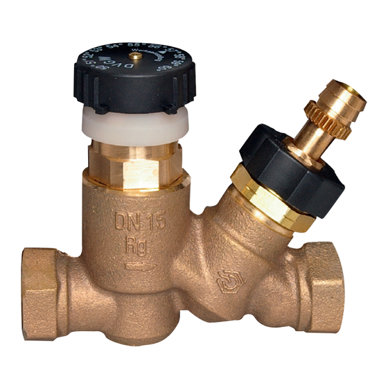
- Page 7 Thermostatically controlled circulation valve 2. Introduction NexusValve TW Thermostatically controlled circulation valve - DN15- DN25 2.1. Description The NexusValve TW is a thermostatic valve installed in domestic water systems on circulation lines. It is used to balance the system by controlling flow in reference to the water temperature.
- Page 8 2.3. Design The NexusValve TW consists of a thermostatic valve unit which can be set to the temperature at which the water flow should be restricted. The NexusValve TW has a setting range of 50 ° C to 60 ° C. A static balancing valve is built into the NexusValve TW to limit the flow.
- Page 9 Thermostatically controlled circulation valve 2.4. System balancing and servicing The NexusValve TW temperature setting is provided by turning the black knob. The scale is accurate and enables temperature setting with the accuracy of ±1°C. The Nexus Valve TW is set to a required temperature by turning the black knob against the white reference mark on the collar underneath the knob.
- Page 10 2.5. Operation The NexusValve TW secures quick access to hot water in all water points by ensuring the required circulation flow throughout the domestic water system. This is achieved by setting the temperature at which the valve should restrict the flow in a riser or branch.
- Page 11 Thermostatically controlled circulation valve The NexusValve TW in domestic water systems with circulation. The flow in the first riser is restricted by the NexusValve TW when the hot water reaches the valve. As a result water is forced to the next riser. When the NexusValve TW closes in the second riser, the hot water is provided to the next riser and even- tually distributed within the whole system.
- Page 12 2.6. System disinfection Some regulations require that thermal disinfected is carried out by providing hot water of at least 70°C in the entire domestic hot water system. The NexusValve TW enables this type of disinfection by balancing the system also at that high temperature. The thermal disinfection poses a risk of scalding when water is tapped.
- Page 13 Thermostatically controlled circulation valve 2.7. Mounting The NexusValve TW must be installed so that the flow direction marked on the valve is respected. Installation in any position is allowed. The temperature setting is provided by rotating the knob with temperature scale. A white reference mark on the collar underneath the knob indicates the current temperature setting.
- Page 14 3. Applications Application 1 - Domestic water system with circulation The NexusValve TW is used in domestic water systems with circulation. It is installed in the circulation pipe of each riser or a branch with several water points. Application 2 - Domestic water system with circulation and thermostatic mixing valves The NexusValve TW is used in domestic water systems with circulation where thermal disinfection is carried out.
- Page 15 Thermostatically controlled circulation valve 4. Product data sheet 4.1. NexusValve TW DN 15-25 4.1.1. NexusValve TW female/male Dimensions Specifications Max. 90°C temperature 10 bar Max. pressure Accuracy +/-2K (Handle) valve name, temperature Marking on valve scale (Valve body) DN, flow arrow Connection Female thread ISO 7/1 / Connection...
- Page 16 4.1.2. NexusValve TW female/male with insulation jacket and thermometer Dimensions Specifications 90°C Max. temperature 10 bar Max. pressure Accuracy +/-2K (Handle) valve name, temperature Marking on valve scale (Valve body) DN, flow arrow Connection Female thread ISO 7/1 / Male Connection thread for metal pipe fitting parallel...
- Page 17 Thermostatically controlled circulation valve 4.2. Regulating characteristics diagrams DN 15 female/female • NexusValve TW with the control range 30-50°C and at the temperature setting of 43°C • NexusValve TW with the control range 50-60°C and at the temperature setting of 57°C Kv m The maximum flow restriction is achieved when the water tempera-...
- Page 18 DN 25 female/female • NexusValve TW with the control range 50-60°C and at the temperature setting of 57°C Kv m 50°C - 60°C Water temperature °C The maximum flow restriction is achieved when the water temperature is equal to or higher than the temperature setting on the NexusValve TW.
- Page 19 Thermostatically controlled circulation valve 4.3. Setting diagrams The following diagrams are used to indicate the setting of the static balancing valve of the NexusValve TW. The Kv value depends on the number of turns of the flow adjustment knob. The turns are counted starting from the fully closed position. DN 15 female/female Umdrehungen 2 2 max.
- Page 20 DN 20 female/female Umdrehungen 3 max. 1,00 0,80 0,60 0,50 0,40 0,30 0,20 0,10 0,08 0,06 0,05 0,04 0,03 0,02 0,01 Durch- 8 10 30 40 50 80 100 200 300 400 500 800 1000 fluss 0,0011 0,0014 0,002 0,003 0,005 0,008 0,011 0,014 0,022 0,03...
- Page 21 Thermostatically controlled circulation valve 5. Accessoires There is a wide range of accessories and spare parts available for NexusValve TW valves. These comprise: insulation jackets, thermostatic elements ans other. Accessories Article Dimension Description Bimetal thermometer 0 °C - 120 ME-9380160 Ø...
- Page 22 6. Sizing examples 6.1. NexusValve TW for block of flats domestic water system balancing The NexusValve TW should be sized for a block of flats domestic water system compri- sing three risers. Water temperature at each water point should be at least 55°C. The hot water temperature is 60°C at the heat exchanger outlet and thus the maximum water temperature difference in the system is 5°C (water temperature in the horizontal circula- tion lines –...
- Page 23 Thermostatically controlled circulation valve Pipes lengths and diameters are as follow: Pipe L [m] 14,0 10,0 10,5 10,5 14,0 14,0 10,0 10,0 10,0 10,0 [mm] 15 15 The heat transfer coefficient is set to the following values: KH = 17 W/m K –...
- Page 24 temperature also in water points 1 and 2. As a result the whole system can be sized in a way so that the water temperature in all water points on top of each riser is 55°C. = 55,0 °C temperature in water point 1 = 55,0 °C temperature in water point 2 = 55, 0 °C temperature in water point 3 δt...
- Page 25 Thermostatically controlled circulation valve 55,3 + 51,8 = 3,14 × 0,015 × 10,5 × 11 × - 20 × (1 - 0,8) = 36,3 W heat loss in riser 1 (calculated along the line 1-G) 57,3 + 55,0 = 3,14 × 0,022 × 14,0 × 11 × - 20 ×...
- Page 26 841,6 = 4,01 × 10 – 5 m /s = 144,6 l/h 1000 x 4190 x 5 Circulation water flow in riser 1 is calculated based on the formula: ) + P – heat loss from pipes after the riser 1 (calculated along the line B-C-D and in risers: und P ) [W] = 126,3 + 121,3 + 76,9 + 49,2 + 54,0 + 35,8 =...
- Page 27 Thermostatically controlled circulation valve Δp in pipes C-D-3a-3b-3c-3-E-F at flowQ Δp in pipes F-G at flow Q Δp in pipes G-H at flow Q Δp in the heat exchanger H-A, at flow Q Δp across the index NexusValve TW installed in riser 3 (E), at flowQ Thermo Based on the calculations: Δp...
- Page 28 6.2. General specifications Thermostatic circulation valve DN 15 - 25 1.1. The Contractor must install thermostatic circulation valves where indicated in drawings. 2. Valve Body 2.1. The valve body must be made of gunmetal according to EN-1982. 2.2. The pressure rating must be no less than PN10. 3.
- Page 29 Thermostatically controlled circulation valve 7. Certification DVGW type examination certificate Product description Thermostatisches Zirkulationsventil Model 12063... 1206320 nominal pressure nominal size: DN15 1206340 rating: PN10 1206360 nominal pressure Type nominal size: DN20 1206380 rating: PN10 1206300 nominal pressure nominal size: DN25 1206320 rating: PN10 1206320;...
- Page 30 We reserve the right to change designs and technical specifications of our products.
- Page 31 Thermostatically controlled circulation valve Inhaltsverzeichnis Sicherheitshinweise ....................32 1.1. Regeln/Vorschriften ........................32 1.2. Verwendungszweck ........................33 1.3. Inbetriebnahme ..........................33 1.4. Arbeiten an der Anlage ......................34 1.5. Haftung ............................34 Einleitung ........................35 2.1. Beschreibung ..........................35 2.2. Vorteile ............................35 2.3.
- Page 32 1. Sicherheitshinweise Bitte lesen Sie die Anweisungen vor der Installation aufmerksam durch Die Installation und Inbetriebnahme der Baugruppe können nur von einem zugelassenen Spezialunternehmen durchgeführt werden. Machen Sie sich vor Beginn der Arbeiten mit allen Teilen und deren Handhabung vertraut. Die Anwendungsbeispiele in dieser Betriebsanleitung sind skizzierte Vorschläge.
- Page 33 Thermostatically controlled circulation valve DIN EN 1717: Schutz des Trinkwassers vor Verunreinigungen DIN 4751: Sicherheitstechnische Ausrüstung Elektrischer Anschluss: VDE 0100: Errichtung elektrischer Betriebsmittel, Erdungsanlagen, Schutzleiter, Schutzpotentialausgleichsleiter. VDE 0701: Prüfung nach Instandsetzung, Änderung elektrischer Geräte. VDE 0185: Allgemeine Grundsätze zur Errichtung von Blitzschutzanlagen. VDE 0190: Hauptpotentialausgleich von elektrischen Anlagen.
- Page 34 1.4. Arbeiten an der Anlage Die Anlage muss vom Netz genommen und auf die Abwesenheit von Spannung (wie etwa auf der separaten Sicherung oder einem Hauptschalter) überprüft werden. Sichern Sie die Anlage gegen unbeabsichtigtes Wiedereinschalten. (Wenn Gas als Brennstoff verwendet wird, schließen Sie das Gas-Absperrventil und sichern Sie es gegen unbeabsichtigtes Öffnen.) Reparaturarbeiten an Bauteilen mit sicherheitsrelevanter Funktion sind unzulässig.
- Page 35 Thermostatically controlled circulation valve 2. Einleitung NexusValve TW Thermostat-Zirkulationsventil (ZIV) - DN15- DN25 2.1. Beschreibung Das NexusValve TW ist ein Thermostatventil zur Installation in Zirkulationsleitungen von Brauchwasseranlagen. Es wird benutzt, um die Anlage durch Regelung des Durchflusses in Bezug auf die Wassertemperatur abzugleichen. Die Wassertemperatur, bei der das NexusValve TW den Durchfluss begrenzen soll, wird an der Skala des Ventils eingestellt.
- Page 36 2.3. Aufbau Das NexusValve TW besteht aus einer Thermostatventileinheit, die auf die Temperatur eingestellt werden kann, bei welcher der Wasserdurchfluss beschränkt werden soll. Das NexusValve TW verfügt über einen Einstellbereich von 50 °C bis 60 °C. Ein statisches Strangregulierventil zur Durchflussbegrenzung ist in das NexusValve TW eingebaut.
- Page 37 Thermostatically controlled circulation valve 2.4. Abgleich und Wartung der Anlage Die Temperatureinstellung des NexusValve TW erfolgt durch Drehen des schwarzen Knopfes. Die Skala ist präzise und ermöglicht die Temperatureinstellung mit einer Genauigkeit von ±1 °C. Das NexusValve TW wird durch Drehung des schwarzen Drehknopfs entlang der weißen Referenzmarke am Ring unterhalb des Knopfs auf eine erforderliche Temperatur eingestellt.
- Page 38 2.5. Betrieb Das NexusValve TW gewährleistet den erforderlichen Zirkulationsdurchfluss im gesam- ten Trinkwassersystem und sichert so den schnellen Zugriff auf Heißwasser an allen Wasserentnahmestellen. Dies wird durch die Einstellung der Temperatur, bei der das Ventil den Durchfluss einer Steigleitung oder eines Zweigs begrenzen soll, erreicht. Der Zirkulationsdurchfluss und die Temperatureinstellung des NexusValve TW werden auf Basis der Rohrwärmever- lust-Analyse berechnet.
- Page 39 Thermostatically controlled circulation valve Das NexusValve TW in Brauchwasseranlagen mit Zirkulation. Der Durchfluss in der ersten Steigleitung wird durch das NexusValve TW begrenzt, wenn das heiße Wasser das Ventil erreicht. Infolgedessen wird Wasser in die nächs- te Steigleitung gedrängt. Wenn das NexusValve TW in der zweiten Steigleitung schließt, wird das Heißwasser in die nächste Steigleitung geführt und schließlich innerhalb der gesamten Anlage verteilt.
- Page 40 2.6. Desinfektion der Anlage Einige Vorschriften erfordern, dass zur thermischen Desinfektion heißes Wasser von mindestens 70 °C in der gesamten Anlage für heißes Brauchwasser bereitgestellt wird. Das NexusValve TW ermöglicht diese Art der Desinfektion durch den Abgleich der Anlage auch bei dieser hohen Temperatur. Die thermische Desinfektion birgt eine Verbrühungsgefahr, wenn Wasser entnommen wird.
- Page 41 Thermostatically controlled circulation valve 2.7. Montage Das NexusValve TW muss so installiert werden, dass die Durchflussrichtung mit der Markierung auf dem Ventil übereinstimmt. Die Installation ist in jeder Position erlaubt. Die Temperatureinstellung wird durch Drehen des Knopfes mit Temperaturskala vorge- nommen.
- Page 42 3. Einsatzmöglichkeiten Anwendungsbeispiel 1 - Brauchwasseranlage mit Zirkulation Das NexusValve TW wird in Brauchwasseranlagen mit Zirkulation benutzt. Es wird in der Zirkulationsleitung jeder Steigleitung oder eines Zweiges mit mehreren Wasse- rentnahmestellen installiert. Anwendungsbeispiel 2 - Brauchwasseranlage mit Zirkulation und Thermostat-Mischventilen Das NexusValve TW wird in Brauchwasseranlagen mit Zirkulation benutzt, in denen eine thermische Desinfektion durchgeführt wird.
- Page 43 Thermostatically controlled circulation valve 4. Produktdatenblatt 4.1. NexusValve TW DN 15-25 4.1.1. NexusValve TW Innen-/Außengewinde Abmessungen Spezifikationen 90°C Temperatur max. 10 bar Maximaldruck Genauigkeit +/-2K (Griff) Ventilname, Temperaturskala Kennzeichnung (Ventilkörper) DN, auf Ventil Durchflusspfeil Innengewinde ISO 7/1 / Außengewinde Anschluss für Metallrohrver- schraubung parallel Bronze (Rotguss)
- Page 44 4.1.2. NexusValve TW Innen-/Außengewinde mit Isolierschale und Thermometer Abmessungen Spezifikationen 90°C Temperatur max. 10 bar Maximaldruck Genauigkeit +/-2K (Griff) Ventilname, Temperaturskala Kennzeichnung (Ventilkörper) DN, auf Ventil Durchflusspfeil Innengewinde ISO 7/1 / Außengewinde Anschluss für Metallrohrver- schraubung parallel Bronze (Rotguss) Ventilgehäuse DIN, EN 1982 Spindel Messing DIN 50930 Teil 6...
- Page 45 Thermostatically controlled circulation valve 4.2. Regelungskennlinien DN 15 Innen-/Innengewinde • NexusValve TW mit Regelbereich von 30-50 °C / Temperatureinstellung von 43 °C • NexusValve TW mit Regelbereich von 50-60 °C / Temperatureinstellung von 57°C Kv m Die maximale Durchflussbegren- zung ist erreicht, wenn die Wasser- temperatur gleich oder höher als 50°C - 60°C die am NexusValve TW eingestellte...
- Page 46 DN 25 Innen-/Innengewinde • NexusValve TW mit Regelbereich von 50 - 60 °C / Temperatureinstellung von 57°C Kv m 50°C - 60°C Wassertemperatur °C Die maximale Durchflussbegrenzung ist erreicht, wenn die Wassertemperatur gleich oder höher als die am NexusValve TW eingestellte Temperatur ist. Das NexusValve TW öffnet zur thermischen Desinfektion bei einer Wassertemperatur von 65 °C und schließt, wenn die Temperatur 75 °C erreicht.
- Page 47 Thermostatically controlled circulation valve 4.3. Einstellungsdiagramme Die folgenden Diagramme werden verwendet, um die Einstellung des statischen Strangregulierventils des NexusValve TW anzugeben. Der Kv-Wert hängt von der Anzahl der Umdrehungen des Durchflusseinstellknopfs ab. Die Umdrehungen werden, beginnend von der vollständig geschlossenen Position, gezählt.
- Page 48 DN 25 Innen-/Innengewinde Umdrehungen 3 max. 1,00 0,80 0,60 0,50 0,40 0,30 0,20 0,10 0,08 0,06 0,05 0,04 0,03 0,02 0,01 Durch- 8 10 30 40 50 80 100 200 300 400 500 800 1000 fluss 0,0011 0,0014 0,002 0,003 0,005 0,008 0,011 0,014 0,022 0,03...
- Page 49 Thermostatically controlled circulation valve 5. Zubehör Für NexusValve TW-Ventile ist eine Vielzahl an Zubehör und Ersatzteilen erhältlich. Dazu gehören: Isolierschalen, Thermostatelemente und andere. Zubehör Artikel Größe Beschreibung Bimetall-Thermometer 0 °C - ME-9380160 Ø 63 mm 120 °C, für DN 15/20/25 EPP-Isolierschalen für NexusValve M1206430 143 x 82 x 162...
- Page 50 6. Dimensionierungsbeispiele 6.1. NexusValve TW zum Abgleich von Brauchwasseranlagen in Wohnungsblocks Das NexusValve TW soll für die Brauchwasseranlage eines Wohnungsblocks bestehend aus drei Steigleitungen dimensioniert werden. Die Wassertemperatur an jeder Wasse- rentnahmestelle soll mindestens 55 °C betragen. Die Warmwassertemperatur beträgt 60 °C am Ausgang des Wärmetauschers und damit ist die maximale Wassertemperatur- differenz in der Anlage 5 °C (die Wassertemperatur in den horizontalen Zirkulationslei- tungen - von dem Ort, an dem das Index-NexusValve TW installiert ist (E) zum Wärme-...
- Page 51 Thermostatically controlled circulation valve Die Rohrlängen und -durchmesser sind wie folgt: Leitung L [m] 14,0 10,0 10,5 10,5 14,0 14,0 10,0 10,0 10,0 10,0 15 15 [mm] Der Wärmeübergangskoeffizient wird auf die folgenden Werte gesetzt: = 17 W/m K - für horizontale Verteilung und Zirkulationsleitungen (Rohre im Keller ohne Heizung) bei einer Umgebungstemperatur von 5 °C, KR = 11 W/m2K - für Steiglei- tungen (Rohre in Schächten, in denen Heizung vorgesehen ist), bei einer Umgebungs- temperatur von 20 °C.
- Page 52 Die Mindesttemperatur des Wassers an der Indexwasserentnahmestelle (3) sollte mindes- tens 55 °C betragen. Durch den Einsatz des NexusValve TW ist es möglich, die gleiche Wassertemperatur auch an den Wasserentnahmestellen 1 und 2 zu erzielen. Dadurch kann die gesamte Anlage so dimensioniert werden, dass die Wassertemperatur an allen Wasserentnahmestellen auf jeder Steigleitung 55 °C beträgt.
- Page 53 Thermostatically controlled circulation valve 55,3 + 51,8 = 3,14 × 0,015 × 10,5 × 11 × - 20 × (1 - 0,8) = 36,3 W Wärmeverlust in Steigleitung 1 (berechnet entlang der Linie 1-G) 57,3 + 55,0 = 3,14 × 0,022 × 14,0 × 11 × - 20 ×...
- Page 54 Der Zirkulations-Wasserdurchfluss in der Steigleitung 1 wird anhand folgender Formel berechnet: ) + P – Wärmeverlust der Leitungen nach der Steigleitung 1 (berechnet entlang der Linie B-C-D und in den Steigleitungen: P und P ) [W] = 126,3 + 121,3 + 76,9 + 49,2 + 54,0 + 35,8 = 463,5 W 144,6 x (58,5 + 36,3) = 24,6 l/h 58,5 + 36,3 + 463,5...
- Page 55 Thermostatically controlled circulation valve Die Maximalleistung der Zirkulationspumpe errechnet sich als Summe von Druckverlusten: Δp in den Rohren A-B bei Durchfluss Q Δp in den Rohren B-C bei Durchfluss Q Δp in den Rohren C-D-3a-3b-3c-3-E-F bei Durchfluss Q Δp in den Rohren F-G bei Durchfluss Q Δp in den Rohren G-H bei Durchfluss Q Δp...
- Page 56 6.2. Allgemeine Spezifikationen Thermostat-Zirkulationsventil DN 15 - 25 1.1. Der Auftragnehmer muss Thermostat-Zirkulationsventile an den in den Zeichnun gen angegebenen Stellen einbauen. 2. Ventilkörper 2.1. Der Ventilkörper muss aus Rotguss gemäß EN 1982 bestehen. 2.2. Die Druckklasse muss mindestens PN10 sein. 3.
- Page 57 Thermostatically controlled circulation valve 7. Zertifizierungen DVGW-Baumusterprüfzertifikation Produktbezeichnung Thermostatisches Zirkulationsventil Modell 12063... 1206320 Nenndruckstufe: PN10 Nennweite: DN15 1206340 1206360 Nenndruckstufe: PN10 Nennweite: DN20 1206380 1206300 Nenndruckstufe: PN10 Nennweite: DN25 1206320 1206320; 1206360; 1206400 mit Innengewinde Ausführungsvariante 1206340; 1206380; 1206420 mit Außengewinde ACS Zertifizierung Produktgruppe Nexus TW - DN15, DN20, DN25...
- Page 58 We reserve the right to change designs and technical specifications of our products.
- Page 59 Thermostatisch geregelde circulatieklep Inhoudsopgave Veiligheidsinstructies ....................60 1.1. Regels/voorschriften ......................... 60 1.2. Beoogd gebruik ..........................61 1.3. Ingebruikneming ........................... 61 1.4. Werken aan het systeem......................62 1.5. Aansprakelijkheid ........................62 Inleiding ........................63 2.1. Beschrijving ...........................63 2.2. Voordelen ............................63 2.3. Structuur ............................64 2.4. Kalibratie en onderhoud van het systeem .................65 2.5.
- Page 60 1. Veiligheidsinstructies Lees de instructies zorgvuldig voor installatie. De installatie en inbedrijfstelling van de module mag alleen worden uitgevoerd door een geautoriseerd gespecialiseerd bedrijf. Maak uzelf vertrouwd met alle onderdelen en hun bediening voordat u met de werk- zaamheden begint. De toepassingsvoorbeelden in deze handleiding zijn suggesties. De plaatselijke wetten en voorschriften moeten in acht worden genomen.
- Page 61 Thermostatisch geregelde circulatieklep Elektrische aansluiting: VDE 0100: Installatie van elektrische apparatuur, aardingssystemen, beschermingsgeleiders, beschermende potentiaalvereffeningsgeleiders. VDE 0701: Testen na reparatie, modificatie van elektrische apparaten. VDE 0185: Algemene principes voor de installatie van bliksembeveiligingssystemen. VDE 0190: Hoofdpotentiaalvereffening van elektrische installaties. VDE 0855: Installatie van antennesystemen (moet mutatis mutandis worden toegepast).
- Page 62 1.4. Werken aan het systeem Het systeem moet worden losgekoppeld van het lichtnet en worden gecontroleerd op afwezigheid van spanning (bijvoorbeeld op de aparte zekering of een hoofdschakelaar). Beveilig het systeem tegen onbedoeld opnieuw opstarten. (Als gas als brandstof wordt gebruikt, moet de gasafsluitklep worden gesloten en tegen onbedoeld openen worden beveiligd) Reparatiewerkzaamheden aan componenten met veiligheidsrelevante functies zijn niet toegestaan.
- Page 63 Thermostatisch geregelde circulatieklep 2. Inleiding NexusValve TW thermostatische circulatieklep (ZIV) - DN15- DN25 2.1. Beschrijving De NexusValve TW is een thermostatische afsluiter voor installatie in circulatieleidingen van warmwatersystemen. Deze wordt gebruikt om het systeem af te stellen door het debiet te regelen in relatie tot de watertemperatuur.
- Page 64 2.3. Structuur De NexusValve TW bestaat uit een thermostatische klepeenheid die kan worden ingesteld op de temperatuur waarbij de waterstroom moet worden beperkt. De Nexus- Valve TW heeft een instelbereik van 50 °C tot 60 °C. In de NexusValve TW is een statische inregelklep ingebouwd om de doorstroming te beperken.
- Page 65 Thermostatisch geregelde circulatieklep 2.4. Kalibratie en onderhoud van het systeem De temperatuur van de NexusValve TW wordt ingesteld door aan de zwarte knop te draaien. De schaalverdeling is nauwkeurig en maakt het mogelijk de temperatuur in te stellen met een nauwkeurigheid van ±1 °C. De NexusValve TW wordt op de gewenste temperatuur ingesteld door de zwarte draaiknop langs de witte referentiemarkering...
- Page 66 2.5. Gebruik De NexusValve TW zorgt voor de vereiste circulatiestroom in het hele drinkwater- systeem en dus voor snelle toegang tot warm water op alle watertappunten. Dit wordt bereikt door de temperatuur in te stellen waarbij de klep het debiet van een stijgleiding of aftakking moet beperken.
- Page 67 Thermostatisch geregelde circulatieklep De NexusValve TW in tapwatersystemen met circulatie. Het debiet in de eerste stijgleiding wordt beperkt door de NexusValve TW wanneer het warme water de klep bereikt. Hierdoor wordt water naar de volgende stijglei- ding geperst. Wanneer de NexusValve TW sluit in de tweede stijgleiding, wordt het warme water naar de volgende stijgleiding geleid en uiteindelijk verdeeld over het hele systeem.
- Page 68 2.6. Desinfectie van het systeem Sommige voorschriften vereisen dat warm water van ten minste 70 °C wordt geleverd in het hele systeem voor warm tapwater voor thermische desinfectie. De NexusValve TW maakt dit type desinfectie mogelijk door het systeem zelfs bij deze hoge temperatuur te balanceren.
- Page 69 Thermostatisch geregelde circulatieklep 2.7. Montage De NexusValve TW moet zo geïnstalleerd worden dat de doorstroomrichting overeen- komt met de markering op het ventiel. Installatie is toegestaan in elke positie. De tem- peratuur wordt ingesteld door aan de knop met de temperatuurschaal te draaien. Een wit referentiemerk op de ring onder de knop geeft de huidige temperatuurinstelling aan.
- Page 70 3. Mogelijke toepassingen Gebruiksvoorbeeld 1 - Sanitair warmwatersysteem met circulatie De NexusValve TW wordt gebruikt in warmwatersystemen met circulatie. Hij wordt geïnstalleerd in de circulatieleiding van elke stijgleiding of aftakking met meerdere wateruitlaten. Gebruiksvoorbeeld 2 - Sanitair warmwatersysteem met circulatie en thermostatische mengkranen De NexusValve TW wordt gebruikt in tapwatersystemen met circulatie waarin ther- mische desinfectie wordt uitgevoerd.
- Page 71 Thermostatisch geregelde circulatieklep 4. Productgegevensblad 4.1. NexusValve TW DN 15-25 4.1.1. NexusValve TW inwendige/uitwendige draad Afmetingen Specificaties Max. 90°C temperatuur. 10 bar Maximale druk Nauwkeurigheid +/-2K (handgreep) Klepnaam, tem- Markering op peratuurschaal ventiel (klepbehuizing) DN, stromingspijl Binnendraad ISO 7/1 / buitendraad voor Aansluiting metalen pijpfitting parallel...
- Page 72 4.1.2. NexusValve TW inwendige/uitwendige schroefdraad met isolatieschaal en thermometer Afmetingen Specificaties Max. 90°C temperatuur. 10 bar Maximale druk Nauwkeurigheid +/-2K (handgreep) Klepnaam, tem- Markering op peratuurschaal ventiel (klepbehuizing) DN, stromingspijl Binnendraad ISO 7/1 / buitendraad voor Aansluiting metalen pijpfitting parallel Brons (brons) DIN, Ventielbehuizing EN 1982...
- Page 73 Thermostatisch geregelde circulatieklep 4.2. Regeleigenschappen DN 15 binnendraad/ buitendraad • NexusValve TW met regelbereik 30-50 °C / temperatuurinstelling 43 °C • NexusValve TW met regelbereik 50-60 °C / temperatuurinstelling 57 °C m3/h De maximale debietbegrenzing wordt bereikt wanneer de water- temperatuur gelijk is aan of hoger 50°C - 60°C is dan de temperatuur die is inges-...
- Page 74 DN 25 binnendraad • NexusValve TW met regelbereik 50 - 60 °C / temperatuurinstelling 57 °C Kv m 50°C - 60°C Watertemperatuur °C De maximale doorstroombegrenzing wordt bereikt wanneer de watertemperatuur gelijk is aan of hoger is dan de temperatuur die op de NexusValve TW is ingesteld. De NexusValve TW opent voor thermische desinfectie bij een watertemperatuur van 65 °C en sluit wanneer de temperatuur 75 °C bereikt.
- Page 75 Thermostatisch geregelde circulatieklep 4.3. Insteldiagrammen De volgende diagrammen worden gebruikt om de instelling van de statische inregelklep van de NexusValve TW aan te geven. De Kv-waarde is afhankelijk van het aantal omwentelingen van de stromingsinstelknop. De omwentelingen worden geteld vanaf de volledig gesloten stand. DN 15 binnendraad/ buitendraad Omwentelingen 2 2 max.
- Page 76 DN 25 vrouwelijk draad Omwentelingen 3 max. 1,00 0,80 0,60 0,50 0,40 0,30 0,20 0,10 0,08 0,06 0,05 0,04 0,03 0,02 0,01 Debiet 8 10 30 40 50 80 100 200 300 400 500 800 1000 0,0011 0,0014 0,002 0,003 0,005 0,008 0,011 0,014 0,022 0,03...
- Page 77 Thermostatisch geregelde circulatieklep 5. Accessoires Voor de TW-kleppen van NexusValve is een breed assortiment accessoires en reserveonderdelen verkrijgbaar. Deze omvatten: Isolatieschalen, thermostatische elementen en andere. Acces- Artikel Afmetingen Beschrijving soires Bimetaalthermometer 0 °C - 120 ME-9380160 Ø 63 mm °C, voor DN 15/20/25 EPP isolatieschalen voor Nexus- M1206430 143 x 82 x 162...
- Page 78 6. Dimensioneringsvoorbeelden 6.1. NexusValve TW voor het in balans brengen van warmwatersystemen in flatgebouwen De NexusValve TW moet gedimensioneerd worden voor het tapwatersysteem van een flatgebouw dat uit drie stijgleidingen bestaat. De watertemperatuur bij elk watertappunt moet minstens 55 °C zijn. De warmwatertemperatuur is 60 °C aan de uitgang van de warmtewisselaar en daarom is het maximale watertemperatuurverschil in het systeem 5 °C (er wordt nooit rekening gehouden met de watertemperatuur in de horizontale circulatieleidingen - vanaf het punt waar de Index-NexusValve TW is geïnstalleerd (E) tot...
- Page 79 Thermostatisch geregelde circulatieklep De leidinglengtes en -diameters zijn als volgt: Leiding L [m] 14,0 10,0 10,5 10,5 14,0 14,0 10,0 10,0 10,0 10,0 [mm] 15 15 De warmteoverdrachtscoëfficiënt wordt op de volgende waarden ingesteld: KH = 17 W/m2K - voor horizontale verdeel- en circulatieleidingen (leidingen in kelders zonder verwarming) bij een omgevingstemperatuur van 5 °C, KR = 11 W/m2K - voor stijgleidingen (leidingen in schachten met verwarming) bij een omgevingstemperatuur van 20 °C.
- Page 80 De minimumtemperatuur van het water op het aftappunt van het indexwater (3) moet minstens 55 °C zijn. Door gebruik te maken van de NexusValve TW is het mogelijk om dezelfde watertemperatuur te bereiken bij de watertappunten 1 en 2. Hierdoor kan het hele systeem gedimensioneerd worden.
- Page 81 Thermostatisch geregelde circulatieklep 55,3 + 51,8 = 3,14 0,015 10,5 - 20 (1 - 0,8) = 36,3 W Warmteverlies in stijgleiding 1 (berekend langs lijn 1-G) 57,3 + 55,0 = 3,14 0,022 14,0 - 20 (1 - 0,8) = 76,9 W Warmteverlies in stijgleiding 2 (berekend langs lijn C-2a-2b-2c-2) 55,0 + 52,8 = 3,14...
- Page 82 Het circulatiewaterdebiet in stijgleiding 1 wordt berekend met de volgende formule: m3/s ) + P Pp1 - Warmteverlies van de leidingen na stijgleiding 1 (berekend langs lijn B-C-D en in de stijgleidingen: P en P ) [W] = 126,3 + 121,3 + 76,9 + 49,2 + 54,0 + 35,8 = 463,5 W 144,6 x (58,5 + 36,3) = 24,6 l/u 58,5 + 36,3 + 463,5...
- Page 83 Thermostatisch geregelde circulatieklep Gebaseerd op de berekeningen: Δp = 0,7 kPa, Δp = 0,4 kPa, Δp = 7,5 kPa, Δp = 2,5 kPa, Δp = 2,0 kPa, Δp = 1,0 kPa De drukval bij de NexusValve TW wordt altijd berekend met: Kv = 0,2 m /h voor NexusValve TW DN15, Kv = 0,4 m...
- Page 84 6.2. Algemene specificaties Thermostatische circulatieklep DN 15 - 25 1.1. De aannemer moet thermostatische circulatieafsluiters installeren op de punten die in de tekeningen zijn aangegeven Installeer op de aangegeven locaties. 2. Afsluiterhuis 2.1. Het ventiellichaam moet van brons zijn volgens EN 1982. 2.2.
- Page 85 Thermostatisch geregelde circulatieklep 7. Certificeringen Certificering DVGW-typeonderzoek Productomschrijving Thermostatisch circulatieventiel Model 12063... 1206320 Nominale drukklasse: Nominale door- 1206340 PN10 laat: DN15 1206360 Nominale drukklasse: Nominale door- Type 1206380 PN10 laat: DN20 1206300 Nominale drukklasse: Nominale grootte: 1206320 PN10 DN25 1206320; 1206360; 1206400 met binnendraad Ontwerpvariant 1206340;...
- Page 86 We behouden ons het recht voor om ontwerpen en technische specificaties van onze producten te wijzigen.
- Page 87 Vanne de bouclage thermostatique Table des matières consignes de sécurité ....................88 1.1. Règles/réglementations ......................88 1.2. Utilisation ............................89 1.3. Installation ............................89 1.4. Travailler sur l'installation ......................90 1.5. Responsabilité ..........................90 Introduction ........................91 2.1. Description ............................91 2.2. Avantages ............................91 2.3.
- Page 88 1. consignes de sécurité Veuillez lire attentivement les instructions avant l'installation L'installation et la mise en service ne peuvent être effectuées que par une entreprise spécialisée agréée. Avant de commencer l'installation, familiarisez-vous avec toutes les pièces et leur manipulation. Les exemples d'application présentés dans ce manuel sont des suggestions.
- Page 89 Vanne de bouclage thermostatique DIN EN 1717 : Protection de l'eau potable contre la contamination DIN 4751 : Équipement de sécurité Connexion électrique : VDE 0100 : Installation d'équipements électriques, systèmes de mise à la terre, conducteurs de protection, conducteurs de protection de compensation de potentiel. VDE 0701 : Contrôles après réparations et modifications d'appareils électriques.
- Page 90 1.4. Travailler sur l'installation L'installation doit être débranchée et l'absence de tension (comme sur le fusible séparé ou un interrupteur principal) doit être vérifiée. Protégez l'installation contre toute remise en marche involontaire. (Si du gaz est utilisé comme combustible, fermez la vanne d'arrêt de gaz et assurez- vous qu'elle ne s'ouvre pas accidentellement) Il est interdit d'effectuer des travaux de réparation sur des composants dont la fonction est liée à...
- Page 91 Vanne de bouclage thermostatique 2. Introduction Vanne de bouclage thermostatique NexusValve TW (ZIV) - DN15- DN25 2.1. Description La NexusValve TW est une vanne thermostatique destinée à être installée sur les conduites de circulation des installations d'eau chaude sanitaire. Il est utilisé pour équilibrer l'installation en régulant le débit par rapport à...
- Page 92 2.3. Composition La NexusValve TW se compose d'une vanne thermostatique qui peut être réglée sur la température à laquelle le débit d'eau doit être limité. La NexusValve TW dispose d'une plage de réglage de 50 °C à 60 °C. Une vanne d'équilibrage statique pour limiter le débit est intégrée à la NexusValve TW. Le Kv requis de la vanne est ajusté...
- Page 93 Vanne de bouclage thermostatique 2.4. Réglage et entretien de l'installation Le réglage de la température de la NexusValve TW se fait en tournant le bouton noir. L'échelle est précise et permet un réglage de la température avec une précision de ±1°C.
- Page 94 2.5. Fonctionnement Le NexusValve TW assure le débit de circulation requis dans l'ensemble du système d'eau potable, garantissant ainsi un accès rapide à l'eau chaude à tous les points d'eau. Pour ce faire, il suffit de régler la température à laquelle la vanne doit limiter le débit d'une colonne montante ou d'une branche.
- Page 95 Vanne de bouclage thermostatique Installation de la NexusValve TW dans un bouclage d'eau chaude sanitaire. Le débit dans la première colonne montante est limité par la NexusValve TW lors- que l'eau chaude atteint la vanne. En conséquence, l’eau est forcée vers la colonne montante suivante.
- Page 96 2.6. Désinfection du système Certaines réglementations exigent que de l'eau chaude d'au moins 70 °C soit fournie dans toute l'installation d'eau chaude sanitaire pour la désinfection thermique. Le NexusValve TW permet ce type de désinfection grâce à l'équilibrage du système, même à...
- Page 97 Vanne de bouclage thermostatique 2.7. Montage La NexusValve TW doit être installée de manière à ce que le sens d'écoulement cor- responde au marquage sur la vanne. L'installation est autorisée dans n'importe quelle position. Le réglage de la température s'effectue en tournant le bouton avec l'échelle de température.
- Page 98 3. Utilisations possibles Exemple d'application 1 - système d'eau domestique avec circulation La NexusValve TW est utilisée dans les systèmes d'eau sanitaire avec circulation. Il s'installe dans le tuyau de circulation de toute colonne montante ou branchement comportant plusieurs points de prise d'eau. Exemple d'application 2 - système d'eau domestique avec vannes de circulation et mitigeurs thermostatiques La NexusValve TW est utilisée dans les systèmes d'eau sanitaire à...
- Page 99 Vanne de bouclage thermostatique 4. Fiche technique du produit 4.1. Vanne Nexus TW DN 15-25 4.1.1. Filetage interne/externe NexusValve TW Dimensions Caractéristiques Température 90°C max. 10 bar Pression maximale précision +/-2K (Poignée) nom de la vanne, échelle de Marquage sur la température (corps de vanne vanne) DN, flèche de...
- Page 100 4.1.2. NexusValve TW filetage interne/externe avec coque isolante et thermomètre Dimensions Caractéristiques Température 90°C max. Pression 10 bar maximale précision +/-2K (Poignée) nom de la vanne, échelle de Marquage sur la température (corps vanne de vanne) DN, flèche de débit Filetage intérieur ISO 7/1 / filetage Connexion...
- Page 101 Vanne de bouclage thermostatique 4.2. Caractéristiques de contrôle DN 15 interne/filetage interne • NexusValve TW avec plage de régulation de 30 à 50 °C / réglage de la température de 43 °C • NexusValve TW avec plage de régulation de 50 à 60 °C / réglage de la température de 57 °C Kvm3 La limitation de débit maximum est atteinte lorsque la température de...
- Page 102 Filetage intérieur/intérieur DN 25 • NexusValve TW avec plage de régulation de 50 à 60 °C / réglage de température de 57 °C Kv m 50°C - 60°C Température de l'eau °C La limitation de débit maximum est atteinte lorsque la température de l'eau est égale ou supérieure à...
- Page 103 Vanne de bouclage thermostatique 4.3. Diagrammes de réglage Les schémas suivants sont utilisés pour indiquer le réglage de la vanne d'équilibrage statique NexusValve TW. La valeur Kv dépend du nombre de tours du bouton de réglage du débit. Les tours sont comptés à partir de la position complètement fermée. DN 15 interne/filetage interne révolutions 2 2 Max.
- Page 104 Filetage intérieur/intérieur DN 25 révolutions 3 Max. 1,00 0,80 0,60 0,50 0,40 0,30 0,20 0,10 0,08 0,06 0,05 0,04 0,03 0,02 0,01 l/heure Débit 8 10 30 40 50 80 100 200 300 400 500 800 1000 0,0011 0,0014 0,002 0,003 0,005 0,008 0,011 0,014 0,022 0,03...
- Page 105 Vanne de bouclage thermostatique 5. équipement Une variété d'accessoires et de pièces de rechange sont disponibles pour les vannes NexusValve TW. Ceux-ci incluent : des coques isolantes, des éléments de thermostat et autres. équipe- Article taille Description ment Thermomètre bimétallique 0 °C - ME-9380160 Ø...
- Page 106 6. Exemples de dimensionnement 6.1. NexusValve TW pour l'équilibrage des systèmes d'eau sanitaire dans les immeubles d'habitation La NexusValve TW doit être dimensionnée pour le système d'eau sanitaire d'un im- meuble composé de trois colonnes montantes. La température de l'eau à chaque point de prise d'eau doit être d'au moins 55 °C.
- Page 107 Vanne de bouclage thermostatique Les longueurs et diamètres des tuyaux sont les suivants : Direction L [m] 14,0 10,0 10,5 10,5 14,0 14,0 10,0 10,0 10,0 10,0 [mm] 15 15 Le coefficient de transfert thermique est fixé aux valeurs suivantes : KH = 17 W/m2K - pour les conduites horizontales de distribution et de circulation (tuyaux dans le sous-sol sans chauffage) à...
- Page 108 La température minimale de l'eau au point de prélèvement d'eau de référence (3) doit être d'au moins 55 °C. En utilisant la NexusValve TW, il est possible d'obtenir la même température d'eau aux points de robinetterie 1 et 2. Cela permet de dimensionner l'ensemble du système de manière à...
- Page 109 Vanne de bouclage thermostatique 55,3 + 51,8 = 3,14×0,015×10,5×11× - 20 × (1 - 0,8) = 36,3 W Perte de chaleur dans la colonne montante 1 (calculée le long de la ligne 1-G) 57,3 + 55,0 = 3,14×0,022×14,0×11× - 20 ×...
- Page 110 Le débit d'eau de circulation dans la colonne montante 1 est calculé selon la formule suivante : ) + P – déperdition thermique des canalisations en aval de la colonne montante 1 (calculée le long de la ligne BCD et dans les colonnes montantes : P et P ) [W] = 126,3 + 121,3 + 76,9 + 49,2 + 54,0 + 35,8 =...
- Page 111 Vanne de bouclage thermostatique La performance maximale de la pompe de circulation est calculée comme la somme des pertes de charge : Δp dans les tubes A-B au débit Q Δp dans les canalisations B-C au débit Q Δp en tubes C-D-3a-3b-3c-3-E-F au débit Q Δp dans les canalisations F-G au débit Q Δp...
- Page 112 6.2. Spécifications générales Vanne de circulation thermostatique DN 15 - 25 1.1. L'entrepreneur doit installer des robinets de circulation thermostatiques aux endroits indiqués sur les plans les données de l'utilisateur doivent être intégrées aux endroits indiqués. 2. Corps de vanne 2.1.
- Page 113 Vanne de bouclage thermostatique 7. Certifications Certification d'essai de type DVGW Nom du produit Vanne de bouclage thermostatique Modèle 12063... 1206320 Niveau de pression Diamètre nominal 1206340 nominal : PN10 : DN15 1206360 Niveau de pression Diamètre nominal Type 1206380 nominal : PN10 : DN20 1206300...
- Page 114 Nous nous réservons le droit de modifier la conception et les spécifications techniques de nos produits.
- Page 115 Vanne de bouclage thermostatique > Exemples de dimensionnement...
- Page 116 Aalberts hydronic flow control Nederland France Germany Fort Blauwkapel 1 77-79 Boulevard de Stalingrad Ringstrasse 18 1358 AD Almere 69100 Villeurbanne D-04827 Gerichshain +31 (0)36 526 2300 info@aalberts-hfc.com +33 (0) 986 000 400 +49 342 927 130 fr.info@aalberts-hfc.com de.info@aalberts-hfc.com aalberts-hfc.com...
Need help?
Do you have a question about the flamco comap NexusValve TW and is the answer not in the manual?
Questions and answers