Advertisement
Quick Links
ECQ
nd Modulating Quarter Turn Actuators
On/Off and Modulating Quarter Turn Actuators
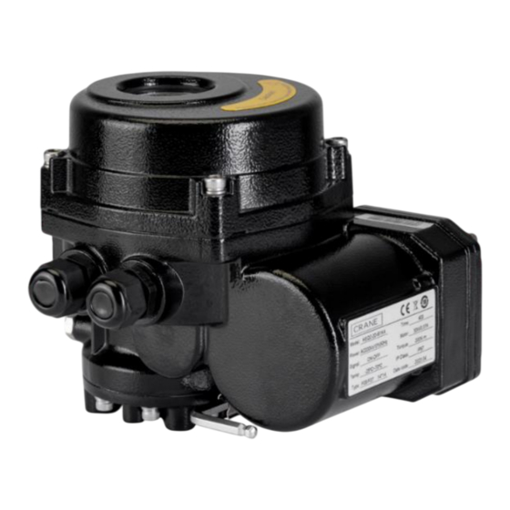
OVERVIEW
The ECQ range of Quarter Turn actuators offers
ge of Quarter Turn actuators offers compact design,
compact design, extended torque range, easy
ue range, easy installation, robust components,
installation, robust components, ensuring an
extended life span and safety features that
xtended life span and safety features that avoid
avoid operational hazards.
azards.
Optional features also expand the versatility of
res also expand the versatility of the actuator.
the actuator.
suitable for mounting on to specified Crane Fluid
Actuators are suitable for mounting on to
erfly Valves directly without the need for a spacer or
specified Crane Fluid Systems Butterfly Valves
directly without the need for a spacer or
mounting kit.
FEATURES / GENERAL SPECIFCATION
•
Power Supply: AC 1 phase – 220V +/- 10%,
GENERAL SPECIFCATION
50Hz / 60Hz
•
Enclosure: IP67 protection with anti-corrosion
r Supply: AC 1 phase – 220V +/- 10%, 50Hz / 60Hz
grade Epoxy polyester powder coating.
sure: IP67 protection with anti-corrosion grade Epoxy polyester powder coating.
•
Torque: ranges from 50Nm to 4000Nm
e: ranges from 50Nm to 4000Nm
Cycle On/Off: S2 - Max 15Min, S4 - 25%
•
Duty Cycle On/Off: S2 - Max. 60 Minutes,
S4 - 40%
Switches – 2x SPDT
ure Proof Space Heater.
•
Limit Switches – 2x SPDT
ent Temp -25
C to 70
0
•
Moisture Proof Space Heater.
ve Humidity - max 90%.
•
Ambient Temp -25°C to 70°C.
eat Protection: At 125
•
Relative Humidity - max 90%.
•
Overheat Protection: At 125°C, power cuts
off. When the motor cools, heat protection will
reset.
Page | 1
Page | 1
C.
0
C, power cuts off. When the motor cools, heat protection will reset.
0
INSTALLATION, OPERATING AND MAINTENANCE INSTRUCTIONS
INSTALLATION VIDEOS
Advertisement

Related Manuals for Crane ECQ1


Summary of Contents for Crane ECQ1
- Page 1 Optional features also expand the versatility of res also expand the versatility of the actuator. the actuator. suitable for mounting on to specified Crane Fluid Actuators are suitable for mounting on to erfly Valves directly without the need for a spacer or...
- Page 2 1 – 50Hz; 2 – 60Hz F – ON / OFF; M – MODULATING TORQUE RATING (LAST 4 DIGITS, E.G. 0050 = 50Nm; 0600 = 600Nm) ACTUATOR MODEL - ECQ1; ECQ2; ECQ3; ECQ4; ECQ5; ECQ4JS, ECQ5JS Rating Operating Time On/Off (s)
- Page 3 Installation & Maintenance should be carried out by competent personnel. If replacement • Ensure all wiring conforms to local codes, that parts are required, please contact Crane high and low voltage wiring is kept separated, BS&U. and when using multi-stranded wire, a cable ferrule is fitted to the cable end.
- Page 4 POSITION INDICATOR SIGHT GLASS the conduit from top to bottom and damaging • Crane does not recommend installation with MOUNTING FLANGE the electric drive. top works / actuator pointing downwards. Additional Guidance: •...
- Page 5 INSTALLATION, OPERATING AND MAINTENANCE INSTRUCTIONS MOUNTING INSTRUCTIONS Electric Actuator mounting to the Valve • Method 1 – With Valve in closed position: • Ensure the butterfly valve is in the fully closed position. ACTUATOR • Check the direction and position of the actuator shaft adapter is aligned so the pointer on the indication window is ‘0’...
- Page 6 INSTALLATION, OPERATING AND MAINTENANCE INSTRUCTIONS ACTUATOR WIRING INSTRUCTIONS Wiring diagram - Basic F – on/off type (Single Phase) Note: If space heater is connected as shown, this will be permanently on / live. Install external switch if intermittent use required. Wiring Diagram - Basic M-Modulating type (Single Phase) Note: If space heater is connected as shown, this will be permanently on / live.
- Page 7 INSTALLATION, OPERATING AND MAINTENANCE INSTRUCTIONS CABLE INSTALLATION AND WIRING REQUIREMENTS • Disassemble the Electrical Cover (Item 3 • Gently pull the cable to ensure that the as per parts diagram) by loosening the 4 cable cover seal positioned inside the socket head cap screws.
- Page 8 INSTALLATION, OPERATING AND MAINTENANCE INSTRUCTIONS CONFIGURATION AND SETTING – ON/OFF AND MODULATING Mechanical Limit Stop Setting • Power off the Actuator. The actuators are supplied as factory set with • Turn the valve disc to either fully closed / the expectation that no adjustment should be fully open position as required, using the required.
- Page 9 INSTALLATION, OPERATING AND MAINTENANCE INSTRUCTIONS • Move the actuator to the fully closed fully Electrical Travel Limit Cam Switches Setting open position using the actuator hand The actuators are supplied with expectation wheel. that no adjustment should be required to •...
- Page 10 INSTALLATION, OPERATING AND MAINTENANCE INSTRUCTIONS CONFIGURATION AND SETTING - MODULATING TYPE ONLY • During Local (Manual) Control mode, the Internal Digital Display / LED Display Indicators ‘Alarm LED’ is active. The Modulating version can be configured by • During valve opening action, the ‘Open accessing the Setting control panel.
- Page 11 INSTALLATION, OPERATING AND MAINTENANCE INSTRUCTIONS Local Control Operation / Remote Control Operation The valve / actuator can be operated by Local (Direct Manual) control of the actuator, or Remotely • Remote (Automatic) Control Operation (Automatically by system input signal, e.g. BMS. •...
- Page 12 INSTALLATION, OPERATING AND MAINTENANCE INSTRUCTIONS Input Signal switchover: 0-10V / 4-20mA INPUT FEEDBACK This Input Signal and Feedback signal can 20mA 20mA be configured with adjustment of x3 jumper 4-20mA 4-20mA 20mA switches located inside of Control Panel Cover 20mA 20mA (Item 4).
- Page 13 INSTALLATION, OPERATING AND MAINTENANCE INSTRUCTIONS Alarm / Fault Codes When a fault occurs, the alarm LED outputs information with other indicators as per the following: Alarm Status Fault code Fault information Alarm LED Remote LED Open LED Close LED Calibration error Flash 3 times Valve jammed Light solid...
- Page 14 INSTALLATION, OPERATING AND MAINTENANCE INSTRUCTIONS Feedback signal Output current trimming • Maximum control signal trimming (e.g. 20mA , 10V feedback) – ‘HF’ As a result of adjustment to various settings such as Mechanical and Electrical limit • Action the electric actuator to the open switches, or through general deviation of position, as per manual operation method.
- Page 15 INSTALLATION, OPERATING AND MAINTENANCE INSTRUCTIONS Failsafe mode in the event of break in Input • Press ‘A/M’ to be in Remote (Automatic) Control Signal Control mode. In the event of a break in the Input Control • Press ’▼’ for 10s, and the actuator will set to signal, the actuator can be set to then default to Normally Closed.
- Page 16 Every effort has been made to ensure that the information contained in this publication is accurate at the time of publishing. Crane Ltd assumes no responsibility or liability for typographical errors or omissions or for any misinterpretation of the information within the publication and reserves the right to change without notice.
Need help?
Do you have a question about the ECQ1 and is the answer not in the manual?
Questions and answers