Sanyo KHS0971 Technical & Service Manual
Dc inverter split system air conditioner
Hide thumbs
Also See for KHS0971:
- Technical & service manual (104 pages) ,
- Instruction manual (50 pages) ,
- Installation instructions manual (24 pages)
Advertisement
Quick Links
TECHNICAL & SERVICE MANUAL
KHS0971 + CH0971
KHS1271 + CH1271
DC INVERTER SPLIT SYSTEM AIR CONDITIONER
Indoor Model No.
KHS0971
KHS1271
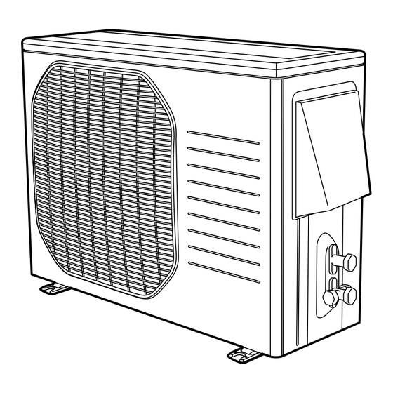
Indoor Unit
KHS0971
KHS1271
IMPORTANT
These air conditioners employ new
refrigerant R410A.
Pay special attention when
servicing the unit.
All manuals and user guides at all-guides.com
Product Code No.
1 852 099 79
1 852 099 80
Outdoor Model No.
Product Code No.
CH0971
1 852 330 21
CH1271
1 852 330 22
Outdoor Unit
CH0971
CH1271
REFERENCE NO.
FILE NO.
Destination: North America
SM
700647-06
Advertisement


Need help?
Do you have a question about the KHS0971 and is the answer not in the manual?
Questions and answers