Advertisement
Quick Links
Advertisement

Related Manuals for SevenStar D07-7B


Summary of Contents for SevenStar D07-7B
- Page 1 D07 - 7B 型 质量流量控制器 D07-7BM 型 质 量 流 量 计 使 用 手 册 版本 2011 . 12...
- Page 2 7.4 阀控操作注意 ……………………… 5.3 连接电缆插头……………………… 7.5 安装位置问题 ……………………… 5.4 与计算机或外部信号的连接……… 7.6 注意工作压差 ……………………… 5.5 调零和外调零……………………… 7.7 标定和不同气体的换算 …………… 6. 使用方法和操作步骤 ……………… 7.8 D07-7B,7BM 标准订单填写格式…… 6.1 质量流量控制器的操作…………… 8. 故障判断和处理 …………………… 6.1.1 开机操作………………………… 9. 保证、 保修与服务…………………… 6.1.2 清洗功能………………………… 9.1 产品保证和保修..…………………… 6.1.3 显示仪与计算机连接的操作……...
- Page 3 质量流量控制器和质量流量计 使 用 手 册 1. 使用须知 尊敬的用户, 感谢您购买本公司生产的 D07 系列质量流量控制器/质量流量计产品。 本 手册详细叙述了正确、安全使用该系列产品的必要事项。 产品使用者,请务必认真参阅本手册并理解后使用,在使用过程中,请注意带有 标 志的文字及注意事项中包含的所有内容。 对于未按照使用手册使用造成的财产损失或人身伤害,本公司有权不承担责任。 本手册对您安装、维护及故障维修时,必不可少,请妥善留存保管。 2. 用途和特点 质量流量计(Mass Flow Meter 缩写为 MFM) 用于对气体的质量流量进行精密测量;质 量流量控制器 (Mass Flow Controller 缩写为 MFC) 用于对气体的质量流量进行精密测量 和控制。它们在半导体和集成电路工业、特种材料学科、化学工业、石油工业、医药、环 保和真空等多种领域的科研和生产中有着重要的应用。其典型的应用场合包括: 电子工艺 设备, 如扩散、氧化、外延、CVD、等离子刻蚀、溅射、离子注入; 以及镀膜设备、光纤 熔炼、微反应装置、混气配气系统、毛细管测量、气相色谱仪及其它分析仪器。 D07 系列质量流量控制器和质量流量计具有精度高、重复性好、响应速度快、软启动、...
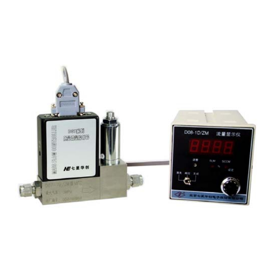
- Page 4 图 1.质量流量控制器与流量显示仪配套使用 第 2 页 共 26 页...
- Page 5 3. 主要技术指标 表 1. D07-7B 型 MFC 性能指标 D07-7B 型 编号 项 目 流量规格 ( 0~5,10,20,30,50,100,200,300,500) SCCM ( 0~1,2,3,5,10) ±1.5 % F.S 准确度 线性 ±1 % F.S ±0.2 %F.S 重复精度 10 sec 电特性: 响应时间 气特性: ≤ 4 sec 工作压差范围 (0.1 ~ 0.5) MPa 3 MPa 耐压...
- Page 6 表 2. D07-7BM 型 MFM 性能指标 D07-7BM 型 编号 项 目 ( 0~5,10,20,30,50,100,200,300,500) SCCM 流量规格 ( 0~1,2,3,5,10) ±1.5 % F.S 准确度 ±1 % F.S 线性 ±0.2 %F.S 重复精度 10 sec 响应时间 <0.01 MPa 气压降 3 MPa 耐压 5 ℃ ~ 45 ℃ 工作环境温度...
- Page 7 D 型插座 电路印制板 锁紧螺母 支架 电磁调节阀 调零电位器 传感器 进气接头 出气接头 流量通道 图 2. 7B 型质量流量控制器结构图 7BM 型流量计与 7B 型控制器相比,在结构上的不同点,就是少了电磁调节阀,其它 部分基本相同。 4.2 工作原理 流量传感器采用毛细管传热温差量热法原理测量气体的质量流量(无需温度压力补偿)。 将传感器加热电桥测得的流量信号送入放大器放大, 放大后的流量检测电压与设定电压进 行比较, 再将差值信号放大后去控制调节阀门, 闭环控制流过通道的流量使之与设定的流量 相等。分流器决定主通道的流量。与之配套的 D08 系列流量显示仪上设置有稳压电源, 3 位 半数字电压表, 设定电位器, 外设、内设转换和三位阀控开关等。本控制器与流量显示仪连 接后的工作原理如图 3 所示。 第 5 页 共 26 页...
- Page 8 +5.00V 流量显示仪 100.0 设定 (0 ~ +5.00V) 流量显示 设 定 内 外 +15V (0 ~ +5.00V) 流量检测 电源 ~220V 电 平 -15V 质量流量 控制器 质量流量计 比较器 +15V 放大器 关闭 阀控 驱动 传感器 清洗 -15V 调节阀 分流器通道 入口 出口 图 3. 质量流量控制器原理 控制器输出的流量检测电压与流过通道的质量流量成正比, 满量程(F.S)流量检测输出...
- Page 9 控制操作一般在流量显示仪上进行。当设定开关打到“内”设时, 由设定电位器控制流 量; 当打到“外”设时, 由用户提供的(0~+5)V 电压控制流量。 在显示面板上还设置有三位阀门控制开关, 当置“关闭”位时, 阀门关闭; 当置“清洗” 位时,阀门开到最大,以便气路清洗,或作为流量计使用;当置于“阀控”时,自动控制流量。 5. 安装和接线 5.1 外形及安装尺寸: 7B、7BM 各型号产品的外形和安装尺寸如图 4、图 5 所示。 图 4. D07-7B 型 MFC 外形图 第 7 页 共 26 页...
- Page 10 图 5. D07-7BM 型 MFM 外形图 注意 图中的高度 108mm 是不加电缆插头的高度,加上插头后的高度要再增加 50mm 左右。 5.2 气路接头形式 采用标准双卡套 (Swagelok)接头和 VCR 接头, 可提供 5 种尺寸接管外径的接头类型: a. Swagelokφ3 mm ; b. Swagelokφ6 mm ; 1/4" c. Swagelok (英制); 1/4" d. VCR (英制); 1/8" e. Swagelok (英制)。...
- Page 11 接头 前卡套 螺母 接管 后卡套 图 6. 双卡套接头安装示意图 注意 按图 6 所示安装接管时,在装上前卡套、后卡套、螺母后,先用手将螺母与接头拧紧, 再用扳手拧紧(国外进口的 Swagelok 接头要求用扳手旋转 1.25 圈拧紧 ,以保证不漏气。 注 意应该使用双扳手操作,用一只扳手卡住接头不动,用另一只扳手旋转螺母。特别是在拆卸 接管时必须使用双扳手操作,否则会引起接头松动,影响密封。 5.3 连接电缆插头 +15V 外调零 电源地 -15V -15V 设定 (0~+5V) -15V +15V 阀控 信号地 关闭 公共地 流量检测 +15V 地 清洗 -15V 图...
- Page 12 质量流量控制器通过专用电缆与配套流量显示仪连接后, 即可通电通气工作。 注意 D07-7B 型是 D07-7A 型产品的的升级换代型,7B 型采用了贴片元件,和国际标准的 D 型 插头。与 7A 型对照,插头引线功能的位置相同,但起始编号的方向相反。7B 型可以直接替 换 7A 型产品,7A 型原有的电缆可以直接插在 7B 型插座上工作,只是锁紧装置不一样,当然, 在替换时,通常应该连插头(或电缆)一起更换。 7BM 型质量流量计插座的接线见图 8, 7BM 型与 7B 的插座型号完全相同,只是在流 量计插件的接线中与控制器插件相比,少了“阀控”和“设定”两根线。 +15V 外调零 电源地 -15V -15V -15V 信号地 公共地 流量检测 +15V 地...
- Page 13 5.4 与计算机或外部信号的连接 a. 通过流量显示仪与计算机(或其它外部信号)的连接方法, 见图 9。 流量检测 A/D 转换输入 计算机 信号地 信号地 或 PLC 内设 外设 质量流量 D/A 转换输出 连接电缆 控制器 信号地 设定 +15V 或 阀控 关闭 质量流量计 流量显示仪 ( 注意: 质量流量计 -15V 无阀控线和设定线 ) 清洗 图 9. 通过流量显示仪与计算机的连接 若用户要检测流量输出信号(0V~+5V)时, 将线引至显示仪外控信号插座的 “流量检测” 和“信号地”(0 电平)线上即可,也可直接与计算机的模数(A/D)转换器连接,+5.00V 输出...
- Page 14 b. 流量计直接与计算机连接的接线方法,见图 10。 0~+5V 流量检测 A/D 转换输入 计算机 信号地 信号地 或 PLC 质量流量 0~+5.00V D/A 转换输出 设定 控制器 信号地 ( 注意: 质量流量计无阀控线和设定线 ) 或 阀控 阀控 质量流量计 +15V +15V 清洗 公共地 -15V 电源地 关闭 电源 +15V -15V -15V 图 10. 直接与计算机连接的接线方法 如果是...
- Page 15 线性 增益 调零 调零孔 图 11. 7B 和 7BM 型调节电位器位置图 本机还设计有外调零功能,当控制器与我厂新生产的(带外调零功能的)D08 系列流量 显示仪配套工作时,也可以通过显示仪面板上的调零电位器调零。但要注意,外调零的调 节范围比较小,若遇到较大的零点偏移,还需要调节控制器上的调零电位器,才能解决。 6. 使用方法和操作步骤(结合 D08 系列流量显示仪) 6.1 质量流量控制器的操作 6.1.1 开机操作 使用时主要操作在流量显示仪上进行(参见图 12)。 阀门控制开关及流量设定电位器在前 面板上,流量设定的内部或外部信号选择开关一般在后面板上。当设定选择开关打到“内” 时,用设定电位器设定流量,打到“外”时,由外部信号设定流量(参见流量显示仪的使 用说明书) 。 a. 阀开关处于“阀控”位时,先开气后开电源,则气体流量软启动经过约 20 秒钟达到原设定 值的 5%以内。一般应先将阀关闭,不通气,通电预热 15 分钟,待零点稳定以后再正式工 作。如果零点偏差较大,参见 5.5 条, 在不通气的情况下,可以通过调零电位器调零。 b.
- Page 16 d. 阀开关处于“阀控”位,并且设定不为零时,如果先开电源,后开气,则流量将会有一个大 过冲,然后迅速稳定至设定值。这种操作方法应当避免。 e. 先开电源、将阀开关置到“关闭”位,将设定值调到零,再开气,待预热至零点稳定后, 再转“阀控”位,然后将设定流量调至需要值, 则实际流量跟踪设定值而改变,无过冲。这 是最佳操作方法。 流量显示窗 流量单位指示 外调零电位器 设定电位器 阀控开关 图 12. 流量显示仪操作面板 6.1.2 清洗功能 欲用气体吹洗管路,可将阀开关置为“清洗”位, 清洗时的流量可达该控制器额定满量 程流量的几倍至几十倍。如果不通气,则根据需要可以抽真空以排除 MFC 内部及其上游残 存气体。然后将阀关闭,再开气,并转到“阀控”位工作。 6.1.3 显示仪与计算机连接的操作 参照图 1 和图 9,先将显示仪上的设定开关打到“外设”位,将阀控开关置于“阀控” 位,再启动计算机程序进行工作。 6.1.4 直接与计算机连接的操作。 参照图 1 和图 10,在流量计预热稳定以后,即可启动程序进行工作。 第 14 页 共 26 页...
- Page 17 6.1.5 阀控功能 当阀开关置于阀“控位”时, 用户也可通过外控信号插座上的“阀控”线控制阀门, (参 照图 3 和图 9),当阀控线接+15V 时,阀门关闭;当阀控线接-15V 时,阀门开到最大,处 于清洗状态;当阀控线悬空时,阀门处于自动控制状态。 6.1.6 关机操作 切断电源后,流量自动截止。最好先关气(将阀控开关置于“关闭”位和关闭气路中 的截止阀), 后断电源。 6.2 质量流量计的操作 6.2.1 开机预热: 使用前,先接通电源预热 15 分钟。 6.2.2 检查和调整零点 预热后, 检查流量计的零点(特别是在首次使用时), 参见 5.5 条, 在不通气的情况下, 可以通过调零电位器调零。 6.2.3 通气工作: 待零点稳定后, 即可通气工作。 注意观察气体流量, 最好不要超过满量程使用。 6.2.4 关机: 切断电源, 即停止流量计的测量工作, 不影响通道流过的气体流量。 7.
- Page 18 型质量流量控制器也可以选用聚四氟乙烯;当选用四氟乙烯时,阀口容易出现漏气,阀口 密封的漏气率小于满量程流量的 2%;对于使用特殊腐蚀性气体,所有密封材料都要作相应 改变。 注意 对于使用腐蚀性或有毒、易燃气体的产品,通气使用前应严格保证并检验安装和联接 的气密性;如需从系统上卸下,应在断开气路前,使用干燥的对人体无害的常规气体(如 氮气、空气)或惰性气体对产品进行彻底的清洗。如没有清洗,可能会引起火灾、爆炸、 中毒等意外事故,将导致人员伤亡。 7.3 阀口密封问题 质量流量控制器的电磁阀是调节阀, 不是截止阀, 不能当截止阀使用, 用户应另配截 止阀。特别是用户如果使用腐蚀性气体, 通常应该在质量流量控制器进出气口各加一个截 止阀, 以保证工作安全。 长期工作后, 如果控制器阀口的漏气率在 2%F.S 以内, 是属于正常 情况。如果漏气大于满量程的 2%, 则应进行维修。 7.4 阀控操作注意 在操作阀门进行“清洗”后,不得直接转至“阀控”位工作,必须先将阀门置至“关闭” 位,然后再转至“阀控”位工作。 7.5 安装位置问题 本流量计安装时最好保持安装面水平。 用户订货时应注明实际安装位置, 我公司根据用 户的安装位置进行标定后出厂。如果用户的实际安装位置与产品出厂时的标定位置不一致 时,产品可能出现零点偏移,此时可调整零点后再工作。 7.6 注意工作压差 对于质量流量控制器要特别注意工作介质的气压,...
- Page 19 于要求值,有可能流量达不到满量程值。 7.7 标定和不同气体的换算 本流量计出厂通常用氮气(N )标定。如果要求用使用气体标定, 需要在订货时与销售 人员特别申明。 用氮气标定的流量计用户使用其它气体时, 可以通过附录 10.1 的转换系数进行换算, 算出被使用气体的流量。将质量流量控制器显示出的流量读数,与某使用气体的转换系数 相乘,即得该被测气体在标准状态下的质量流量。 例如: 一个出厂标定为 100 SCCM(N ) 的 MFC, 通甲烷气体时显示的流量为 86 SCCM, 从附录 10.1 查得甲烷的转换系数为 0.719,则甲烷的实际流量为 86×0.719 即 61.8 SCCM。 如果用户使用混合气体,可以通过附录 10.2 介绍的方法, 计算出混合气体的转换系数。 第 17 页 共 26 页...
- Page 20 7.8 D07-7B、7BM 标准订单的填写格式 D07-[t] [g,g,g] [r,r,r,r] [f,f] 型号 – 质量流量控制器 - [7B ] - [7BM] 质量流量计 使用气体 [g,g,g] – 依照标准SEMI52-0302 例如: -[ 013 ] N -[ 007 ] H -[ 000 ] 混合气体详见 满量程流量 [r,r,r,r] – - [ 005C] 5SCCM...
- Page 21 -[ E ] 平躺安装 -[ U ] 进气口向上垂直安装 -[ D ] 进气口向下垂直安装 其它说明 – -[ - ] 出厂默认: 外罩及标签文字:中文 工作压差范围:D07-7B:(0.1 ~ 0.5) MPa (14.5~72.5 psid) D07-7BM:<0.01MPa (1.5psid) 耐压:3 MPa (435.1 psig) 标定温度:(22±2)℃ -[ S ] 特殊要求: 例如:外罩及标签文字:英文;特殊量程:9SLM;混合气体要注明比例: N (60%) + CO (40%);...
- Page 22 举例: 以D07-7B007001LCCNUS为例: D07-7B 007 001L CC N 型号:D07-7B MFC 使用气体: 满量程流量:1SLM 进出气接头: Swagelok 1/4" 密封材料: 氯丁橡胶(耐氨橡胶) 安装位置: 进气口向上垂直安装 特殊要求: 如 英文,工作压差(0.05~ 0.3) MPa,特殊接头(附图纸), 特殊标定温度40℃等要求逐一填写。 第 20 页 共 26 页...
- Page 23 8. 故障判断和处理 表 3. 故障判断和处理一览表 序 故 障 现 象 故 障 可 能 原 因 处 理 方 法 号 1.1 气源未开, 气路不通 接通气源, 开通气路 1.2 阀控开关关闭 将阀开关置于"阀控"位或"清洗"位 检查设定电位器和"内外"设定开关 开机后, 无气流 1.3 无设定信号 的状态等 流过 1.4 过滤器堵塞 *更换过滤器 1.5 调节阀故障 检查阀线包是否断, *清洗调节阀...
- Page 24 续表 3. 故障判断和处理一览表 序 故 障 现 象 故 障 可 能 原 因 处 理 方 法 号 5.1 气源压强太低或不稳 提高气源气压, 稳定气源压强 降低气源内阻 (大流量时要注意开 气流控制不稳定,有 5.2 气源内阻过大 大阀门, 加粗管道, 以至并联气瓶, 较大的波动 提高气源供气能力) 5.3 电路或调节阀故障 *维修调整 供电系统的地线和零线 检查接地系统, 注意一点接地 连接或机壳接地有问题 使用高频源时流量...
- Page 25 密封圈等)。 9.1.5 用户使用过有毒、有污染或腐蚀性气体的产品, 如果没有出示清除污染及净化处理的证明, 本公司将不负责修理或保修。 9.2 保修对使用的要求 a.气体必须洁净且没有颗粒物, 没有液体, 这就要求在MFC/MFM的上游气路中安装<30μm 的过滤器。 b.输入的气体压力必须符合产品的耐压标准, 不能超过该产品要求的最大压力。 c. 产品的使用气体必须与用户订货选择的密封材料相适应, 用户有责任按照可用的安全规章 使用每种气体。不正确的使用产品会使保修无效,由于不正确的使用所导致的损害不能 归咎于本公司。 d. 对电子线路的要求:必须小心按规定连接系统的接线, 不正确的接线会导致产品内部电路 板的永久损坏。若自备MFC电源, 需要电压波动小于5mV的高抗干扰稳压电源。 e. 气路的连接: 必须仔细的安装密封管件, 保证所有的密封管件经过单独检查并且没有划痕。 f.禁止自行拆开MFC/MFM。如果自行拆卸造成损坏,则本公司承诺的保修无效。 9.3 服务 本公司的产品工程师将会帮助您解决关于操作、标定、机电连接、工作条件要求、气体 转换等方面的问题。我们提供技术支持与维护, 提供产品的使用培训。 请您访问mfc.sevenstar.com.cn找到有关的产品资讯和离您最近的维修及服务中心。 第 23 页 共 26 页...
- Page 26 10. 附录 10.1 气体质量流量转换系数: 表 5. 气体质量流量转换系数表 密度(克/升 0℃) 气 体 代号 比热(卡/克℃) 转换系数 (SEMIE52-0302) 空气 0.2400 1.2930 1.006 氩气 0.1250 1.7837 1.415 砷烷 0.1168 3.4780 0.673 三溴化硼 0.0647 11.1800 0.378 三氯化硼 0.1217 5.2270 0.430 三氟化硼 0.1779 3.0250 0.508 硼烷 0.5020 1.2350 0.441...
- Page 27 续表 5. 气体质量流量转换系数表 密度(克/升 0℃) 气 体 代号 比热(卡/克℃) 转换系数 (SEMIE52-0302) 锗烷 0.1405 3.4180 0.569 氢气 3.4224 0.0899 1.010 溴化氢 0.0861 3.6100 1.000 氯化氢 0.1911 1.6270 1.000 氟化氢 0.3482 0.8930 1.000 碘化氢 0.0545 5.7070 0.999 硫化氢 0.2278 1.5200 0.844 氦气 1.2418 0.1786 1.415...
- Page 28 10.2 转换系数使用说明 质量流量控制器、质量流量计出厂时一般用 N 标定,实际使用中如果是其它气体,必 要时可进行读数修正,方法是以流量显示仪显示的流量乘以流量转换系数。如是单组份气 体, 其转换系数可在我厂产品技术说明书中查得; 如是多组份气体 (假定由 n 种气体组成) , 请按下列公式计算其转换系数 C: 基本公式: C=0.3106 N /ρ(Cp) 其中: ρ——为气体在标准状态下的密度 CP——为气体的定压比热 N ——为气体分子构成系数(与该气体分子构成的组份有关, 见下表) 气体分子构成系数表: 气体分子构成 举 例 N 取 值 单原子分子 1.01 1.00 双原子分子 0.94 三原子分子 0.88 多原子分子 ω...
- Page 29 北京 741 信箱 3 分箱 邮政编码: 100015 联系电话: +86-10-64362939 64362925 +86-10-64361831—8491/8315 传 真: +86-10-64362923 网 址: http://mfc.sevenstar.com.cn 电子信箱(E-mail): mfcsales@sevenstar.com.cn 乘车路线: 乘地铁到东直门, 换乘 401 路公共汽车,到陈各庄下车或 乘地铁到农业展览馆,换乘 516 路公共汽车,到酒仙桥东路北口下车 *公司承诺不断提升产品品质,保 上海办事处: 上海闸北区天目西路 547 号联通国际大厦 1916 室(200070) 留在不经通知的情况下对此手册 电 话: +86-21-33030324 传 真: +86-21-63533265 所含信息进行修改的权力。...
- Page 30 D07-7B / ZM Mass Flow Controller D07-7BM / ZM Mass Flow Meter INSTRUCTION MANUAL Version Dec. 2011...
- Page 31 SEVENSTAR may not be responsible. If you require any additional information or assistant of Sevenstar D07 series Mass Flow Controller and Mass Flow Meter, please feel free to contact your local Sevenstar Sales Agent or Sevenstar Customer Service at: (8610)- 6436 2925.
- Page 32 6.5 Installation Position ………………....4.5 PC Connections……………………………... 6.6 Operation Pressure Resistance………………. 4.6 Zero Adjustment……………………………. 6.7 Calibration and Conversion………………….. 5. OPERATION INSTRUCTIONS………….. 6.8 D07-7B, 7BM Ordering Code……………… 5.1 MFC Operation…………………………….. 7. TROUBLESHOOTING…………………….. 5.1.1 Start Up…………………………………… 8. WARRANTY & SERVICE………………….. 5.1.2 Purge………………………………………...
- Page 33 Operating Manual 1. APPLICATION & FEATURES Mass Flow Meter (MFM) accurately measures mass flow rates, Mass Flow Controller (MFC) accurately measures and controls mass flow rates despites gas volume fluctuated due to pressure or temperature changes. Which is widely applied in the fields as: semiconductor and IC fabrication, special materials science, chemical industry, petrolic industry, pharmaceutical industry, environmental protecting and vacuum system researching, etc..
- Page 34 2. SPECIFICATION Table 1.Specifications of D07-7B Item D07-7B Ranges of Flow ( 0~5,10,20,30,50,100,200,300,500) SCCM ( 0~1,2,3,5,10) Accuracy ±1.5 % F.S Linearity ±1 % F.S Repeatability ±0.2 %F.S Response-Time Electronic characteristic: 10 sec (0~100%) Gas characteristic: ≤ 4 Operation Pressure (0.1 ~ 0.5) MPa...
- Page 35 Power supply -15 V 50 mA According to Figure 5 Dimensions Weight 0.92 kg The main specifications of D07 series could be found in table 1 and table 2. D07-7BM is the measuring part of D07-7B. Page 3 of 27...
- Page 36 Inlet-Fittings Outlet-Fittings Base Figure 2. Structure of D07-7B Structure of D07-7M is basically as same as structure of D07-7A except solenoid valve. 3.2 Operation Principle The flow sensor that measure the mass flow (it don’t need pressure compensation) is a kind of capillary pipe temperature difference flow sensor which consists of two dependent resistors winding on the thin-wall capillaries.
- Page 37 signal which is proportional to the mass flow rate of the gas through the tube. This 0~5 VDC signal is compared to a set point voltage from a D08 series Flow Readout Box (or other voltage source). From this comparison, any deviation between set point signal and measured signal are chapleted into a control valve adjustment until two signals are identical.
- Page 38 Attention : When Valve controller of MFC is posited on PURGE, it can be used as a MFM. When it is used as a MFM, the flow test voltage can reach beyond +10V, but it is important, if the flow is beyond F.S. (Full Scale), flow will not have linearity relation with test voltage.
- Page 39 Check that the delivery is complete and no parts are missing. Since the D07-7B can be ordered in Several configuration, ensure that the scope of supply is corect. If you think there is a problem plase contact the forwarder at once, with regard to liability.
- Page 40 Figure 5. Dimension of D07-7BM/ZM Attention : The height of 108mm is the height without electric connector of cable. The height will be added 50mm more after added the electric connector. 4.3 Fittings The standard fittings are used Swagelok and VCR, there are five type’s fittings can be provided: a.
- Page 41 4.4 Electrical Interfacing +15V Zero adjustment Power common -15V -15VDC Set(0~5VDC) +15V -15VDC Valve drive Signal common Auto Common Output(0~5VDC) Purge +15VDC -15V Figure 7. D07-7B Electrical Interfacing Page 9 of 27...
- Page 42 Box. 7B-MFC connection is showing in the following figure 7. Attention : D07-7B is upgrade of D07-7A; D07-7B applied affixed components and international standard D connector. Compared with 7A, they have the same position of connector lead but opposition of serial numbers.
- Page 43 4.5 PC Connections a. Connection through Flow Readout Box with PC or other external signal. (Figure 9) Flow Signal Output A/D In COMPUTER Signal common Signal common Or PLC D/A Out Connection MFC or Signal common Cable +15V Off Valve drive (ATTENTION: No “Valve drive”...
- Page 44 b. PC Directly Connection (Figure 10) 0~+5V Flow Signal Output A/D In Signal common Signal common PC or PLC 0~+5.00 D/A Out Signal common MFC or MFM (ATTENTION: No “Valve drive” and “Set” in MFM ) Auto Valve drive +15V +15V Purge common...
- Page 45 the ranges of external zero adjustment is narrow, when there is big zero excursion happened, it should be better adjust zero from zero potentiometer of MFC. Linearity potentiometer Zero Span potentiometer Zero potentiometer Figure 11. The Position of Potentiometer of 7B & 7BM Another way to adjust zero is potentiometer adjustment from D08 series Flow Readout box.
- Page 46 5. OPERATING INSTRUCTIONS 5.1 MFC Operation 5.1.1 Start Up (Figure 12) The main operating should perform in the Flow Readout Box. Valve Control Switches and flow setting potentiometer are in the front of Readout Box panel, the flow setting internal or external signal control switches are on the back of panel of Readout Box.
- Page 47 c. If Valve switch is on the position of PURGE, the flow rate will reach up to the maximum value after gas and power supplying, which will have the function of air blasting to the gas circuit. d. If Valve switch is on the position of AUTO and presetting is not zero, open the gas after power supply, the flow rate will have a big overshoot and then rapidly reach to the stable presetting value, this kind of operation should better be avoided.
- Page 48 Please check up zero point of MFM after its warming up (especially for the first time operating), it could have reference in 4.5, without gas supplying, which could adjust zero by zero potentiometer. 5.2.3 Gas Supply After zero movement reaches stable, MFM Could have gas supply. Please pay attention to the flow rate, it should be better operate not beyond full scale range.
- Page 49 6. CAUTION 6.1 Medium Forbidden The gas of using should be purified without dust、 liquid and oil stain. When necessary, it should be added filter to gas circuit to make sure gas purification. If the outlet of MFC connects with liquid sources, which should be added simple directional valve of MFC outlet to avoid the liquid is refluent to the tube to destroy MFC.
- Page 50 6.6 Pressure Resistance Please be caution for the medium operating pressure of MFC, it should not be beyond the rage of specification of inlet and outlet. Especially while operating under the high-pressure situation, the big differential pressure will affect flow fail to shut off or lower adjustment. In case of using heavy flow rate of MFC, please be sure appropriately widen tube and reduce gas internal resistance, if operating differential pressure is lower than the value of request, it might could not be reach to the full scale flow rate value.
- Page 51 6.8 D07-7B, 7BM Ordering Code D07-[t] [g,g,g] [r,r,r,r] [f,f] [s] [m] Type Number – - [7B ] - [7BM] [g,g,g] – Please consult SEMI52-0302 For Example: -[ 013 ] N -[ 007 ] H -[ 000 ] Mixture gases (please consult [d] for detail)
- Page 52 -[ D ] Vertical Inlet Down Description – -[ ] Default Value: The letters on cover and tag:in Chinese Differential Pressure:D07-7B: (0.1 ~ 0.5) MPa (14.5~72.5 psid) D07-7BM:<0.01MPa (1.5psid) Max Operating Pressure: 3 MPa (435.1 psig) Calibration Temperature:(22±2)℃ -[ S ] Customer Special Requirements:...
- Page 53 Type Number:D07-7B MFC Gas:H Flow Range Full Scale:1SLM Inlet and Outlet Fittings:Swagelok 1/4" Seal Materials: NEOPRENE Mounting Position:Vertical inlet up Customer Special Requirements:For Example:The letters on cover and tag:in English;Differential Pressure:(0.05~0.3) MPa; Customer Special fittings(According to drawing) ;Customer Special Calibration Temperature:40℃.
- Page 54 7. TROUBLESHOOTING Table 3. Failure Handling FAILURE CAUSE TREATMENT There is no gas flow 1.1 Gas flow is shutting off, no gas Check the gas sourcing and make it after turn on. inputting open 1.2 Valve control switch is shutoff Turn the switch to CONTROL or PURGE 1.3 No setting signal...
- Page 55 FAILURE CAUSE TREATMENT Fluctuant flow rate Inlet pressure is too low or Heighten inlet pressure instable 5.2. High internal gas resistance Lessen internal resistance (The heavy gas flow should have big valve open, widen tube to parallel connecting gas bottles to improve gas supply capacity.) 5.3 Circuit or valve failure *Repair and adjust Disturbed...
- Page 56 Buyers undertake to check and inspect the goods and to notify SevenStar of shipment incidents by fax, phone or e-mail as soon as possible after receipting the goods.
- Page 57 9. APPENDIX 9.1 Mass Flow Conversion Factors Table 4. Conversion Factors GAS CODE HEAT ρ Factors (SEMIE52-0302) ( Cal/g ℃ (g/l 0 ) ℃ 0.2400 1.2930 1.006 0.1250 1.7837 1.415 0.1168 3.4780 0.673 0.0647 11.1800 0.378 0.1217 5.2270 0.430 0.1779 3.0250 0.508 0.5020...
- Page 58 Continue To Table 4. Conversion Factors GAS CODE HEAT ρ Factors (SEMIE52-0302) ( Cal/g ℃ (g/l 0 ) ℃ 0.1405 3.4180 0.569 3.4224 0.0899 1.010 0.0861 3.6100 1.000 0.1911 1.6270 1.000 0.3482 0.8930 1.000 0.0545 5.707 0.999 0.2278 1.5200 0.844 1.2418 0.1786 1.415...
- Page 59 9.2 Conversion Factors Instruction MFC and MFM are standard calibrated by N while it’s out of factory. Other gas calibrations can be approximated by converting of conversion factors of our instruction. While using other gas operating: One single gas: The conversion factors could find out in the users specification instruction. A mixture of two or more gases: Assume there is “n”...
- Page 60 Beijing Sevenstar Qualiflow Electronic Equipment Manufacturing Co.,Ltd. D07 Series Mass Flow Controller Beijing Sevenstar Electronics Co., Ltd Mass Flow Meter Subsidiary Co., Ltd Address: No.1 Jiuxianqiao East Rd., Chaoyang District, Beijing, China P.O.BOX 3#741, Beijing, China Post code: 100015 Tel:...
Need help?
Do you have a question about the D07-7B and is the answer not in the manual?
Questions and answers