Advertisement
Quick Links
Corelis NetUSB-1149.1
JTAG Boundary Scan Controller
A l l t r a d e m a r k s , b r a n d n a m e s , a n d b r a n d s a p p e a r i n g h e r e i n a r e t h e p r o p e r t y o f t h e i r r e s p e c t i v e o w n e r s .
• C r i t i c a l a n d e x p e d i t e d s e r v i c e s
• I n s t o c k / R e a d y - t o - s h i p
Artisan Scientific Corporation dba Artisan Technology Group is not an affiliate, representative, or authorized distributor for any manufacturer listed herein.
In Stock
Used and in Excellent Condition
Open Web Page
https://www.artisantg.com/73898-1
• We b u y y o u r e x c e s s , u n d e r u t i l i z e d , a n d i d l e e q u i p me n t
• F u l l - s e r v i c e , i n d e p e n d e n t r e p a i r c e n t e r
Advertisement

Related Manuals for Corelis USB-1149.1/E

Summary of Contents for Corelis USB-1149.1/E
- Page 1 Corelis NetUSB-1149.1 JTAG Boundary Scan Controller In Stock Used and in Excellent Condition Open Web Page https://www.artisantg.com/73898-1 A l l t r a d e m a r k s , b r a n d n a m e s , a n d b r a n d s a p p e a r i n g h e r e i n a r e t h e p r o p e r t y o f t h e i r r e s p e c t i v e o w n e r s .
- Page 2 CORELIS USB-1149.1/E USB-1149.1/E High-Speed USB Port Boundary-Scan Controller User’s Manual USB-1149.1/E User's Manual, P/N 70345 REV I Copyright 2003-2007 Corelis Inc. 12607 Hidden Creek Way Cerritos, CA 90703-2146 Telephone: (562) 926-6727 • Fax: (562) 404-6196...
- Page 4 All rights reserved. No part of this document may be reproduced or translated to other languages without the prior written consent of CORELIS. CORELIS assumes no responsibility for the use of or reliability of its software on equipment that is not furnished by CORELIS.
- Page 5 PRODUCT WARRANTY This CORELIS product has a warranty against defects in material and workmanship for a period of 90 days from date of shipment. During the warranty period, CORELIS will, at its option, either repair or replace products that prove to be defective.
- Page 6 Hardware Installation..........................2-2 CHAPTER 3 CONNECTING TO THE TARGET........3-1 Connecting to the Target..........................3-1 Target Connector Pin Assignments......................3-2 CHAPTER 4 USING USB-1149.1/E WITH SCANEXPRESS ....4-1 Hardware Setup............................4-1 Using USB-1149.1/E with ScanExpress Tools..................4-1 CHAPTER 5 THIRD PARTY APPLICATION INTERFACE......5-1 Using USB-1149.1/E with ScanExpress Runner Command-line ..............5-1 APPENDIX A RECOMMENDED TARGET CONNECTORS ....
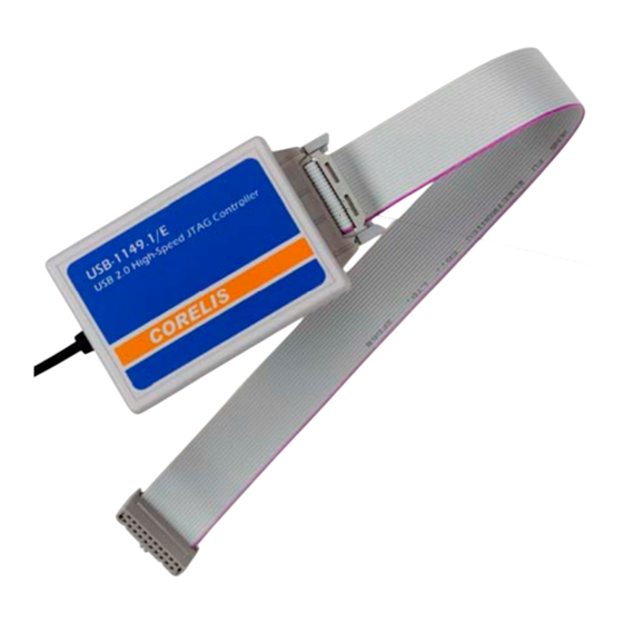
- Page 7 Table of Figures Figure 1-1. The Corelis USB-1149.1/E Boundary-Scan Controller................. 1-1 Figure 1-2. Minimal Test Access Port (TAP) ......................1-3 Figure 2-1. Found New Hardware Wizard (WinXP)....................2-3 Figure 2-2. Found New Hardware Wizard (WinXP)....................2-3 Figure 2-3. Windows Logo Warning Dialog (WinXP) ..................... 2-4 Figure 2-4.
- Page 8 Table 3-4. EJTAG Compatible Cable 15425 TAP Connector Pin Assignments ............3-5 Table 3-5. ARM compatible USB-1149.1/E, Model 10341, TAP Connector Pin Assignments......... 3-6 Table 3-6. Power PC Compatible USB-1149.1/E, Model 10346, TAP Connector Pin Assignments......3-7 Table 5-1. USB-1149.1/E Controller Parameters ....................5-1 Table A-1.
- Page 10 PC equipped with a USB2.0 (or USB1.1) port and any IEEE Standard 1149.1 compatible target. The USB-1149.1/E is designed to control the operation of an IEEE Standard 1149.1 boundary-scan (JTAG) test access port (TAP) by generating the proper signals under software control to interface with the target device.
- Page 11 The USB-1149.1/E is often used to perform microprocessor emulation via the device JTAG port. It is used for firmware development providing single-step, break, and content update/visibility access. There are several versions of this product, which are optimized for various families of targets, providing enhanced large data block download and upload mechanisms for these respective devices.
- Page 12 Figure 1-2. Minimal Test Access Port (TAP) Features of the USB-1149.1/E The Corelis USB-1149.1/E is a sophisticated test controller that can access devices, boards or systems compliant with IEEE Standard 1149.1. The USB version 2.0 port compatible module supports one JTAG boundary-scan chain (TAP). In addition, three general purpose, bi-directional discrete I/O signals can test or control non-boundary-scan areas of the unit under test (UUT).
- Page 13 (excluding low speed). Speed adjustment is automatic per the standard. This host port also supplies the power to operate the USB-1149.1/E. The hot plug-in/out feature of this standard is fully supported. The user simply plugs it into a PC USB socket, and it is auto-sensed as ready-to-scan.
- Page 14 Programmable Clocks The USB-1149.1/E’s programmable TCK output to the IEEE Standard 1149.1 compatible target system can be configured over a wide range of frequencies, using on-board clock generation circuitry. A programmable Phase Locked Loop (PLL) enables both a wide range and fine selection resolution.
- Page 15 Target Interface Signal DC Characteristics Symbol Test Conditions Limit Min Limit Max Units Vdd Adjust >= 2.7 V Vdd + 0.5 Vdd Adjust < 2.7 V 0.65 × Vdd Vdd + 0.5 Vdd Adjust >= 2.7 Vdd Adjust <= 2.0 0.35 ×...
- Page 16 Power Requirements provided via the USB cable in compliance with specification Operating Environment Temperature 0C to 55C Relative Humidity 10% to 90%, non condensing Storage Environment Temperature -40C to 85C Product Overview...
- Page 18 Ensure all materials listed are present and free from visible damage or defects before proceeding. If anything appears to be missing or damaged, contact Corelis at the number listed on the front cover immediately. The following optional target interface cables are also available from Corelis: ...
- Page 19 Add/Remove Hardware Wizard (that will automatically show up when you use Windows 2000 or Windows XP operating system) and install the ScanExpress Applications from the CD. The next time you start the PC and plug in the USB-1149.1/E, Windows will automatically recognize and configure the USB-1149.1/E.
- Page 20 Figure 2-1. Found New Hardware Wizard (WinXP) The following dialog box as shown in Figure 2-2 will pop up. Select “Install the software automatically (Recommended)” and click on the Next button. Figure 2-2. Found New Hardware Wizard (WinXP) USB-1149.1/E Installation...
- Page 21 Figure 2-3. Windows Logo Warning Dialog (WinXP) After the necessary files are copied to the system, the following dialog box, Figure 2-4, will pop up indicating that the device driver is successfully installed. Figure 2-4. Installation Successfully Completed (WinXP) USB-1149.1/E Installation...
- Page 22 Figure 2-5. Found New Hardware Wizard (WinXP) The following dialog box as shown in Figure 2-6 will pop up. Select “Install the software automatically (Recommended)” and click on the Next button. Figure 2-6. Found New Hardware Wizard (WinXP) USB-1149.1/E Installation...
- Page 23 After the necessary files are copied to the system, the following dialog box, Figure 2-8, will pop up indicating that the device driver is successfully installed. Click on the Finish button to complete the driver installation. Figure 2-8. Installation Successfully Completed (WinXP) USB-1149.1/E Installation...
- Page 24 The installation of the device drivers is now completed. Verify that the USB-1149.1/E was correctly installed by checking for its entry in the Windows Device Manager. To run the Device Manager, right mouse click on the My Computer icon and then select Properties.
- Page 26 The connection to the user target (UUT) board/system is done using the TAP cable that connects to the 20 pin connector on the USB-1149.1/E box on the opposite side of the USB cable. To connect the TAP cable connector to the target (UUT) follow these steps in the order listed: Verify that the target power is OFF.
- Page 27 Target Connector Pin Assignments The following tables enumerate the pinout of the TAP connector for each of the USB-1149.1/E target cables. Signal Direction USB-1149.1/E side termination TRST* Input to the UUT 33 ohm series Input to the UUT 33 ohm series Output from the UUT 4.7K pull-up...
- Page 28 Signal Direction USB-1149.1/E side termination TRST* Input to the UUT 33 ohm series Input to the UUT 33 ohm series Output from the UUT 4.7 pull-up Input to the UUT 33 ohm series Input to the UUT 33 ohm series DISCR0 (external write*) Input to the UUT (also general I/O) 4.7K pull-up...
- Page 29 Signal Direction USB-1149.1/E side termination TRST* Input to the UUT 33 ohm series Input to the UUT 33 ohm series Output from the UUT 4.7k ohm pull-up Input to the UUT 33 ohm series Input to the UUT 33 ohm series Table 3-3.
- Page 30 Signal Direction USB-1149.1/E side termination TRST* Input to the UUT 33 ohm series Input to the UUT 33 ohm series Output from the UUT 4.7k ohm pull-up Input to the UUT 33 ohm series Input to the UUT 33 ohm series DISCR0 (external write*) Input to the UUT (also 4.7k ohm pull-up...
- Page 31 Signal Direction USB-1149.1/E side termination Not connected Not connected TRST* Input to the UUT 33 ohm series Input to the UUT 33 ohm series Input to the UUT 33 ohm series Input to the UUT 33 ohm series Not connected Output from the UUT 4.7k ohm pull-up...
- Page 32 Signal Direction USB-1149.1/E side termination Output from the UUT 4.7k ohm pull-up Input to the UUT 33 ohm series TRST* Input to the UUT 33 ohm series Not connected Not connected Input to the UUT 33 ohm series Not connected...
- Page 34 ScanExpress Debugger or ScanExpress Programmer is done in a similar fashion. Make sure that USB-1149.1/E controller is plugged in to your PC. Wait 3 to 5 seconds before starting ScanExpress Applications if you just plugged in the controller.
- Page 35 Select the USB-1149.1/E controller from the icons on the left. Adjust the settings to the desired values. After you have made your selections, click on the Apply button to test and save the settings. When the program saves the settings successfully, it displays the controller in the Current Controller box.
- Page 36 ADO), and then terminate. The following table shows the controller identifiers and associated parameters. Consult the ScanExpress Runner User’s Manual for more detail. The USB-1149.1/E controller uses 3 parameters. The parameters are described in the table below. Controller keyword: USB-1149.1/E...
- Page 37 3.0 Clock Delay Table 5-1. USB-1149.1/E Controller Parameters (continued) Example: To select a USB-1149.1/E controller with a TAP voltage of 3.30 V, TCK frequency of 1 MHz, and automatic delay compensation, use this “controller specification” string: -controller “USB-1149.1/E,42,113,1,,,,” Third Party Application Interface...
- Page 38 Boundary-scan based test equipment, such as the Corelis ScanExpress family of products, utilize a single TAP to interface to the UUT. This section explains how to implement a simple TAP connector that is compatible with most standard test equipment.
- Page 39 Table A-1 describes the 10 pin TAP connector signals and Corelis recommended values of terminating resistors: Signal Direction Termination TRST* Input to the UUT 1K pull-up (or 1.5K pull-down) Note: Some target boards may require a pull-down resistor on Input to the UUT...
- Page 40 Figure A-2 shows a typical schematic of the target TAP connector with the recommended termination resistors. The 1K pull-up resistors should connect to the target Vcc supply corresponding to the interface voltage (programmable on the USB-1149.1/E from 1.25 to 3.3 V). Recommended resistor values are +/- 5%. Target Board...
- Page 41 16-pin Flash Programming TAP Connector To build in support for in-circuit programming of flash or microprocessor devices, Corelis recommends including supplemental control signals in the TAP interface. The ScanExpress Programmer can use a 16-pin TAP, similar to Figure A-3, to improve programming time. This interface adds Write_Strobe*, Ready/Busy*, and ground signals to the standard 5-signal interface.
- Page 42 Part Number Flash TAP Straight header, 16-pin, 4 wall, with center notch 2516-6002UG Table A-3. Flash Programming TAP 16 Pin Connector Table A-4 describes the signals and Corelis recommended values of terminating resistors: Note: Some target Signal Direction Termination boards may require a...
- Page 43 Figure A-4 shows a typical schematic of the target TAP connector with termination resistors. The 1K pull-up resistors should connect to the target Vcc supply corresponding to the interface voltage (programmable on the USB-1149.1/E from 1.25 to 3.3 V). Recommended resistor values are +/- Vcc Vcc...
- Page 44 The 20-pin TAP connector is an enhanced 16-pin connector, with all seven 16-pin TAP signals, plus two additional signals and grounds for Corelis ScanTAP intelligent pod products. These two signals serve additional functions such as power monitoring / power short testing. However, USB- 1149.1/E controller does not support power monitoring / power short testing.
- Page 45 Note: Some target Signal Direction Termination boards may require a pull-down resistor on the TRST* Input to the UUT 1K pull-up TRST* signal to assure normal device operations when not in boundary- Input to the UUT 1K pull-up scan test mode Note: The target TDI Output of the UUT 33 ohm series...
- Page 46 Figure A-6 shows a typical schematic of the target TAP connector with termination resistors. The 1K pull-up resistors should connect to the target Vcc supply corresponding to the interface voltage (programmable on the USB-1149.1/E from 1.25 to 3.3 V). Recommended resistor values are +/- Vcc Vcc Vcc Vcc Vcc Vcc Vcc...
- Page 48 Self Test Utility Software The USB-1149.1/E has a self test utility that can be used to test the unit and make sure that it is fully functional. Logic at the TAP connectors can read back data shifted out on TMS and TDO synchronously with the TCK.
Need help?
Do you have a question about the USB-1149.1/E and is the answer not in the manual?
Questions and answers