Table of Contents
Advertisement
Quick Links
Advertisement
Table of Contents

Related Manuals for Corelis NetUSB-1149.1

Summary of Contents for Corelis NetUSB-1149.1
- Page 1 Artisan Technology Group is your source for quality new and certified-used/pre-owned equipment SERVICE CENTER REPAIRS WE BUY USED EQUIPMENT • FAST SHIPPING AND DELIVERY Experienced engineers and technicians on staff Sell your excess, underutilized, and idle used equipment at our full-service, in-house repair center We also offer credit for buy-backs and trade-ins •...
- Page 2 High-Speed LAN/USB2.0 Boundary-Scan Controller User’s Manual Document Part Number: 70337 REV L Copyright © 2004 - 2008 Corelis Inc. 13100 Alondra Blvd. Suite 102 Cerritos, CA 90703-2262 Telephone: (562) 926-6727 • Fax: (562) 404-6196 Artisan Technology Group - Quality Instrumentation ... Guaranteed | (888) 88-SOURCE | www.artisantg.com...
- Page 3 Artisan Technology Group - Quality Instrumentation ... Guaranteed | (888) 88-SOURCE | www.artisantg.com...
- Page 4 CORELIS. CORELIS assumes no responsibility for the use of or reliability of its software on equipment that is not furnished by CORELIS. The firmware inside the NetUSB-1149.1 includes compiled source code licensed from the Free Software Foundation.
- Page 5 For assistance, contact your nearest Corelis Sales and Service Office. RETURN POLICY No items returned to CORELIS for warranty, service, or any other reason shall be accepted unless first authorized by CORELIS, either direct or through its authorized sales representatives. All returned items must be shipped pre-paid and clearly display a Returned Merchandise Authorization (RMA) number on the shipping carton.
-
Page 6: Table Of Contents
CHAPTER 4 USING NETUSB-1149.1 WITH SCANEXPRESS ........4-1 Hardware Setup ............................4-1 Using NetUSB-1149.1 Family with ScanExpress Tools over a Network Connection ......4-1 Using NetUSB-1149.1 Family with ScanExpress Tools over a USB Connection ........4-3 CHAPTER 5 THIRD PARTY APPLICATION INTERFACE ......... 5-1 Using NetUSB-1149.1 with ScanExpress Runner Command-line ............ - Page 7 Artisan Technology Group - Quality Instrumentation ... Guaranteed | (888) 88-SOURCE | www.artisantg.com...
- Page 8 Figure B-1. Self-Test Results for the NetUSB-1149.1/E and the NetUSB-1149.1/SE ..........B-1 Figure B-2. Self-Test Part A Results for the NetUSB-1149.1/E or the NetUSB-1149.1/SE ........B-2 Figure B-3. Self-Test Part B Results for the NetUSB-1149.1/E or the NetUSB-1149.1/SE ........B-3 Figure C-1.
- Page 9 Table 1-1. Model Descriptions ..........................1-2 Table 1-2. Programmable TCK Frequencies......................1-7 Table 1-3. NetUSB-1149.1 SCSI Direct TAP Target Interface DC Characteristics ..........1-9 Table 1-4. NetUSB-1149.1/E TAPs Target Interface DC Characteristics .............. 1-10 Table 1-5. NetUSB-1149.1/SE TAPs Target Interface DC Characteristics ............1-10 Table 1-6.
-
Page 10: Chapter 1 Product Overview
JTAG port. This facilitates firmware development by providing single- step, break, and content update/visibility access. There are three models of this product. The basic NetUSB-1149.1 (no /E or /SE suffix) has scanning access through a single SCSI II 68-pin connector. This supports a single direct target TAP operation with the appropriate cable. -
Page 11: Figure 1-1. The Corelis Netusb-1149.1 Boundary-Scan Controller
The versions offered at the time of this publication are shown in Table 1-1 below. Model Description Scan Connector 10338 NetUSB-1149.1, direct TAP or remote pod ScanExpress port 68-pin SCSI II four 20-pin TAP 10337A NetUSB-1149.1/E, four built-in TAP ports... -
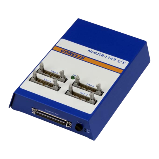
Page 12: Figure 1-2. The Corelis Netusb-1149.1/E Boundary-Scan Controller
Figure 1-2. The Corelis NetUSB-1149.1/E Boundary-Scan Controller Figure 1-3. The Corelis NetUSB-1149.1/SE Boundary-Scan Controller Product Overview Artisan Technology Group - Quality Instrumentation ... Guaranteed | (888) 88-SOURCE | www.artisantg.com... -
Page 13: What Is Ieee Standard 1149.1
(UUT) target. They facilitate non-scanned target FLASH write pulsing and FLASH ready/busy line sensing to greatly reduce the scanning cycles required for such devices. With its software- controlled voltage translating logic, the NetUSB-1149.1 family can test low voltage as well as standard TTL/CMOS systems. -
Page 14: Adjustable Voltage Interface
1.25 V and 3.30 V with 0.05V resolution . Discrete Input/Output Signals SCSI Connector Direct TAP Port The NetUSB-1149.1 family offers 3 discrete input and 5 discrete output signals on the SCSI connector (front panel). They are driven or sensed under host software control, in coordination with the scanning operation. -
Page 15: Usb Port Interface
Ethernet Port Interface This serves as an alternate host access point to the USB interface. The NetUSB-1149.1 family Ethernet interface supports 10/100baseT with automatic speed switching. It is IEEE 802.3u 100BASE-FX compatible. -
Page 16: Programmable Clocks
30 feet in length, with no additional hardware, at full TCK rate performance. The 8 TAPs of the NetUSB-1149.1/SE, the 4 TAPs of the NetUSB-1149.1/E, or the remote pod TAPs driven by the NetUSB-1149.1 can be programmed to daisy-chain sub-sets of the TAP ports into single chains. -
Page 17: Specifications
68-pin SCSI II type (AMP P/N 787171-7 or equivalent) TAP1, TAP2, TAP3, TAP4 Four 2x10 pin shrouded headers, 0.1 in. × 0.1 in. (NetUSB-1149.1/E model only) spacing with long ejectors (3M 3428-6302 or equivalent) TAP1, TAP2, TAP3, TAP4, Eight 2x10 pin shrouded headers, 0.1 in. × 0.1 in. -
Page 18: Table 1-3. Netusb-1149.1 Scsi Direct Tap Target Interface Dc Characteristics
Vdd Adjust = 3.0 V = 4 mA Vdd Adjust = 3.0V = -12 mA Vdd Adjust = 3.0V Table 1-3. NetUSB-1149.1 SCSI Direct TAP Target Interface DC Characteristics Product Overview Artisan Technology Group - Quality Instrumentation ... Guaranteed | (888) 88-SOURCE | www.artisantg.com... -
Page 19: Table 1-4. Netusb-1149.1/E Taps Target Interface Dc Characteristics
= -2 mA Vdd – 0.35 = 2 mA 0.45 Vdd =1.65 V Vdd = 1.65-1.95 V Vdd = 1.65-1.95 V Table 1-4. NetUSB-1149.1/E TAPs Target Interface DC Characteristics Symbol Test Conditions Limit Min Limit Max Units Vdd Adjust >= 2.5 V Vdd + 0.5... -
Page 20: Table 1-6. Netusb-1149.1/E Spi Interface Dc Characteristics
SPI Interface (NetUSB-1149.1/E with Blue LED Only) SCK frequency 1 MHz Signal DC Characteristics See Table 1-6: Symbol Test Conditions Limit Min Limit Max Units Vdd Adjust >= 2.5 V Vdd + 0.5 Vdd Adjust < 2.50 V 0.65 × Vdd Vdd + 0.5... -
Page 21: Table 1-7. Netusb-1149.1/E I2C Interface Dc Characteristics
I2C Interface (NetUSB-1149.1/E with Blue LED Only) The NetUSB-1149.1/E I2C interface has open-drain outputs and the SDA/SCL signals must be pulled up to 3.3V ( ) by the target. SCL frequency 100 kHz Signal DC Characteristics See Table 1-7: Symbol... -
Page 22: Chapter 2 Netusb-1149.1 Installation
• Standard LAN cable, RJ45 compatible Ensure all materials listed are present and free from visible damage or defects before proceeding. If anything appears to be missing or damaged, contact Corelis at the number listed on the front cover immediately. -
Page 23: Software Installation First
The installation procedure requires the use of software that contains the driver for the NetUSB- 1149.1 family modules. Obtain the ScanExpress CD-ROM (or any other Corelis application that supports the NetUSB-1149.1 family) in order to proceed with installation. Install the ScanExpress Application Software before installing one of the NetUSB-1149.1 controllers. The NetUSB- 1149.1 family controller is a hot-plug USB device, and its drivers are installed with the ScanExpress... -
Page 24: Hardware Installation
ScanExpress Application Software. After that, Windows will automatically recognize and configure the NetUSB-1149.1 the first time it is detected in your system. Windows XP may issue a warning the first time the module is plugged-in, indicating that the device driver is not digitally signed by Microsoft. -
Page 25: Figure 2-1. Netusb-1149.1 Configuration Utility
Preserve the original packing material for future shipment or storage of the controller. In the event that you installed either of the NetUSB-1149.1 controllers before installing the software, unplug the module, cancel the Add/Remove Hardware Wizard (that will automatically show up when you use Windows 2000 or Windows XP operating system) and install the ScanExpress Applications from the CD. -
Page 26: Chapter 3 Connecting To The Target
Following these recommendations in the target design makes connecting a target to either of the NetUSB-1149.1 controllers easy and straightforward. To accommodate target boards with TAP connectors in addition to the above standards, Corelis offers short, custom adapter cables for third-party connectors such as the Altera ByteBlaster connector, the Xilinx 9 pin header, the Lattice TAP connector or the TI 14 pin DSP connector). -
Page 27: Target Connector Pin Assignments
Target Connector Pin Assignments The following tables enumerate the target-end pin numbers for each of the NetUSB-1149.1 family cable connectors. Signal Direction NetUSB-1149.1 side Termination TRST* Input to the UUT 33 ohm series Input to the UUT 33 ohm series Output from the UUT 4.7k ohm pull-up... -
Page 28: Chapter 4 Using Netusb-1149.1 With Scanexpress
Using NetUSB-1149.1 with ScanExpress Hardware Setup You must configure the particular NetUSB-1149.1 controller model that you are using inside the ScanExpress (or ScanPlus) application before the application can use it. This chapter uses ScanExpress Runner as an example to illustrate the configuration process. -
Page 29: Figure 4-2. Netusb-1149.1 Setup Screen
Select the NetUSB-1149.1/Net controller from the icons on the left. Adjust the settings to the desired values. Note that the controller uses port 6470 when communicating over the network. If the controller is behind a firewall, make sure to open port 6470. -
Page 30: Using Netusb-1149.1 Family With Scanexpress Tools Over A Usb Connection
The following steps are provided for ScanExpress Runner. Selecting the module in ScanExpress Debugger or ScanExpress Programmer is done in a similar fashion. Make sure that NetUSB-1149.1 controller is plugged in to USB port. Wait 10 to 15 seconds before starting ScanExpress Applications if you just powered up the controller. -
Page 31: Figure 4-5. Netusb-1149.1 Setup Screen
Figure 4-5. NetUSB-1149.1 Setup Screen It is important that the users select the correct Active POD. The NetUSB-1149.1 controller has no built in Active POD. The NetUSB-1149.1/E has a ScanTAP-4 built in. The NetUSB- 1149.1/SE has a ScanTAP-8 built in. If an incorrect Active POD is selected, the following error message will pop up. -
Page 32: Figure 4-7. Advanced Configuration Setup Screen
1.8 V for one or two additional TAPs. The Advanced Configuration screen is shown in Figure 4-4. Figure 4-7. Advanced Configuration Setup Screen Using NETUSB-1149.1 with ScanExpress Artisan Technology Group - Quality Instrumentation ... Guaranteed | (888) 88-SOURCE | www.artisantg.com... - Page 33 Using NetUSB-1149.1 with ScanExpress Artisan Technology Group - Quality Instrumentation ... Guaranteed | (888) 88-SOURCE | www.artisantg.com...
-
Page 34: Chapter 5 Third Party Application Interface
ScanExpress Runner provides a general purpose, third-party application interface that includes specifying the correct controller card and settings. This section clarifies the requirements related to the NetUSB-1149.1 card and to the ScanTAP-4. Refer to the ScanExpress Runner manual for further information. - Page 35 Position Parameter Value Setting Clock Frequency 70 MHz … … (1 MHz increment) 25 MHz 24.5 MHz … … (0.5 MHz increment) 12.5 MHz 12.25 MHz … … (0.25 MHz increment) 6.25 MHz 6.125 MHz … … (0.125 MHz increment) 5 MHz 4.9 MHz …...
- Page 36 Position Parameter Value Setting Delay Compensation Automatic No Delay 0.5 Clock Delay 1.0 Clock Delay 1.5 Clock Delay 2.0 Clock Delay 2.5 Clock Delay TAP1 Voltage 1.25 V 1.30 V 1.35 V (Only applicable … … (0.05 V per step) Active 3.20 V connected)
-
Page 37: Table 5-1. Netusb-1149.1/Net Controller Parameters
Table 5-1. NetUSB-1149.1/Net Controller Parameters Example: To select a NetUSB-1149.1/E controller card using network connection at IP address 192.168.1.1 with all TAP voltages of 3.30 V, TCK frequency of 1 MHz, automatic slew rate, TAP1, automatic delay compensation, automatic input threshold use this “controller specification” string: -controller “NetUSB-1149.1/Net,192.168.1.1,2,42,196,1,1,1,42,42,42,42,1,1,1,1”... - Page 38 The NetUSB-1149.1 controller over USB connection uses 14 parameters. The parameters are described in the table below. Controller keyword: NetUSB-1149.1/USB Position Parameter Value Setting Active POD None ScanTAP4 (ie: NetUSB-1149.1/E version) ScanTAP8 (ie: NetUSB-1149.1/SE version) ScanTAP32 ChipTester HighSpeedPOD TAPs Voltage 1.25 V...
- Page 39 Position Parameter Value Setting Delay Compensation Automatic No Delay 0.5 Clock Delay 1.0 Clock Delay 1.5 Clock Delay 2.0 Clock Delay 2.5 Clock Delay Slew Rate Automatic Slow slew rate Normal slew rate Scan Use TAP1 TAP-4 Use TAP2 Use TAP3 Use TAP4 Use TAPs 1 and 2 in series Use TAPs 1, 2, and 3 in series...
-
Page 40: Table 5-2. Netusb-1149.1/Usb Controller Parameters
Table 5-2. NetUSB-1149.1/USB Controller Parameters Example: To select a NetUSB-1149.1/E controller card using USB connection with all TAP voltages of 3.30 V, TCK frequency of 1 MHz, automatic slew rate, TAP1, automatic delay compensation, automatic input threshold use this “controller specification” string: -controller “NetUSB-1149.1/USB,2,42,196,1,1,1,42,42,42,42,1,1,1,1”... - Page 41 Artisan Technology Group - Quality Instrumentation ... Guaranteed | (888) 88-SOURCE | www.artisantg.com...
-
Page 42: Appendix A Recommended Target Connectors
TAP to interface to the UUT. This section explains how to design in a simple TAP connector for your target that is compatible with most standard test equipment. The cables provided with either model of NetUSB-1149.1 provide a connector compatible with this standard. -
Page 43: Table A-1. Signal Description And Termination
Table A-1 describes the 10-pin TAP connector signals and the Corelis recommended values of terminating resistors: Signal Direction Termination TRST* Input to the UUT 1K pull-up (or 1.5K pull-down) Note: Some target boards may require a pull-down resistor on Input to the UUT... -
Page 44: Figure A-2. 10-Pin Tap Connector Schematic
Target Board TRST* To all Boundary-Scan Devices To TDI of 1st Device in the chain From TDO of last Device in chain To all Boundary-Scan Devices To all Boundary-Scan Devices Connector Figure A-2. 10-pin TAP Connector Schematic Recommended Target Connectors Artisan Technology Group - Quality Instrumentation ... -
Page 45: 16-Pin Flash Programming Tap Connector
TAP interface. These will exploit the Corelis controllers’ advanced methods to accelerate the target device programming session. The ScanExpress Programmer, for example, can use the added signals of a 16-pin TAP, similar to Figure A-3, to improve programming time. -
Page 46: Table A-3. Flash Programming Tap 16 Pin Connector
Part Number Flash TAP Straight header, 16-pin, 4 wall, with center notch 2516-6002UG Table A-3. Flash Programming TAP 16 Pin Connector Table A-4 describes the signals and Corelis recommended values of terminating resistors: Note: Some target Signal Direction Termination boards may require a... -
Page 47: Figure A-4. 16-Pin Flash Programming Tap Connector Schematics
Figure A-4 shows a typical schematic of the target TAP connector with termination resistors. The 1K pull-up resistors should connect to the target Vcc supply corresponding to the interface voltage (programmable on either of the NetUSB-1149.1 controllers from 1.25 to 3.3 V). Recommended resistor values are +/- 5%. -
Page 48: 20-Pin Flash Programming Tap Connector
TAP interface. These will exploit the Corelis controllers’ advanced methods to accelerate the target device programming session. The ScanExpress Programmer, for example, can use the added signals of a 20-pin TAP, similar to Figure A-5, to improve programming time. -
Page 49: Table A-5. Flash Programming Tap 20-Pin Connector
Part Number Flash TAP Straight header, 20-pin, 4 wall, with center notch 2516-6002UG Table A-5. Flash Programming TAP 20-pin Connector Table A-6 describes the signals and Corelis recommended values of terminating resistors: Pin Signal Direction Termination Note: Some target boards may require a... -
Page 50: Appendix B Self Test Utility Software
Self Test Utility Software The NetUSB-1149.1 family has a self-test utility that can be used to test the card and make sure that it is fully functional to a high level of confidence. Logic at the TAP connectors can read back data shifted out on TMS and TDO synchronously with the TCK. -
Page 51: Figure B-2. Self-Test Part A Results For The Netusb-1149.1/E Or The Netusb-1149.1/Se
Figure B-2 show the result of Self-Test Part A for a NetUSB-1149.1/E or a NetUSB- 1149.1/SE. Part A tests the main JTAG scan engine. Note also that ADC/DAC/Programmable Voltage test is grayed out. This test is only applicable to a NetUSB-1149.1 unit and is automatically grayed out if a NetUSB-1149.1/E or NetUSB-1149.1/SE is detected. -
Page 52: Figure B-3. Self-Test Part B Results For The Netusb-1149.1/E Or The Netusb-1149.1/Se
Part B is only applicable to a NetUSB-1149.1/E or NetUSB-1149.1/SE unit and it tests the embedded ScanTAP-4 or ScanTAP-8 module. Figure B-3 shows the result of Self-Test Part B. Figure B-3. Self-Test Part B Results for the NetUSB-1149.1/E or the NetUSB-1149.1/SE Self Test Utility Software Artisan Technology Group - Quality Instrumentation ... - Page 53 Artisan Technology Group - Quality Instrumentation ... Guaranteed | (888) 88-SOURCE | www.artisantg.com...
-
Page 54: Appendix C Firmware Update Utility Software
Appendix C Firmware Update Utility Software The NetUSB-1149.1 family is shipped with the latest version of the firmware at the time of shipping. Although the firmware is very mature and thoroughly tested, in an effort to provide additional functionality and bug fixes, Corelis may release a firmware update. Firmware update should only be done when it is absolutely necessary (e.x. -
Page 55: Figure C-2. Select A Firmware Image File Dialog Box
Click on the Browse button and the Select a firmware image file dialog box will pop up as shown below in Figure C-2. Find the updated firmware file and click on the open button to select the file. Figure C-2. Select a Firmware Image File Dialog Box Once selected, the path to the firmware file will be displayed as shown below in Figure C-3. -
Page 56: Figure C-4. Firmware Update Confirmation Dialog
While updating the firmware, the utility will show the progress as shown below in Figure C-5. Figure C-5. Firmware Update Progress Dialog When finished the following dialog box will pop up ask the user to power off and power back on the NetUSB-1149.1 unit. Figure C-6. Firmware Update Success Dialog Firmware Update Utility Software... - Page 57 Artisan Technology Group is your source for quality new and certified-used/pre-owned equipment SERVICE CENTER REPAIRS WE BUY USED EQUIPMENT • FAST SHIPPING AND DELIVERY Experienced engineers and technicians on staff Sell your excess, underutilized, and idle used equipment at our full-service, in-house repair center We also offer credit for buy-backs and trade-ins •...
Need help?
Do you have a question about the NetUSB-1149.1 and is the answer not in the manual?
Questions and answers