Advertisement
Quick Links
Advertisement

Related Manuals for Dnake H616


Summary of Contents for Dnake H616
- Page 1 INDOOR MONITOR МОDEL: H616 QUICK START GUIDE...
- Page 2 REMARK Please follow the user manual for correct installation and testing. If there is any doubt please call our tech-supporting and customer center. Our company applies ourselves to reformation and innovation of our products. No extra notice for any change. The illustration shown here is only for reference.
- Page 3 CATALOG Package Contents ....................1 Pictures ........................2 System Configuration ..................3 System Diagram ....................4 Installation ........................7 Safety Instructions ....................10 FCC Warning ......................11...
- Page 4 PACKAGE CONTENTS Please make sure the package contains the following items: MODEL: H616 INDOOR MONITOR МОDEL: H616 QUICK START GUIDE Resistor(8 pcs)
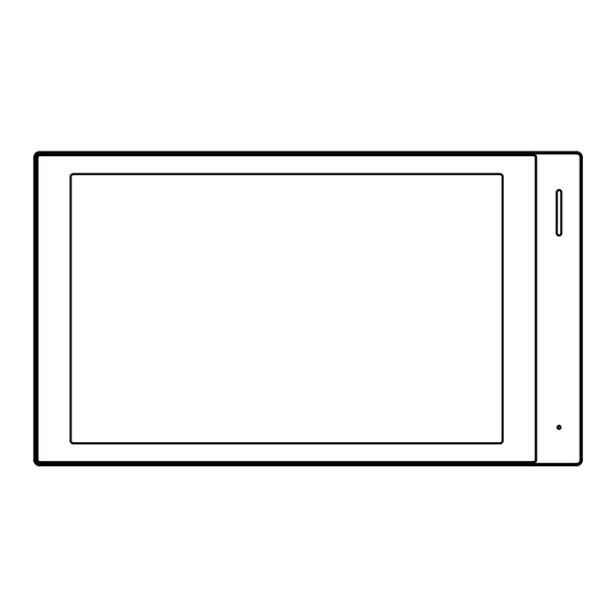
- Page 5 PICTURES MODEL: H616 Speaker 8'' Capacitive Touch Screen Microphone TF Card Slot...
- Page 6 SYSTEM CONFIGURATION Apartment Alarm Sensors Alarm Sensors H616 H616 9000+ Max 9000+ Max DNAKE DNAKE Smart Life APP Smart Life APP IP Camera Lock PoE Switch Master Station Door Station 9 Max RVV2*0.5 CAT-5e Internet...
- Page 7 SYSTEM DIAGRAM 1. Network/PoE Connect with door station, indoor monitor or other network equipment by network switch. When indoor monitor has PoE function, the interface can supply power by connecting with PoE network switch. 2. Power The power interface of Indoor Monitor connects to 12V DC power. 12V DC Power Power...
- Page 8 3. Relay Connect to the lock module(independent power supply is necessary for the lock). The maximum input of relay terminal is 30VDC/1A, and it is not allowed to exceed this limit value in use. Normally open port of the relay Common port of the relay Normally closed port of the relay Relay Output...
- Page 9 5. Siren/Alarm Interface of alarm zones connects with normally-open or normally-closed switch. When the alarm zone is triggered, it will output 12V/100mA power.
- Page 10 INSTALLATION MODEL: H616 (Surface Mounting-86 Mounting Box) Screws Mounting Box Screws Bracket Product size: 217x124x14mm...
- Page 11 MODEL: H616 (Surface Mounting-118 Mounting Box) Mounting Box Screws Screws Bracket Product size: 217x124x14mm...
- Page 12 MODEL: H616 (Surface Mounting-Round Mounting Box) Screws Mounting Box Screws Bracket Product size: 217x124x14mm...
- Page 13 SAFETY INSTRUCTIONS In order to protect you and others from harm or your device from damage, please read the following information before using the device. Do not install the device in the following places: Do not install the device in high-temperature and moist environment or ●...
- Page 14 FCC WARNING This device complies with Part 15 of the FCC Rules. Operation is subject to the following two conditions: (1) This device may not cause harmful interference, and (2) this device must accept any interference received, including interference that may cause undesired operation.
- Page 16 V1.1 600110186101...
Need help?
Do you have a question about the H616 and is the answer not in the manual?
Questions and answers