Furuno CSH-10 Operator's Manual
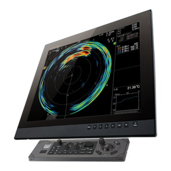
Scanning sonar
Hide thumbs
Also See for CSH-10:
- Installation manual (133 pages) ,
- Installation manual (98 pages) ,
- User manual (13 pages)
Table of Contents
Advertisement
Quick Links
Advertisement
Table of Contents

Related Manuals for Furuno CSH-10


Summary of Contents for Furuno CSH-10
- Page 1 OPERATOR'S MANUAL SCANNING SONAR CSH-10 Model www.furuno.com...
- Page 2 ・FURUNO Authorized Distributor/Dealer 9-52 Ashihara-cho, Nishinomiya, 662-8580, JAPAN A : JUN 2024 Printed in Japan All rights reserved. A1 : OCT . 03, 2024 Pub. No. OME-13780-A1 (TAYA ) CSH-10 0 0 0 2 0 0 8 2 9 1 1...
-
Page 3: Important Notices
How to discard a used battery Some FURUNO products have a battery(ies). To see if your product has a battery, see the chapter on Maintenance. If a battery is used, tape the + and - terminals of the battery before disposal to pre- vent fire, heat generation caused by short circuit. -
Page 4: Safety Instructions
Continued use of the equipment can cause Fire or electrical shock can result if a liquid fire or electrical shock. Contact a FURUNO spills into the equipment. agent for service. Handle the transducer carefully. - Page 5 A warning label is attached to the processor unit, the transceiver unit and the hull unit of the system. Do not remove any label. If a label is missing or damaged, contact a FURUNO agent or dealer about replacement. WARNING WARNING Moving main shaft can pinch and cut.
-
Page 6: Table Of Contents
TABLE OF CONTENTS FOREWORD .........................viii SYSTEM CONFIGURATION ..................xiii OPERATIONAL OVERVIEW .................1-1 1.1 Controls Overview...................... 1-1 1.1.1 Control unit SCU-002 ..................1-1 1.1.2 Remote controller FSV-854-MK2 (Option) ............. 1-3 1.1.3 Remote controller SCU-001 (Option) ............. 1-3 1.1.4 Small switch box SCU-003 (Option)............... 1-4 1.2 Basic Menu Operation.................... - Page 7 TABLE OF CONTENTS 3.2.3 How to adjust the audio volume ..............3-4 3.3 The Fish Alarm ......................3-5 3.3.1 How to activate/deactivate the fish alarm ............3-5 3.3.2 How to set alarm level ..................3-6 3.4 How to Measure the Speed of School of Fish ............3-6 3.4.1 How to enter a fish mark ................3-6 3.4.2...
- Page 8 TABLE OF CONTENTS DATA RECORD/PLAY...................7-1 7.1 How to Specify Where to Save Still and Motion Images ..........7-1 7.2 How to Save a Still Image ..................7-2 7.3 How to Show the Saved Still Image ................7-3 7.4 How to Save Motion Images ..................7-5 7.5 How to Play Back Motion Images ................
-
Page 9: Foreword
Thank you for considering and purchasing FURUNO equipment. Features The FURUNO CSH-10 Color Scanning Sonar is a full-circle electronic scanning sonar. The CSH- 10 consists of a control unit, processor unit, transceiver unit, hull unit and monitor (supplied locally), and detects and instantaneously displays schools of fish and underwater conditions. - Page 10 FOREWORD Standards used in this manual • Key names are shown in boldface type. • Menu items and on-screen indications are shown in brackets. • Messages shown on the display are enclosed in quotations. • The colors mentioned in this manual are the default colors. Your colors may be different. •...
- Page 11 FOREWORD Altera-SoCFPGA-HardwareLib-MPL Altera MPL preloader, configured for use with SDMMC/Connectal. (The initial commit is the un- modified sourcecode from Altera) The original source was extracted from: altera/14.1/embedded/examples/software/Altera-SoCFP- GA-HardwareLib-MPL.tar.gz and has BSD copyright with the additional restriction: "This software may only be used to run on Altera products, or to program Altera devices." All subsequent edits by Cambridgehackers are under the same copyright.
- Page 12 FOREWORD This product includes cryptographic software written by Eric Young (eay@cryptsoft.com). This product includes software written by Tim Hudson (tjh@cryptsoft.com). Original SSLeay License Copyright (C) 1995-1998 Eric Young (eay@cryptsoft.com) All rights reserved. This package is an SSL implementation written by Eric Young (eay@cryptsoft.com). The imple- mentation was written so as to conform with Netscapes SSL.
- Page 13 FOREWORD CE/UKCA declaration With regards to CE/UKCA declarations, please refer to our website (www.furuno.com), for further information about RoHS conformity declarations. Disclosure of Information about China RoHS With regards to China RoHS information for our products, please refer to our website...
-
Page 14: System Configuration
SYSTEM CONFIGURATION Remote Controller FSV-854-MK2 External External monitor monitor Echo Sounder Control Unit SCU-002 AD Converter Gyrocompass AD-100 Processor Unit NMEA0183 devices (max. five units) CSH-1003 External KP EXT KP External KP INT KP Speaker SEM-21Q USB 3.0 devices (max. two units) USB 2.0 devices (max. -
Page 15: Operational Overview
OPERATIONAL OVERVIEW Controls Overview 1.1.1 Control unit SCU-002 TARGET DELETE CENTER LOCK MARK USER PROG TILT GAIN RANGE EVENT FISH EVENT FISH Proximity sensor Key/Control Description Turns on/off the power of the system. Completely retracts the transducer. Not used. Completely lowers the transducer. USER PROG Selects user-programmed settings (P1 to P10). -
Page 16: Proximity Sensor
1. OPERATIONAL OVERVIEW Key/Control Description Wheel knob • Turn: Selects the menu item. • Turn: Adjusts the setting values. • Turn: Adjusts the gain, range, tilt angle, or sets user-programmed settings. • Short press: Confirms the selection. • Long press: Opens the [Select Mark] window. MENU/ESC •... -
Page 17: Remote Controller Fsv-854-Mk2 (Option)
1. OPERATIONAL OVERVIEW 1.1.2 Remote controller FSV-854-MK2 (Option) The optional remote controller (connected to the processor unit) allows you to remote- ly operate the following functions. Note 1: Do not leave the remote controller where it can be exposed to water or water splashes. -
Page 18: Small Switch Box Scu-003 (Option)
1. OPERATIONAL OVERVIEW Function (default settings) • Short press: Confirms the operating status of the unit. • Long press: Turns on/off the power of the unit. Performs the function assigned to the function key F1. Performs the function assigned to the function key F2. -
Page 19: Basic Menu Operation
1. OPERATIONAL OVERVIEW Basic Menu Operation The CSH-10 has the following four menu options: User programmed-settings, sonar, sounder, and system. You can operate the menus by using the wheel knob or the trackball. 1. Press the MENU/ESC key to open the menu. - Page 20 1. OPERATIONAL OVERVIEW 6. Rotate the wheel knob or the trackball and select the menu item to adjust. The currently selected menu item turns light blue, and the menu item and its set- tings are enclosed with by a light-blue frame. Currently selected menu item (light blue) Light blue frame...
- Page 21 1. OPERATIONAL OVERVIEW Drop down list Current selection is shown in green. 1) Rotate the wheel knob or trackball to select the desired choice. The currently selected choice turns light-blue and is enclosed with a light-blue frame. Currently selected option (green) Currently selected option (light-blue frame) 2) Press the wheel knob or left key to confirm.
-
Page 22: Basic Operating Procedure
How to enter characters When you select an item that requires text input, the software keyboard appears as shown below. The CSH-10 allows you to enter English alphabet (uppercase and low- ercase characters), numbers, Japanese katakana, and symbols. [Shift] Change the characters and symbols. -
Page 23: How To Lower The Transducer
1. OPERATIONAL OVERVIEW 1.3.2 How to lower the transducer To lower the transducer, reduce the ship speed to less than 18 kn, and press the key. The lamp to the right of the key flashes while lowering the transducer, and the message "Lowering "... -
Page 24: How To Start Transmission
1. OPERATIONAL OVERVIEW 1.3.3 How to start transmission [Transmission] is set to [OFF] in the default condition. To start transmission, do the following operations. If it is set to [ON], transmission automatically starts as the trans- ducer is lowered after turning on the power again. Transmission automatically stops when the transducer is completely retracted. -
Page 25: How To Select The Display Mode
1. OPERATIONAL OVERVIEW 1.3.5 How to select the display mode There are two types of display mode available on this equipment. The mode can be switched on the [Sonar] menu. Display Description Display mode The 360° sonar echo image of own ship is displayed on the echo picture display area of the horizontal single... - Page 26 1. OPERATIONAL OVERVIEW 1. Open the menu. 2. Select the [Sonar] tab from the main menu. 3. Select the [Sonar] tab from the sub menu. 4. Select [Display Mode]. 5. Select one of the display modes. 6. Close the menu. Sonar display example Net shoot data Fish mark *¹...
-
Page 27: Presentation Mode
Water temperature Depth Depth and depth can be indicated on the track. or water temperature or water temperature Consult with a FURUNO technician for how to display the data. 1-13... -
Page 28: How To Select The Detecting Range
Note 3: By default, the range is automatically changed when target lock is active, and cannot be changed by the operator. To enable range adjustment in target lock, consult with a FURUNO dealer. 1.3.7 How to adjust the gain The GAIN control adjusts receiver sensitivity. -
Page 29: How To Raise The Transducer, Turn Off The Power
1. OPERATIONAL OVERVIEW Note: The gain can also be adjusted directly from the gain indica- tion. Place the cursor over the gain indication to highlight it in light ° blue, and then turn the wheel knob to confirm the gain. 1.3.8 How to raise the transducer, turn off the power 1. -
Page 30: Tilt Angle
1. OPERATIONAL OVERVIEW Tilt Angle The tilt angle shows the angle from the sea surface at which the sound wave is emit- ted. When the sound wave is emitted horizontally, it is said to be zero (0) degrees, and when emitted vertically, 90 degrees. 1.4.1 How to set the tilt angle To manually set the tilt angle, operate the TILT lever. - Page 31 1. OPERATIONAL OVERVIEW 3) Select [Auto Tilt Lower End]. 4) Set the lower angle from -5° to 60°. 7. Adjust the automatic tilt settings if necessary as follows. 1) Select [Auto Tilt Angle]. 2) See the following table and set the auto tilt angle from 1° to 5°. 3) Select [Auto Tilt TX Count].
-
Page 32: How To Distinguish Fish Echoes From The Bottom
1. OPERATIONAL OVERVIEW 1.4.3 How to distinguish fish echoes from the bottom Finding the proper tilt angle is of utmost importance when searching for fish, especially in coastal water fishing, where the depth of the fishing ground is from 50 to 100 m. In this type of fishing ground, it is imperative that the bottom echo be always displayed to properly distinguish between fish and the bottom. -
Page 33: Tilt Angle For Surface Fish
1. OPERATIONAL OVERVIEW 1.4.4 Tilt angle for surface fish An ultrasonic wave emitted from the sonar transducer forms an oval-shaped beam with a width of approximately 6° in the vertical direction (vertical beam width at -3 dB). The tilt angle indicates the angle between the centerline of the beam and the horizon- tal plane. -
Page 34: Range And Bearing To A Target
1. OPERATIONAL OVERVIEW Range and Bearing to a Target Operate the trackball to place the cross-hair cursor (trackball mark) on the target you want to measure the range and bearing. The range from the own ship position, bear- ing, and depth to the target appear at the upper left corner of the sonar display. The latitude and longitude of the cross-hair cursor position are also displayed on the bot- tom of the display. -
Page 35: Fine Tuning The Sonar Picture
FINE TUNING THE SONAR PIC- TURE How to Eliminate Unwanted Echoes Echoes from targets such as the bottom and fish return to the transducer in order of the distance to them, and when we compare their intensities at the transducer face, those from nearer targets are generally stronger when their reflecting properties are nearly equal. -
Page 36: How To Suppress Bottom Tail
2. FINE TUNING THE SONAR PICTURE How to Suppress Bottom Tail As noted earlier, schools of fish (echoes) located near the bottom are sometimes dif- ficult to detect because you have to discriminate them from the bottom reflections. With [AGC Near], [AGC Far], or [TX Pulse Length] (in the [User Prg] menu) used prop- erly, the tail of bottom reflections is decreased, making it easier to discriminate bottom fish. -
Page 37: How To Suppress Bottom Echoes And Sea Clutters In Shallow Fishing Grounds
2. FINE TUNING THE SONAR PICTURE 2. Select the [User Prg] tab from the main menu. 3. Select one of the following settings. • [Noise Suppression]: Suppresses noise from weak echoes such as sea clutter, plankton, and distant sea bottom. •... -
Page 38: How To Reject Sonar Interference And Noise
2. FINE TUNING THE SONAR PICTURE How to Reject Sonar Interference and Noise While observing the sonar picture, you may encounter occasional (or periodical) noise and interference. These are mostly caused by on-board electronic equipment, engine, propeller noise, or electrical noise from other sonars being operated on other ships nearby. -
Page 39: How To Reject Interference With Transmission Interval
2. FINE TUNING THE SONAR PICTURE 2. Select the [User Prg] tab from the main menu. 3. Select [Noise Limiter]. 4. Adjust the setting value (setting range: 0 to 10). The higher the setting, the greater the noise limiter effect. 5. -
Page 40: How To Choose Beamwidth
2. FINE TUNING THE SONAR PICTURE 2.4.6 How to use echo average The echo average function adjusts echo afterglow - the amount of time an echo signal remains on the display. This feature can be useful for watching echo movement. Ad- just the setting so that targets are clearly visible on the display. -
Page 41: Advanced Sonar Operation
ADVANCED SONAR OPERATION How to Track a School of Fish (Target Lock) The target lock function automatically tracks a school of fish so you will not lose sight of it on the display. Two types of target lock modes are available: position tracking (Target Mark) and tracking of school of fish (Fish). -
Page 42: Target Mark Mode
3. ADVANCED SONAR OPERATION Note: If the vector or track is not shown on the display, contact your dealer. If the target is lost, the target lock mark color changes from white to red, and the tracking mode changes to position mode (Target Mark) at that position. When the sonar detects and tracks the target again, the tracking mode (Fish) is restored. -
Page 43: How To Turn The Audio On/Off
3. ADVANCED SONAR OPERATION 3.2.1 How to turn the audio on/off To enable the audio function, input from external devices is required (see page AP-7). 1. Open the menu. 2. Select the [Sonar] tab from the main menu. 3. Select the [Sonar] tab from the sub menu. -
Page 44: How To Adjust The Audio Volume
3. ADVANCED SONAR OPERATION dible alarm sounds from the speaker. When this function is turned off, the audio bearing marker changes to the bearing marker. Audio bearing marker Bearing marker : The audio bearing marker tracks the target while the target lock is R 400m activated. -
Page 45: The Fish Alarm
3. ADVANCED SONAR OPERATION The Fish Alarm The fish alarm generates an audio alarm when a fish echo above a certain strength enters the set alarm zone. 3.3.1 How to activate/deactivate the fish alarm To set the fish alarm, do as follows. 1. -
Page 46: How To Set Alarm Level
3. ADVANCED SONAR OPERATION 3.3.2 How to set alarm level The alarm level sets the minimum echo strength at which the fish alarm is activated. The echo strength is equivalent to echo color. 1. Open the menu. 2. Select the [Sonar] tab from the main menu. 3. - Page 47 3. ADVANCED SONAR OPERATION Note 1: The time and distance between pressings of the FISH key should be as long as possible to increase accuracy of measurement. For more accurate measurement, repeat the procedure two or three times. Note 2: In the default arrangement, fish mark 1 can be entered on the echo display area by clicking on the display.
-
Page 48: How To Delete Fish Marks
3. ADVANCED SONAR OPERATION 3.4.2 How to delete fish marks You can delete fish marks individually or collectively. See page 9-6. Erase with the DELETE MARK key 1. Place the cross-hair cursor on the fish mark to delete. The fish mark color chang- es to red when the fish mark is correctly selected. -
Page 49: Event Mark
3. ADVANCED SONAR OPERATION Event Mark The event mark is useful for finding the horizontal range, depth, and bearing to a lo- cation from the current position. There are two types of event marks: event mark 1 ) and event mark 2 ( ). -
Page 50: How To Delete An Event Mark
3. ADVANCED SONAR OPERATION 3.6.2 How to delete an event mark You can delete event marks individually or collectively by the following procedures. See page 9-6. With the DELETE MARK key 1. Place the cross-hair cursor on the event mark you want to delete. The color of the mark changes to red. - Page 51 3. ADVANCED SONAR OPERATION 8) From the drop-down list, select the function key from F1 to F4 to assign the [Estimate Mark 2] function. 9) Click []. 10) Close the menu. 2. Press the function key to which the [Estimate Mark 1] function is assigned. The estimate mark 1 appears.
-
Page 52: Using The [Select Mark] Window
3. ADVANCED SONAR OPERATION 3.7.2 Using the [Select Mark] window 1. Long-press the wheel knob to show the [Select Mark] window. Estimated mark 1 & 2 2. Select [1] (estimate mark 1). 3. Click on the screen to show the estimate mark 1. 4. -
Page 53: Select Mark Window
3. ADVANCED SONAR OPERATION Select Mark Window [Event Mark 1], [Event Mark 2], [Fish Mark 1], [Fish Mark 2], [Target Lock], [Estimate Mark 1], and [Estimate Mark 2] can be entered from the [Select Mark] window. 1. Long-press the wheel knob to show the [Select Mark] window. Name of selected mark 2. -
Page 54: Net Data
3. ADVANCED SONAR OPERATION 3.10 Net Data Using the net shoot mark, you can observe net data after shooting the net. This func- tion requires appropriate data input (see page AP-7). 3.10.1 How to set the net shooting history After the net shoot mark is entered, the net shooting history mark appears at the own ship Net shooting history mark position with the interval between marks set in... - Page 55 3. ADVANCED SONAR OPERATION move plot marks are displayed. The net move plot marks show how the net is be- ing swept by the current. Net shooting data Bearing from the net shooting start point 0.53 NM 5:32 Time elapsed from the net shooting Net shoot mark Net shooting history mark Current vector...
- Page 56 3. ADVANCED SONAR OPERATION This page is intentionally left blank. 3-16...
-
Page 57: Fish Finder Mode
FISH FINDER MODE This equipment can show the picture from the fish finder in combination with the sonar echoes. Note: Connection to a fish finder is required to use the fish finder dual display mode. Fish Finder Display Overview The figure below shows the items that appear on the fish finder display. Distance from the own ship position to the cross cursor position... -
Page 58: How To Adjust The Gain
4. FISH FINDER MODE 1. Open the menu. 2. Select the [Sounder] tab from the main menu. 3. To set the range, select [Range]. 4. Set the range (setting range: 5 m to 1000 m). 5. To set the shift, select [Shift]. 6. -
Page 59: How To Select Picture Advance Speed
4. FISH FINDER MODE How to Select Picture Advance Speed The picture advance speed determines how quickly the vertical scan lines run across the screen. When selecting a picture advance speed, keep in mind that a fast advance speed expands a school of fish horizontally while a slow advance speed contracts it. Note: Use the same settings as the connected fish finder. -
Page 60: How To Suppress Interference
4. FISH FINDER MODE How to Suppress Interference Interference from other sonars being operated on other ships nearby, or induction noise from electronic equipment on your ship may appear on the display. These types of interference can reduced with the interference rejector. Interference from Electrical interference other fish finders... -
Page 61: How To Erase Weak Echoes
4. FISH FINDER MODE 6. Select one of the following color settings. • [Standard]: Strong color echoes are displayed as they are, and weak echoes are shown smaller, when the clutter level is increased. • [Liner]: All echoes are displayed smaller, when the clutter level is increased. 7. -
Page 62: Smoothing
4. FISH FINDER MODE Unwanted echoes suppressed. Unwanted echoes appear. 100 m 100 m TVG OFF: TVG adjusted: Schools of fish of equal strengths Schools of fish of equal strengths shown in different sizes and colors. shown in same sizes and colors. 1. -
Page 63: How To Remove Unwanted Echoes Near The Surface
4. FISH FINDER MODE 4.11 How to Remove Unwanted Echoes Near the Sur- face The STC feature can remove unwanted echoes (air bubbles, planktons, etc.) near the surface. Use this function when you want to see fish near the surface clearly. 1. - Page 64 4. FISH FINDER MODE This page is intentionally left blank.
-
Page 65: Numeric And Graphic Data Display Area
NUMERIC AND GRAPHIC DATA DISPLAY AREA Numeric and Graphic Data Display The following numeric/graphic data are shown on the right side of the horizontal single display. Heading * Ship Course * Navigation data Ship Speed * LAT/LON [GPS] * ’ Ship’s position ’... -
Page 66: Numeric/Graphic Data Description
5. NUMERIC AND GRAPHIC DATA DISPLAY AREA Numeric/Graphic Data Description When data is lost, the last value is shown in red. Information displayed on the screen can be changed to on or off from the system menu. For details about the system menu, contact your dealer. - Page 67 5. NUMERIC AND GRAPHIC DATA DISPLAY AREA Numeric & Available Description Display range Graphic formats item Fish est Estimated index value of 0 to 9999 Indx fish school, calculated from the echo for Fish Mark 1&2. Water temperature Water Shows water temperature -10.00°C to 40.00°C °C, °F TEMP...
- Page 68 5. NUMERIC AND GRAPHIC DATA DISPLAY AREA This page is intentionally left blank.
-
Page 69: How To Customize The Sonar
HOW TO CUSTOMIZE THE SO- This chapter describes how to use the function keys, user program control, remote controller FSV-854-MK2 (option), and remote controller SCU-001 (option). Also, res- toration of scan settings is described. Function Keys Often-used menu items can be assigned to the function keys to enable quick access to those items. -
Page 70: How To Assign Menu Items To The Function Keys
6. HOW TO CUSTOMIZE THE SONAR 6.1.2 How to assign menu items to the function keys To assign other menu items to the function keys (or software function keys), do as fol- lows. Note 1: Some menu items cannot be assigned to the function keys. See the menu tree on page AP-1 for details. -
Page 71: User Programs
6. HOW TO CUSTOMIZE THE SONAR 1) To continue, select [Replaced]. The following message appears. 2) Select the function key to be replaced, using the software function key. The following message appears for five seconds to show that the menu item is suc- cessfully replaced to the function key. -
Page 72: How To Select A User Program
6. HOW TO CUSTOMIZE THE SONAR 6.2.1 How to select a user program Rotate the USER PROG control clockwise or counterclockwise to select the program number from P1 to P10. The program number selected appears at the top right corner of the screen, to the right of "P". -
Page 73: How To Restore Scan Settings (Range, Tilt Angle, Gain)
6. HOW TO CUSTOMIZE THE SONAR 5. Select [Yes]. Text box 6. From the drop-down list, select a number from [P1] to [P10]. A maximum of ten presets can be registered. 7. Do the operations below to enter the user program title. The title entry column is located under the preset number. -
Page 74: How To Restore The Settings For Scanning
6. HOW TO CUSTOMIZE THE SONAR 3. Select the [Sonar] tab from the sub menu. 4. To change range, select [Reset Range 1] or [Reset Range 2]. 5. Select one of the following options. • [OFF]: To keep the current range af- ter restoring the settings. -
Page 75: Remote Controller Fsv-854-Mk2 (Option)
6. HOW TO CUSTOMIZE THE SONAR Remote Controller FSV-854-MK2 (Option) The keys on the remote controller can be reprogrammed with the functions of your choice. 1. Open the menu. 2. Select the [System] tab from the main menu. 3. Select the [InitSetting] from the sub menu. Note: The settings for Ch7 to Ch10 are available only when an external switch is connected to the processor unit (TB1). -
Page 76: How To Set Up Bluetooth ® Pairing
6. HOW TO CUSTOMIZE THE SONAR ® 6.5.1 How to set up Bluetooth pairing Transmission between the processor unit and remote controller is done using Blue- ® tooth . However, to use a remote controller, you need to pair the processor unit with the remote controller. - Page 77 6. HOW TO CUSTOMIZE THE SONAR 9. Select the remote controller to be paired, and click [OK]. Remote control connection Select the remote control number to register, then press [OK]. remote control No.1 (Registered) remote control No.2 remote control No.3 (Registered)) remote control No.4 Cancel 10. Select the remote controller from No.1 to No.4, then click [OK]. Remote control connection Press [OK] to restart. 11.
-
Page 78: How To Cancel Pairing
6. HOW TO CUSTOMIZE THE SONAR 6.5.2 How to cancel pairing To undo pairing, do as follows. 1. Open the menu. 2. Select the [System] tab from the main menu. 3. Select the [InitSetting] from the sub menu. 4. Select [Disconnect remote control]. 5. -
Page 79: How To Check Currently Assigned Functions
6. HOW TO CUSTOMIZE THE SONAR horizontally, for safety reasons. For example, if you assign [Retract] to the B key, assign [Full Protrude] to the D or E key. TILT TILT RANGE RANGE GAIN GAIN Side-by-side keys Keys in separate rows Not recommended Recommended When [Retract] or [Full-Protrude] is selected, the following message appears. - Page 80 6. HOW TO CUSTOMIZE THE SONAR This page is intentionally left blank. 6-12...
-
Page 81: Data Record/Play
DATA RECORD/PLAY How to Specify Where to Save Still and Motion Images Select the location where to save still images and video files. 1. Open the menu. 2. Select the [System] tab from the main menu. 3. Select the [Record] tab from the sub menu. 4. -
Page 82: How To Save A Still Image
7. DATA RECORD/PLAY 6. Select the storage location from the destination list. Note 1: To set an external storage device (USB device) as the destination, click [ ] on the right end of the destination list and change the destination from the [Local Disc (D:)]. -
Page 83: How To Show The Saved Still Image
7. DATA RECORD/PLAY 8. After entering the comment, click [Enter]. The software keyboard and the preview image disappear from the display. 9. To finish, select [Quit] at the top of the window. Saving from [Record Still Images] 1. Open the menu. 2. - Page 84 7. DATA RECORD/PLAY 4. Select [Play Still Images]. The latest still image is shown on the display. The window can be resized or moved by drag and drop. Also, you can zoom in or out using the wheel knob, and resize the window by drag and drop within the win- dow if the still image is not fully displayed.
-
Page 85: How To Save Motion Images
7. DATA RECORD/PLAY How to Save Motion Images The image shown on the display can be saved as a motion image. Note: When saving motion images, it is recommended to save the images to an ex- ternal hard drive, connected to the USB port on the processor unit. 1. -
Page 86: How To Play Back Motion Images
7. DATA RECORD/PLAY How to Play Back Motion Images You can play back motion images as follows: 1. Open the menu. 2. Select the [System] tab from the main menu. 3. Select the [Record] tab from the sub menu. 4. Select [Motion Image]. File name list 5. -
Page 87: How To Delete Files
7. DATA RECORD/PLAY How to Delete Files You can delete unnecessary files (still images, motion images, setting data, etc.) as indicated below. 1. Open the menu. 2. Select the [System] tab from the main menu. 3. Select the [Record] tab from the sub menu. 4. - Page 88 7. DATA RECORD/PLAY This page is intentionally left blank.
-
Page 89: How To Interepret The Display
HOW TO INTEREPRET THE DIS- PLAY Bottom Echo When the tilt angle is changed, the bottom echo appears on the screen. When the tilt angle is decreased, the bottom trace becomes wider and weaker. By observing the bottom condition on the screen, the skipper can prevent the net from being damaged by a reef of a shipwreck. -
Page 90: School Of Fish
8. HOW TO INTEREPRET THE DISPLAY School of Fish A school of fish appears as a mass of echoes. The color of the mass shows the den- sity. To know the distribution and center point of a school of fish, choose several dif- ferent tilt angles. -
Page 91: Sea Surface Reflections
8. HOW TO INTEREPRET THE DISPLAY Sea Surface Reflections To reduce sea surface reflections, set the tilt angle to 4° or more, so that the upper edge of the sonar beam does not hit sea surface, or adjust the near gain. When the sonar is used with a narrow tilt angle, the sea surface reflections cover a large area as illustrated below. -
Page 92: False Echo By Sidelobe
8. HOW TO INTEREPRET THE DISPLAY False Echo by Sidelobe An ultrasonic wave is emitted only in the direction set by the TILT lever. However, in practice, there are some emissions outside the main beam, called sidelobes. Energy of the sidelobe is fairly weak, but when the sonar is used in comparatively shallow wa- ter with a hard and rocky bottom, strong target signals may be detected by the sidelo- be. -
Page 93: Other Settings
OTHER SETTINGS This chapter describes setting details for each menu. [USER PROG] Menu The [USER PROG] menu provides the settings related to the sonar image. Menu item Description TX Interval Sets the transmission interval (see subsection 2.4.4). TX Pulse Length Sets the transmission pulse length (see subsection 2.2.2). - Page 94 9. OTHER SETTINGS Menu item Description Color Setting Changes the echo colors from the Color Setting window. See below "How to change color setting". Color Curve Setting Changes the echo color curve setting from the Color Curve Setting. See "How to change the color curve setting"...
- Page 95 9. OTHER SETTINGS 3. Select the color on the [Changed] pallete you want to change. The color change is applied to the color pallete indicated by an arrow (►). 4. Set the display color from one of the following methods. Select from the 32-color pallete Select the color from the [Current] pallete, then the color selected is applied to where indicated with an arrow ().
- Page 96 9. OTHER SETTINGS How to change the color curve setting The ten different color curves can be set to each user program number from P1 to P10. Do as follows to set a color curve. 1. Select [Color Curve Setting] to show the [Color curve setting] window. Default model Current status 2.
-
Page 97: Sonar] Menu
9. OTHER SETTINGS [Sonar] Menu 9.2.1 [Sonar] menu The [Sonar] menu provides the settings related to display and functions in the horizon- tal single display mode. Menu item Description Display Mode Selects the display mode (see subsection 1.3.5). Auto Tilt Turns auto tilt ON or OFF (see subsection 1.4.2). -
Page 98: Mark] Menu
9. OTHER SETTINGS Menu item Description Audio Turns the audio ON or OFF (see subsection 3.2.1). Audio Gain Adjusts the audio volume (subsection 3.2.3). Ship Speed Alarm Sounds the buzzer when the ship exceeds the predetermined speed under the following conditions. This function is [ON] in the default setting. -
Page 99: Sounder] Menu
9. OTHER SETTINGS Menu item Description Delete ship’s track Deletes approx. 10% of the oldest ship’s track. Fish Estimate Mark Assigns fish estimate mark 1 and 2 functions to a function key 1 (F reg) (subsection 3.7.1). Fish Estimate Mark 2 (F reg) Net shoot mark (F Assigns net shoot mark function to a function key (see... -
Page 100: System] Menu
9. OTHER SETTINGS [System] Menu 9.4.1 [Record] menu The [Record] menu provides the settings related to still and motion images. See chapter 7 for details of each menu. 9.4.2 [Test] menu With the [Test] menu, you can perform diagnostic tests to confirm that the equipment is working properly. -
Page 101: Initsetting] Menu
9. OTHER SETTINGS 9.4.3 [InitSetting] menu The [InitSetting] menu provides the settings related to the remote controller (option), distance unit, and sound volumes. Menu item Description [Option List] Displays a list of option functions. Navnet Valid Invalid (grayout) [Remote Key Set- Assigns a function to each key of the remote controller FSV-854- ting 1 (Ch1)] to [Re- MK2 (see section 6.4). - Page 102 9. OTHER SETTINGS Menu item Description [Set remote control Assigns a function to the function key of the remote controller key (A)] to [Set re- SCU-001 (see subsection 6.5.3). mote control (E)] [Registered remote Confirms the functions assigned to the function keys of the re- control list] mote controller SCU-001 (see subsection 6.5.4).
-
Page 103: 10. Maintenance
10. MAINTENANCE This chapter provides maintenance and troubleshooting procedures for the operator. NOTICE WARNING ELECTRICAL SHOCK HAZARD Do not apply paint, anti-corrosive Do not open the equipment. sealant or contact spray to plastic parts or equipment coating. This equipment uses high voltage that can cause Those items contain products that can electrical shock. -
Page 104: Hull Unit Maintenance
10. MAINTENANCE 10.2 Hull Unit Maintenance Carry out the hull unit maintenance shown in the below figure. Apply Molytone Grease No.2 for gears every six months. Check the disc damper for an oil leakage every six months. Coat the screw shaft with Daphne Molytone Grease No.2 every six months. -
Page 105: Greasing The Gears
10. MAINTENANCE 10.2.1 Greasing the gears How to grease the gears 1. Unfasten the four bolts and remove the gear cover. Gear cover 2. Apply the Molytone Grease No.2 to the motor gears and to the screw shaft gears. How to apply the grease to the bearing parts Once every six months, remove the plug on the flange and inject Daphne Grease MP No. -
Page 106: How To Replace The Gasket
10. MAINTENANCE 2. Apply Molitony Grease No.2 to the screw shaft. Screw shaft LSW cover For 400 mm stroke length 10.2.2 How to replace the gasket If water is leaking from the main shaft, replace the gasket. Two spare gaskets are pro- vided on the cover of the main shaft. - Page 107 10. MAINTENANCE 3. Take the spare gasket from the cover of the main shaft cover and set it to the main shaft. Clamp Spare gasket Seal support plate Main shaft Gasket Hex. head bolt Spring washer Washer 4. Use the washer, the spring washer, and the hex. head bolt to fasten the two seal support plates.
-
Page 108: How To Check The Disc Damper
• Oil is leaking extensively. • Only a small amount is leaking. Leakage of a small amount of oil is not abnormal. In general, no replacement is necessary. However, when the leakage is significant, ask your FURUNO dealer for disc damper replacement. 10-6... -
Page 109: How To Replace The Fuse
10. MAINTENANCE 10.3 How to Replace the Fuse WARNING Use the proper fuse. Use of a wrong fuse can cause fire or damage the equipment. The processor unit and transceiver unit carry fuses that protect the system from over- current and equipment fault. If the power cannot be applied, check the fuse on the pro- cessor unit first. - Page 110 10. MAINTENANCE Put a clean, soft cloth on a flat surface, and place the removed ring and the ball on it. Ball Ring 2. Remove all the dust, dirt and other moisture inside the case. 3. Use a clean swab or non-woven cloth, and wipe the laser sensor cover and the supports.
-
Page 111: Troubleshooting
10. MAINTENANCE 10.6 Troubleshooting The table below provides common symptoms of equipment troubles, and the means to rectify them. If the problem cannot be solved with the information supplied in this manual, contact your dealer for service. Note: For the troubleshooting related to the remote controller SCU-001, see the user guide (C12-02301) shipped with the remote controller SCU-001. -
Page 112: Alarm And Warning
10. MAINTENANCE 10.7 Alarm and Warning When an alarm/warning condition occurs, Icon the system releases an audible alert : Warning icon (buzzer), and the alarm window appears : Alarm icon (flashing). The alarm (or warning) icon ap- pears in the window with a message and Warning/alarm message basic information. - Page 113 10. MAINTENANCE Message Level Meaning, Remedy Behavior Processor unit << SHIP SPD Alarm Meaning: Ship’s speed exceeded the pre- The alarm window ALARM!! >> determined speed (see page 9-6) when disappears. the transducer is protruded. Remedy: Right-click to silence the buzzer. Reduce the ship’s speed, and retract the transducer.
-
Page 114: Error Codes
10. MAINTENANCE 10.8 Error Codes When an error occurs inside the equipment, the error window shown below is shown at the bottom of the display.The equipment displays an icon along with (flashing) three-digit error code in yellow color. In case of multiple errors, error codes appear in numerical order, up to five error codes. -
Page 115: 2Operation Test
10. MAINTENANCE 3. Select the [Test] tab from the sub menu. : For technician use. Note: To find a noise source, turn transmission OFF under Test. Be sure to turn it ON again after the test. ([ON (No Change)] and [ON (No Alarm)] are for service techni- cians only.) 10.10.2 Operation test The operation test checks the operational status of each unit in the system. - Page 116 10. MAINTENANCE OPERATION TEST Processor Unit 105-XXXX-XX.XX Transceiver Unit TRCPU 105-XXXX-XX.XX 105-XXXX-XX.XX 105-XXXX-XX.XX 105-XXXX-XX.XX = OK = Enabled = OK S1 00000000(00) MAC Address = ******** = OK 0000(0) IP Address = ******** DATA = OK 0000(0) Subnet Mask = ******** 0000(0) MAC Address = ********...
- Page 117 10. MAINTENANCE Item Description Battery Displays the voltage of the backup battery. Control Unit: Displayed below two results only when two units are connected. 105-XXXX-XX.XX Displays the starter program number. 105-XXXX-XX.XX Displays the boot program number. 105-XXXX-XX.XX Displays the application program number. Displays the read-write test result of the memory ([OK] (white) or [NG] (red)).
-
Page 118: 3Board Test
10. MAINTENANCE 10.10.3 Board test The board test checks all the circuit boards in the system. To conduct this test, select [Board Test] from the [Test] menu. Press the MENU/ESC key to finish the test. BOARD TEST TRCPU 105-XXXX-XX.XX = OK = OK 105-XXXX-XX.XX = 21.5V... -
Page 119: 4Fan Monitor Test
10. MAINTENANCE Item Description Tacc Displays the measured temperature of the accelerator sensor. Tgyr Displays the measured temperature of the gyro sensor. Accel Displays the self-test result of the accelerator sensor. Gyro Displays the self-test result of the gyro sensor. TRX1 to 12 105-XXXX-XX.XX Displays the FPGA program number. -
Page 120: 5Panel Test / Sio Test
10. MAINTENANCE How to read the test results Item Description Transceiver Unit TRCPU FAN01 to 04 Displays the fan RPM (error judgment: less than 2856 rpm). Speed TRCPU FAN05 to 07 Displays "Reserve". Speed Processor Unit CPU BOARD_FAN1 Displays the fan RPM (error judgment: less than 2394 rpm). Speed 10.10.5 Panel test / SIO test The panel test or SIO test checks the operational status of the control unit’s keys,... -
Page 121: Panel Test
10. MAINTENANCE Panel test The panel test display layout corresponds to the key layout of the control unit. Do the following operations to check if the corresponding keys, buttons, knobs, etc. work properly. Item Check method Keys, left button, 1) Shows "1" while pressing keys other than the power key right button or the MENU/ESC key. - Page 122 10. MAINTENANCE Arrow cursor Remote controller Key Test B : 0 C : 0 PUSH JOYSTICK D : 0 E : 0 GAIN TILT RANGE GAIN TILT RANGE Remote controller Status Remote No.1 No.2 No.3 No.4 controller Connect Connected Not set Not set Not set Battery...
-
Page 123: 10.11 How To Retract The Transducer Manually
10. MAINTENANCE 10.11 How to Retract the Transducer Manually If the transducer cannot be raised automatically, carry out the following procedure and manually raise the transducer. CAUTION Turn the breaker off when raising the transducer manually. If raising or lowering the transducer while the breaker is turned on, the transducer motor automatically rises, which may cause injury. -
Page 124: 10.12 How To Check The Brake In The Hull Unit
10.12 How to Check the Brake In the Hull Unit The shafts of the hull unit are held in place by a motor brake. The motor brake should be checked once a year for proper operation. Contact your local FURUNO dealer for check. -
Page 125: Appx. 1 Menu Tree
APPX. 1 MENU TREE The factory values in the [User Prg] menu vary depending on the user program setting (P1-P10) (see section 6.2). In this menu tree, the factory values for the user program setting "P1" are shown. Menu/Esc User Prg User Prg TX Interval (Fixed (1 to 9;... - Page 126 APPX. 1 MENU TREE Mark Sounder Sounder Gain (0.0 to 10.0; 5.0) (F: No) Range (5 to 1000m; 200m) (F: No) Shift (0 to 1000m; 0m) (F: No) Clutter Level (0 to 100%; 40%) (F: No) Clutter Type (Standard, Liner) (F: No) Signal Level (0 to 9;...
- Page 127 APPX. 1 MENU TREE InitSetting Option List (F: No) Remote Key Setting (Ch1) (Tilt Up, Tilt Down, Range Up, Range Down, Gain Up, Gain Down, User Prog Up, User Prog Down, Retract, Full-Protrude, Event Mark1, Event Mark2, Fish Mark1, Fish Mark2, Estimate Mark1, Estimate Mark2, Net Shoot Mark, Erase Marks, Target Lock, Off Center, Range/Bearing, F1, F2, F3, F4, F5, F6, F7, F8, F9, F10) (F: No) Remote Key Setting (Ch2)(Same as Ch1;...
-
Page 128: Appx. 2 Error Code List
APPX. 2 ERROR CODE LIST The table below shows the error code, description, and meaning and remedy for the errors possi- bly occur in this equipment. Service technicians can check the detailed contents in [Error Code List ]of [System/Maintenance] menu. If the error is not still solved after conducting the remedy, contact your dealer. - Page 129 APPX. 2 ERROR CODE LIST Error Error Message Description Remedy Code SoC PLL Error Problem with the transceiv- • Conduct the board test er board(s). (see section 10.10.3) and RXBMF_FPGA PLL Er- check that the results for all items do not appear in red. FLT_FPGA PLL Error •...
- Page 130 APPX. 2 ERROR CODE LIST Error Error Message Description Remedy Code Backup Memory Error Backup memory write er- Restart the system. ror. Setting reset to its fac- tory default. Backup Data Error A backup data faultily set Restart the system. to default.
-
Page 131: Appx. 3 Data Input Requirements
APPX. 3 DATA INPUT REQUIRE- MENTS The following table outline the external data input requirements from the listed functions and/or displayed items. Function/Item See... Required data Bearing mark page 3-3 Heading data Own ship mark page 1-12 Heading data, Speed/Course data North mark page 3-1 Target Lock mark... -
Page 132: Appx. 4 Brake Test Sheet
APPX. 4 BRAKE TEST SHEET The motor brake should be checked once a year for any abnormalities. Please fill out the test re- sults to the check sheet below. AP-8... -
Page 133: Specifications
FURUNO CSH-10 SPECIFICATIONS OF SCANNING SONAR CSH-10 GENERAL Scanning method Full digital beam forming Frequency 83.5 kHz (selectable between 81.5 and 85.5 kHz) Power output 214 ± 2.0 dBPa Pulse length 0.5 to 20 ms Range Basic Range (m) Basic... - Page 134 FURUNO CSH-10 Audio output 1 port, 10 W, 4 ohms, monaural Gyrocompass 1 port, AD-10 Echo sounder input 1 port, VI-1100A (analog) Contact closure 1 port, for remote control or external switch 4 ports, USB2.0: 2 ports, USB3.0: 2 ports...
-
Page 135: Index
INDEX AGC ............2-2 Maintenance..........10-1 Alarm............. 10-10 Hull unit maintenance......10-2 Audio bearing ..........3-3 Trackball maintenance ......10-7 Audio function ........... 3-3 Mark menu ..........9-6 Audio volume ..........3-4 Menu operation ......... 1-5 Automatic tilt function ......1-16 Menu tree ..........AP-1 Motion ............ - Page 136 INDEX Software function keys ......1-20 Speaker volume ........9-10 Status messages ........10-12 STC ............4-7 System configuration ........xiii System menu ..........9-8 Target lock ..........3-1 Test menu ........9-8 10-12 Tilt indication ..........1-16 Trackball mark .........1-20 Trackball speed........9-10 Transmission pulse ........4-7 Troubleshooting ........10-9 TRX position indicator ........1-9 TVG............4-5 TX and RX ..........4-7...
Need help?
Do you have a question about the CSH-10 and is the answer not in the manual?
Questions and answers