EINHELL AGILLO 36/255 BL (34.113.20) Manual
- Original operating instructions (106 pages) ,
- Original operating instructions (264 pages) ,
- Operating instructions manual (55 pages)
Advertisement
- 1 Explanation of the warning signs on the equipment
- 2 Safety regulations
- 3 Layout and items supplied
- 4 Proper use
- 5 Technical data
-
6
Before starting the equipment
- 6.1 Fitting the guard hood
- 6.2 Fitting the additional handle
- 6.3 Fitting the long handle
- 6.4 Adjusting the angle of the additional handle
- 6.5 Removing/fitting the cutting line unit
- 6.6 Guard hood for use with the cutting blade
- 6.7 Guard hood for use with the cutting line
- 6.8 Fitting/removing the cutting blade
- 6.9 Using the harness
- 6.10 Installing the battery
- 6.11 Charging the battery
- 6.12 Battery capacity indicator
- 7 Operation
- 8 Cleaning, maintenance and ordering of spare parts
- 9 Storage and transport
- 10 Faults
- 11 Charger indicator
- 12 Service information
- 13 Documents / Resources
Explanation of the warning signs on the equipment

- Warning!
- Read the directions for use before operating the equipment!
- Wear protective headgear, goggles and ear muffs!
- Wear sturdy, non-slip footwear!
- Wear safety gloves!
- Protect the equipment from rain and damp!
- Be careful of objects being thrown out.
- All bystanders must be kept at least 15 m from the machine!
- The equipment continues to rotate!
- Beware of recoil!
- Do not use any saw blades.
Safety regulations
The corresponding safety information can be found in the enclosed booklet.

Read all safety regulations and instructions. Any errors made in following the safety regulations and instructions may result in an electric shock, fire and/or serious injury.
Keep all safety regulations and instructions in a safe place for future use.
Children are not allowed to use this equipment. Children should be supervised so that they do not play with the equipment. Children are not allowed to carry out cleaning or maintenance. This equipment is not allowed to be used by people with limited physical, sensory or mental capacities or by those with insuffi cient knowledge or experience unless they are supervised or instructed by a person who is responsible for them.
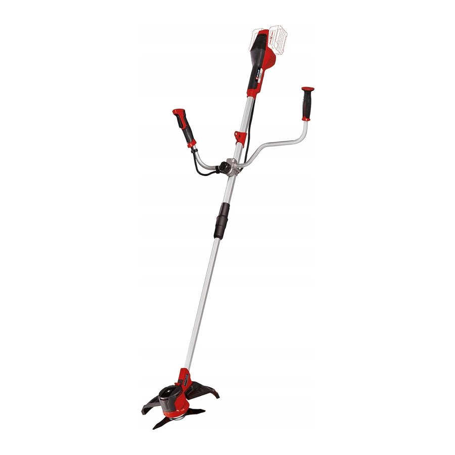
Layout and items supplied
Layout


- Battery
- On/Off switch
- Safety lock-off
- Strap attachment
- Additional handle attachment
- Top part of long handle
- Handle connecting piece
- Union nut
- Bottom part of long handle
- Motor housing
- Spool housing
- Locking lever
- Line safety guard
- Line cutter
- Safety hood
- Additional handle
- Handle screw
- Line spool
- Line
- Harness
- Cutting blade
- Multifunction tool
- Pressure plate
- Pressure plate cover
- Hex nut M10, self-locking
- Cable clips
Items supplied
Please check that the article is complete as specified in the scope of delivery. If parts are missing, please contact our service center or the sales outlet where you made your purchase at the latest within 5 working days after purchasing the product and upon presentation of a valid bill of purchase. Also, refer to the warranty table in the service information at the end of the operating instructions.
- Open the packaging and take out the equipment with care.
- Remove the packaging material and any packaging and/or transportation braces (if available).
- Check to see if all items are supplied.
- Inspect the equipment and accessories for transport damage.
- If possible, please keep the packaging until the end of the guarantee period.

The equipment and packaging material are not toys. Do not let children play with plastic bags, foils or small parts. There is a danger of swallowing or suffocating!
- Top section of the trimmer with handle
- Bottom section of the trimmer with line spool
- Guard hood
- Steady grip
- Harness
- Cutting blade
- Multifunction tool
- Pressure plate
- Pressure plate cover
- Hex nut M10
- Cable clips (2x)
- Original operating instructions
- Safety instructions
Proper use
Used as a cordless scythe (using the cutting blade) the equipment is designed for cutting young trees, strong weeds and light undergrowth. Used as a cordless grass trimmer (using the line spool with cutting line) the equipment is designed for cutting lawns, grassed areas and small weeds. It is not designed to be used for public facilities, parks, sports centers, along roadways, or in agriculture and forestry.
The operating instructions as supplied by the manufacturer must be obeyed to ensure that the equipment is used properly.

Due to the high risk of bodily injury to the user, the equipment is not allowed to be used to clean paths or to chop up tree and hedge clippings. Similarly, the equipment must not be used to level out high areas such as molehills. For safety reasons, the equipment must not be used as a drive unit for other work tools or toolkits of any kind.
The equipment is to be used only for its prescribed purpose. Any other use is deemed to be a case of misuse. The user/operator and not the manufacturer will be liable for any damage or injuries of any kind caused as a result of this.
Please note that our equipment has not been designed for use in commercial, trade or industrial applications. Our warranty will be voided if the machine is used in commercial, trade or industrial businesses or for equivalent purposes.

Residual risks
Even if you use this electric power tool in accordance with the instructions, certain residual risks cannot be eliminated. The following hazards may arise in connection with the equipment's construction and layout:
- Lung damage if no suitable protective dust mask is used.
- Damage to hearing if no suitable ear protection is applied.
- Health damage caused by hand-arm vibrations if the equipment is used over a longer period or is not properly guided and maintained.
- Injury and damage to property caused by flying parts.
- Cut injuries if no suitable safety clothing is used.
The electric power tool generates an electromagnetic field during operation. Under certain circumstances this field may actively or passively impede medical implants. To reduce the risk of serious or fatal injuries, we recommend persons with medical implants to consult their doctor and the manufacturer of the medical implant prior to using the equipment.
Technical data
| Voltage | 36 V d.c. |
| Speed n0 | 6400 min-1 |
| Cutting circle diameter of line | Ø 30 cm |
| Line length | 8 m |
| Line diameter | 2.0 mm |
| Cutting circle diameter of blade | Ø 25.5 cm |
| Protection class | III |
| Sound power level LWA | 89.2 dB (A) |
| Sound pressure level LpA | 79.3 dB (A) |
| Uncertainty K | 3 dB (A) |
| Guaranteed sound power level LWA | 93 dB (A) |
| Vibration ah | 1.207 m/s2 |
| Uncertainty K | 1.5 m/s2 |
| Weight | 6.09 kg |
| Sound pressure level at the operator's ear | 77.5 dB (A) |
| Uncertainty K | 3 dB (A) |
The equipment is supplied without batteries and without a charger and is allowed to be used only with the lithium-ion batteries (two batteries) of the Power X-Change series!
The lithium-ion batteries of the Power X-Change series are allowed to be charged only with the Power-X charger.
The machine noise might exceed 85 dB (A). The operator will require noise protection measures if this is the case. The noise is measured in accordance with ISO 22868. The value of the vibrations emitted by the handle was determined in accordance with ISO 22867.
The vibration value changes according to the area of application of the electric equipment and may exceed the specified value in exceptional circumstances.
Keep the noise emissions and vibrations to a minimum.
- Only use appliances which are in perfect working order.
- Service and clean the appliance regularly.
- Adapt your working style to suit the appliance.
- Do not overload the appliance.
- Have the appliance serviced whenever necessary.
- Switch the appliance off when it is not in use.
- Wear protective gloves.
- Wear eye and hearing protection
Before starting the equipment
The equipment is supplied without batteries and without a charger!
Carry out all the following assembly and adjustment work without rechargeable batteries – risk of injury. Wear protective gloves.
Fitting the guard hood
Remove the socket head screw from the guard hood. Push the guard hood (15) onto the mount on the motor housing as far as it will go and screw it securely in place with the previously removed socket head screw (Fig. 3). A blade (Fig. 2/ Item 14) on the underside of the guard hood automatically cuts the cutting line to the optimum length. This is provided with a safety guard. Remove the safety guard before starting work.

Fitting the additional handle
Undo the handle screw (Fig. 2/Item 17) and remove the thrust piece (Fig. 2/Item 5). Fit the additional handle (16) into the holder (A) such that the plastic ring (B) lies in the groove (N) on the holder (A) (see detailed drawing 4a).


The additional handle is wrongly fitted if the plastic ring (B) lies outside the groove (N) as shown in the detailed drawing 4b. This mistake can result in damage to the additional handle during use.
Fasten the additional handle (16) to the thrust piece (5) by re-tightening the handle screw (17). Use the two supplied cable clips (26) to fasten the protective tubing for the cable.
Fitting the long handle
Slot the top part of the long handle (6) into the bottom part of the long handle (9). Screw the handle connecting piece (7) to the top part of the long handle with the union nut (8) on the bottom part of the long handle.

Adjusting the angle of the additional handle
(Fig. 4c)
To adjust the additional handle to the optimum working angle, slacken the handle screw (17). Set the desired tilt of the additional handle (16). Tighten the handle screw (17) again.
Removing/fitting the cutting line unit
Note: The equipment is supplied from the factory ready for operation with the cutting line.

Take care not to cut yourself on the cutting line cutter.

- Removing the cutting line unit
Press the locking lever (12) forward and turn the cutting line unit (C) clockwise (a) at the same time until the locking lever latches in place. Turn the cutting line unit clockwise (a) and take it off the motor shaft. - Fitting the cutting line unit
Press the locking lever (12) forward and turn the cutting line unit (C) counterclockwise (b) onto the motor shaft at the same time until the locking lever latches in place. Turn the line cutting unit on the motor shaft until it is tightly secured. Check whether the cutting line unit can rotate freely after you let go of the locking
Guard hood for use with the cutting blade
The cutting line cover (D) must be removed if you want to work with the cutting blade. Take care not to cut yourself on the cutting line cutter.
Slacken the two retaining screws (E) on the cutting line cover.
Start at the side and carefully press in the lugs (F) and pull the cutting line cover (D) up and off.

Guard hood for use with the cutting line
(Fig. 7)
The cutting line cover (D) must be fitted if you want to work with the cutting line. Take care not to cut yourself on the cutting line cutter. Start at the side and press the lugs (F) of the cutting line cover back in and secure them with the two screws (E).
Fitting/removing the cutting blade
The procedure for fitting the cutting blade is shown in Figs. 8a - 8c. Note the detailed drawing 8d.
Take care not to cut yourself on the cutting blade.


- Fitting the cutting blade
![]()
If the spacer between the cutting blade and the motor housing (detailed drawing 8 d/Item 27) slips off the motor shaft (M) during dismantling, push it back onto the motor shaft as shown in the drawing.- Fit the cutting blade (21) in place.
- The pressure plate (23) must be fitted with the higher edge facing the cutting blade (detailed drawing 8d).
- Fit the pressure plate cover (24).
- Screw the size M10 hex nut (25) in place.
![]()
For safety reasons, self-locking nuts are allowed to be used only once without exception. - Press the locking lever (12) and lock the motor shaft. Tighten the hex nut using the multifunction tool (22).
- Check whether the blade (21) can rotate freely after you let go of the locking lever. If this is not the case, have the mechanism checked by an expert.
- Removing the cutting blade
Press the locking lever forward and lock the motor shaft. Unscrew and the hex nut and remove the pressure plate cover, pressure plate and cutting blade.
Each time before use, check the following:- That the equipment is in perfect condition and that the safety devices and cutting devices are complete.
- That all screws are securely fastened.
- That all moving parts move smoothly.
Using the harness
Always use the harness when working with the equipment (Fig. 2/Item 20). Always switch off the equipment before you release the harness – risk of injury!
- Fit the harness

- Hook the equipment to the harness.

- Adjust to the perfect working and cutting position using the various harness adjusters on the harness. The strap attachment (Fig. 11/Item 4) can be moved on the top part of the long handle if required. To do so, slacken the wing nut on the strap attachment, move the strap attachment and then re-tighten the wing nut.

- To establish the optimum length of the harness, you should then make a few swinging movements without starting the motor.


The harness is fitted with a quick-release mechanism. Pull the red part of the harness (Fig. 13) if you need to remove the equipment quickly.

Installing the battery
Push the rechargeable batteries into the battery mounts provided on the left and right on the equipment (Fig. 2/Item 1). The battery will be heard to click into place when it has been pushed fully in (Fig. 1). To take out the battery, press the pushlock button (Fig. 15/Item K) and remove the battery.

Charging the battery

- Take the battery pack out of the equipment. Do this by pressing the pushlock button.
- Check that your mains voltage is the same as that marked on the rating plate of the battery charger. Insert the power plug of the charger (D) into the socket outlet. The green LED will then begin to flash.
- Insert the battery pack into the charger.
- In the section entitled „Charger indicator" you will find a table with an explanation of the LED indicator on the charger.
The battery pack can become a little warm during the charging. This is normal.
If the battery pack fails to charge, check:
- whether there is voltage at the socket outlet
- whether there is good contact at the charging contacts
If the battery pack still fails to charge, send
- the charging unit
- and the battery pack
to our customer service center.
To ensure that the battery pack provides long service, you should take care to recharge it promptly. You must recharge the battery pack when you notice that the power of the cordless grass trimmer drops. Never allow the battery pack to become fully discharged. This will cause it to develop a defect.
To ensure that items are properly packaged and delivered when you send them to us, please contact our customer service or the point of sale at which the equipment was purchased.
When shipping or disposing of batteries and cordless tools, always ensure that they are packed individually in plastic bags to prevent short circuits and fires.
Battery capacity indicator
(Fig. 15)
Press the button for the battery capacity indicator (Item H). The battery capacity indicator (Item F) shows the charge status of the battery using 3 LEDs.
All 3 LEDs are lit:
The battery is fully charged.
2 or 1 LED(s) are lit:
The battery has an adequate remaining charge.
1 LED blinks:
The battery is empty, recharge the battery.
All LEDs blink:
The battery temperature is too low. Remove the battery from the equipment, keep it at room temperature for one day. If the fault reoccurs, this means that the rechargeable battery has undergone exhaustive discharge and is defective. Remove the battery from the equipment. Never use or charge a defective battery.
Operation
Please note that the statutory regulations governing noise abatement may differ from one location to another.
The guard hood must be fitted when carrying out work.
Switching the equipment on and off, adjusting the speed

Switching on and setting the speed
Press the safety lock-off (3) and press the On/Off switch (2) at the same time. Adjust the speed during operation by pressing the On/Off switch to a greater or lesser extent. The harder you push, the higher the speed.
Switching off
Release the On/Off switch.
Practical tips
Practice all the work steps with the motor switched off and without the rechargeable battery before you start to use the equipment. Only use the cutting line to mow grass that is dry. If the grass is long, the grass must be cut shorter in stages.

Extending the cutting line

Do not use any kind of metal wire or metal wire encased in plastic in the line spool. This may cause serious injuries to the user.
The grass trimmer has a semi-automatic line extension system (automatic jog line feed). Each time you activate the semi-automatic line extension system, the line is automatically extended to ensure that you can cut your lawn with the perfect cutting width at all times. To extend the cutting line, run the motor and tap the line spool on the ground. This will automatically extend the line. The blade on the guard hood will cut the line to the permissible length. Please note that the more often you activate the semi-automatic line extension system, the more the line will wear.
Note: If the line is too long when you use the equipment for the first time, the surplus end of it will be cut by the blade on the guard hood. If the line is too short when you start the equipment for the first time, press the knob on the line spool and pull the line hard. When you then start the machine for the first time the line will be cut to the perfect length automatically.
Using a brush or similar, carefully remove all residual grass from the underside of the guard hood at regular intervals.
Different cutting methods
When the equipment is correctly assembled it will cut weeds and long grass in places which are difficult to access, e.g. along fences, walls and foundations and also around trees. It can also be used for „mowing" down vegetation so that a garden can be better prepared or a certain area cleared down to the soil.
Please note: Even if it is used carefully, cutting around foundations, stone or concrete walls, etc. will result in the line suffering above normal wear.
Trimming/mowing
Swing the trimmer from side to side in a scything motion. Always keep the line spool parallel to the ground. Check the site and decide which cutting height you require. Guide and hold the line spool at the required height to obtain an even cut.

Low trimming
Hold the trimmer right in front of you at a slight angle so that the underside of the line spool is above the ground and the line strikes the correct target. Always cut away from yourself. Never draw the trimmer towards yourself.
Cutting along fences/foundations
Approach wire mesh fences, lath fences, natural stone walls and foundations slowly so that you can cut close to them without striking the obstacle with the line. If, for example, the line strikes stones, stone walls or foundations, it will wear or fray. If the line strikes wire fencing, it will break.
Trimming around trees
When trimming around tree trunks, approach slowly so that the line does not strike the bark. Walk around the tree, cutting from left to right. Approach grass or weeds with the tip of the line and tilt the line spool forwards slightly.
Take extreme care during mowing work. When doing such work keep a distance of 30 meters between yourself and other people or animals.
Mowing
When mowing down to the ground you will cut all the vegetation. To do this, set the line spool at an angle of 30° to the right. Place the handle in the required position. Remember the increased risk of injury to the user, watchers and animals, and the danger of damaging property due to objects (for example stones) being thrown up.

Do not use the equipment to remove objects from footpaths, etc!
The equipment is a powerful tool and can throw small stones and other objects a distance of 15 meters or more, causing injuries and damage to cars, houses and windows.
Sawing
The equipment is not suitable for sawing.
Jamming
If the cutting blade jams as a result of attempting to cut vegetation that is too dense, switch off the motor immediately. Remove the grass and scrub from the equipment before you restart it.
Preventing recoil
When you work with the blade, there is a risk of recoil if it strikes solid objects (tree trunks, branches, tree stumps, stones or the like). This will throw the equipment backwards in the direction opposite to the rotation of the tool. This can cause you to lose control of the equipment. Do not use the blade near fences, metal posts, boundary stones or foundations.
For cutting dense stalks, position the blade as shown in Fig. 21 to prevent recoil.

Cleaning, maintenance and ordering of spare parts
Before putting away or cleaning the grass trimmer, switch off and remove the battery pack.
Cleaning
- Keep all safety devices, air vents and the motor housing free of dirt and dust as far as possible. Wipe the equipment with a clean cloth or blow it with compressed air at low pressure.
- We recommend that you clean the device immediately each time you have finished using it.
- Clean the equipment regularly with a moist cloth and some soft soap. Do not use cleaning agents or solvents; these could attack the plastic parts of the equipment. Ensure that no water can seep into the device. The ingress of water into an electric tool increases the risk of an electric shock.
- Use a brush to remove deposits from the safety guard
Replacing the line spool
Remove the battery packs!
- Press the line spool housing together at the points marked M and remove the spool cover.

- Take out the empty line spool and the pressure spring.
- Thread the end of the line on the new line spool through the eyelet (P) in the spool cover and allow approx. 13 cm of line to project. Insert the pressure spring (N) in the line spool.

- Press the spool cover back into the line spool housing.


Replacing the cutting line
Remove the battery packs!
- Fig. 22 Press the line spool housing together at the points marked M and remove the spool cover.
- Take out the empty line spool and the pressure spring.
- Remove any remaining cutting line if there is any.
- Insert the new cutting line through the line mount inside the spool.

- Wind the line with tension in a counter-clockwise direction.
- Hook the line, approx. 15 cm before the end of the line, into one of the line holders on the edge of the spool.

- Fig. 23 Thread the end of the line on the new line spool through the eyelet (P) in the spool cover. Insert the pressure spring (N) in the line spool.
- Pull the line sharply to release it from the line holder.
- Press the spool cover back into the line spool housing.


When you start the equipment again the line will be cut to the perfect length automatically.
Bits of the nylon line could cause injury when flung out!
Sharpening the guard hood blade
The guard hood blade (Fig. 2/Item 14) can become blunt over time. When you notice this, undo the screw holding the guard hood blade on the guard hood. Clamp the blade in a vise. Sharpen the blade with a flat file and make sure that the angle of the cutting edge is not altered in the process. File in one direction only.
Maintenance
There are no parts inside the equipment which require additional maintenance.
Ordering replacement parts
Please quote the following data when ordering replacement parts:
- Type of machine
- Article number of the machine
- Identification number of the machine
- Replacement part number of the part required
For our latest prices and information please go to www.Einhell-Service.com
Spare line spool Art. No.: 34.050.96
Spare cutting blade Art. No.: 34.050.82
Storage and transport
Remove the batteries. Store the equipment and its accessories in a dark and dry place at above freezing temperature. The ideal storage temperature is between 5 and 30°C. Store the electric equipment in its original packaging.
The equipment has an integrated wall holder (Fig. 26/Item L) to enable it to be hung on the wall.

- Always hold the equipment with one hand on the handle and the other hand on the additional handle. Do not carry the equipment by its motor housing.
- Secure the equipment against slipping if you transport it in a vehicle.
- As far as possible, use the original packaging for transporting the equipment.
- Use a transport guard for metal blades during transport and storage.
Faults
The equipment does not work:
Check that the battery is charged and whether the charging unit is working. If the equipment will not work in spite of the voltage supply being OK, please send it to the customer service address below.
Charger indicator
| Indicator status | Explanations and actions | |
| Red LED | Green LED | |
| Off | Flashing | Ready for use The charger is connected to the mains and is ready for use; there is no battery pack in the charger |
| On | Off | Charging The charger is charging the battery pack in quick charge mode. The charging times are shown directly on the charger. The actual charging times may vary slightly from the stated charging times depending on the existing battery charge. |
| Off | On | The battery is charged and ready for use. (READY TO GO) Action: |
| Flashing | Off | Adapted charging
Action: |
| Flashing | Flashing | Fault Action: |
| On | On | Temperature fault Action: |
Service information
We have competent service partners in all countries named on the guarantee certificate whose contact details can also be found on the guarantee certificate. These partners will help you with all service requests such as repairs, spare and wearing part orders or the purchase of consumables.
Please note that the following parts of this product are subject to normal or natural wear and that the following parts are therefore also required for use as consumables.
| Category | Example |
| Wear parts* | Rechargeable battery, line spool holder |
| Consumables* | Line spool, cutting blade |
| Missing parts |
* Not necessarily included in the scope of delivery!
In the effect of defects or faults, please register the problem on the internet at www.Einhell-Service.com. Please ensure that you provide a precise description of the problem and answer the following questions in all cases:
- Did the equipment work at all or was it defective from the beginning?
- Did you notice anything (symptom or defect) prior to the failure?
- What malfunction does the equipment have in your opinion (main symptom)? Describe this malfunction.
Documents / Resources
References
Download manual
Here you can download full pdf version of manual, it may contain additional safety instructions, warranty information, FCC rules, etc.
Advertisement


Need help?
Do you have a question about the AGILLO 36/255 BL and is the answer not in the manual?
Questions and answers