
Related Manuals for Brusatori VF160


Summary of Contents for Brusatori VF160
- Page 1 Asynchronous motors for inverters vector controlled Installation, use and maintenance manual English version vers. VF02.06.EN (09-2024)
- Page 2 User’s manual - VF Series - vers. VF02.06.EN (09-2024)
-
Page 3: Table Of Contents
Table of contents Table of contents ............................... 3 General ..................................7 Information ................................. 7 Type of designation ............................7 Nameplate ................................. 7 Operating torque/power curves ......................... 8 Technical data ................................9 Main features ..............................9 Permissible radial loads ..........................10 Optional features ............................ - Page 4 6.1.3 Motor dimensions VF 160 L IP23 ........................37 6.1.4 Motor dimensions VF 180 S IP23 ........................ 38 6.1.5 Motor dimensions VF 180 M IP23 ........................ 39 6.1.6 Motor dimensions VF 180 L IP23 ......................... 40 6.1.7 Motor dimensions VF 225 S IP23........................41 6.1.8 Motor dimensions VF 225 M IP23 ........................
- Page 5 6.3.12 Motor dimensions VF 180 L IP55 radial version ..................77 6.3.13 Motor dimensions VF 225 S IP55 axial version ..................78 6.3.14 Motor dimensions VF 225 S IP55 radial version ..................79 6.3.15 Motor dimensions VF 225 M IP55 axial version ..................80 6.3.16 Motor dimensions VF 225 M IP55 radial version ..................
- Page 6 13. Contact ..................................108 User’s manual - VF Series - vers. VF02.06.EN (09-2024)
-
Page 7: General
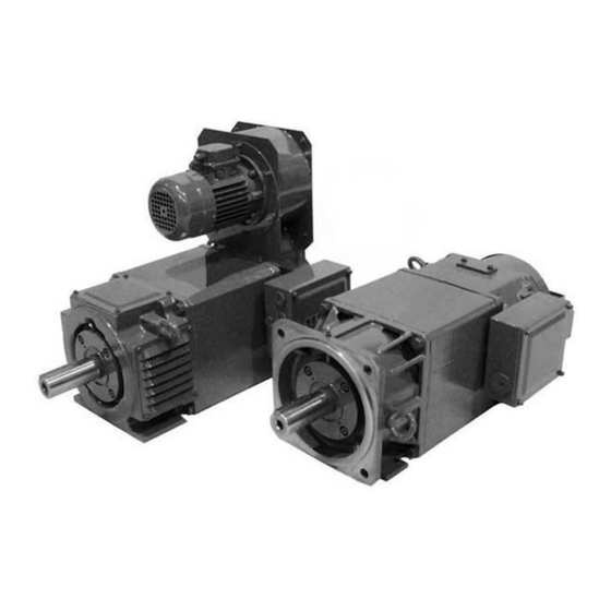
General Information Brusatori proposes a series of square frame ac motors for variable speed drives applications. This asynchronous motor has been developed and designed to achieve the same dynamic performance as for DC motors series. The AC square motor complies with IEC60034 standards and responds to the requirements for most industrial applications. -
Page 8: Operating Torque/Power Curves
Operating torque/power curves User’s manual - VF Series - vers. VF02.06.EN (09-2024) -
Page 9: Technical Data
Technical data Main features Insulation Class H Temperature rise Class F Thermal protection PTC 150 °C triplex Vibration and balancing Class A Class B (optional) Protection degree IP 23 IP 54/55 Cooling 3-phase fan blower: Radial mounting for IP 23 Axial mounting for IP 54 Axial or radial mounting for IP 55 Mounting... -
Page 10: Permissible Radial Loads
100Hz for a bearing life of 20000 hours. The motors are mounted on IM B3 foot in horizontal position. Ball bearings: Distance from shaft Type Speed 1500 rpm (N) Speed 3000 rpm (N) shoulder (mm) VF160 3500 2500 VF180 4000 3000 VF225 7000... -
Page 11: Optional Features
Optional features Size Cooling forms IC06 (IP23) Force ventilated IC17 (IP23) Single pipe ventilated IC37 (IP54) Double pipe ventilated IC416 (IP54) Totally enclosed, fan cooled Other cooling forms available on request Mounting Forms IM1001 Horizontal foot (radial ventilation) IM1001 Horizontal foot (axial ventilation) IM1002 Horizontal foot, double shaft extension IM2001 Horizontal foot and flange (radial ventilation) -
Page 12: Vibration Class And Balancing
Vibration class and balancing VF motors are manufactured as standard to meet vibration class A and balanced with half key. Class B is available on request. Vibrations are expressed in mm/s, rms, using free suspension method and measured under no load. Center height (mm) 160 <... -
Page 13: Duty Type Correction Factors
Duty type correction factors Motor power output can be increased depending on duty types defined by IEC 60034-1. Correction factors are given in the table below: Duty Operating time Continuous - Reference duty for nominal values Duty Operating time 10 min 30 min 60 min Duty... -
Page 14: Flange Dimensions
3.10 Flange dimensions On request VF motors can be equipped with integrated or bolted flange View View Flange size F300* 130* F350** F400 F300 F350** F400 F400 F500 F600 F400 F500 F600 F740 F500 F600 F740 F600 F740 * Special shaft required - C dimension change from 108 to 130 AV : Axial ventilation Technical and economical analysis is requested RV : Radial ventilation... -
Page 15: Datasheet Ip23 Version
Datasheet IP23 version 4.1 Electrical data VF 160 (S-M-L) IP23 motors Degree of Protection IP 23 Cooling IC 06 Sound Pressure level (db(A)) Rotor Inertia J (kgm2) S 0,24 - M 0,29 - L 0,33 at 50 Hz 3400 VF 160 S VF 160 S (9500)* Maximum mechanical speed... -
Page 16: Electrical Data Vf 180 (S-M-L) Ip23 Motors
4.2 Electrical data VF 180 (S-M-L) IP23 motors Degree of Protection IP 23 Cooling IC 06 Sound Pressure level (db(A)) Rotor Inertia J (kgm2) S 0,54 - M 0,74 - L 0,94 at 50 Hz 3200 VF 180 S VF 180 S (8500)* Maximum mechanical speed 3200... -
Page 17: Electrical Data Vf 225 (S-M-L) Ip23 Motors
4.3 Electrical data VF 225 (S-M-L) IP23 motors Degree of Protection IP 23 Cooling IC 06 Sound Pressure level (db(A)) Rotor Inertia J (kgm2) S 1,72 - M 2,29 - L 2,55 at 50 Hz 3800 VF 225 S VF 225 S (6500)* Maximum mechanical speed 3800... -
Page 18: Electrical Data Vf 250 (S-M-L) Ip23 Motors
4.4 Electrical data VF 250 (S-M-L) IP23 motors Degree of Protection IP 23 Cooling IC 06 Sound Pressure level (db(A)) Rotor Inertia J (kgm2) S 2,8 - M 3,4 - L 3,8 at 50 Hz 3400 VF 250 S VF 250 S 1090 (5700)* Maximum mechanical speed... -
Page 19: Electrical Data Vf 280 (S-M-L-P) Ip23 Motors
4.5 Electrical data VF 280 (S-M-L-P) IP23 motors Degree of Protection IP 23 S Cooling IC 06 S 4,17 - M 5,5 - L 6,2 Sound Pressure level (db(A)) Rotor Inertia J (kgm2) - P 6,7 at 50 Hz 3200 VF 280 S VF 280 S 1160... - Page 20 VF 280 L Rated speed 1000 1200 1500 1800 2000 Rated power Torque at rated speed 3705 3648 3573 3508 3438 3228 Current at rated power 1146 1196 n1 Maximum speed at constant power 1600 1920 2400 2880 3200 cos φ 0,84 0,85 0,85...
-
Page 21: Electrical Data Vf 315 (S-M-L-P) Ip23 Motors
4.6 Electrical data VF 315 (S-M-L-P) IP23 motors Degree of Protection IP 23 S Cooling IC 06 S 12,9 - M 16,1 - L 18,65 Sound Pressure level (db(A)) Rotor Inertia J (kgm2) - P 16,5 at 50 Hz 3000 VF 315 S VF 315 S 2140... - Page 22 VF 315 L Rated speed 1000 1200 1500 1800 2000 Rated power 1058 1104 Torque at rated speed 6074 5959 5841 5730 5613 5272 Current at rated power 1152 1326 1573 1850 1930 n1 Maximum speed at constant power 1600 1920 2400 2600...
-
Page 23: Electrical Data Vf 355 (S-M-L) Ip23 Motors
4.7 Electrical data VF 355 (S-M-L) IP23 motors Degree of Protection IP 23 Cooling IC 06 S 17,26 -M 22,32 - L 25,7 Sound Pressure level (db(A)) Rotor Inertia J (kgm2) - P 33,45 - X 41,2 at 50 Hz 2800 VF 355 S VF 355 S... - Page 24 VF 355 L Rated speed 1000 1200 1500 1800 2000 Rated power 1000 1176 1227 Torque at rated speed 6749 6618 6494 6367 6239 5857 Current at rated power 1265 1457 1728 2032 2120 n1 Maximum speed at constant power 1600 1920 2400...
-
Page 25: Dati Elettrici Versione Ip54/Ip55
Dati elettrici versione IP54/IP55 5.1 Electrical data VF 160 (S-M-L) IP54/IP55 motors Degree of Protection IP 55 Cooling IC 416 Sound Pressure level (db(A)) Rotor Inertia J (kgm2) S 0,24 - M 0,29 - L 0,33 at 50 Hz 3400 VF 160 S VF 160 S (5600)*... -
Page 26: Electrical Data Vf 180 (S-M-L) Ip54/Ip55 Motors
5.2 Electrical data VF 180 (S-M-L) IP54/IP55 motors Degree of Protection IP54/IP 55 Cooling IC 416 Sound Pressure level (db(A)) Rotor Inertia J (kgm2) S 0,54 - M 0,74- L 0,94 at 50 Hz 3200 VF 180 S VF 180 S (5300)* Maximum mechanical speed 3200... -
Page 27: Electrical Data Vf 225 (S-M-L) Ip55 Motors
5.3 Electrical data VF 225 (S-M-L) IP55 motors Degree of Protection IP 55 Cooling IC 416 Sound Pressure level (db(A)) Rotor Inertia J (kgm2) S 1,72 - M 2,29 - L 2,55 at 50 Hzv VF 225 S 3800 VF 225 S Maximum mechanical speed VF 225 M 3800... -
Page 28: Electrical Data Vf 250 (S-M-L) Ip55 Motors
5.4 Electrical data VF 250 (S-M-L) IP55 motors Degree of Protection IP 55 Cooling IC 416 Sound Pressure level (db(A)) Rotor Inertia J (kgm2) S 2,8 - M 3,4 - L 3,8 at 50 Hz 3400 VF 250 S VF 250 S 1110 (4200)* Maximum mechanical speed... -
Page 29: Electrical Data Vf 280 (S-M-L-P) Ip55 Motors
5.5 Electrical data VF 280 (S-M-L-P) IP55 motors Degree of Protection IP 55 Cooling IC 416 S 4,17 - M 5,5 - L 6,2 Sound Pressure level (db(A)) Rotor Inertia J (kgm2) - P 6,7 at 50 Hz 3200 VF 280 S VF 280 S 1180 (4000)*... - Page 30 VF 280 L Rated speed 1000 1200 1500 1800 2000 Rated power Torque at rated speed 1967 1929 1894 1859 1820 1709 Current at rated powe n1 Maximum speed at constant power 1000 2000 2400 2600 3100 3400* cos φ 0,84 0,85 0,85...
-
Page 31: Electrical Data Vf 315 (S-M-L-P) Ip55 Motors
5.6 Electrical data VF 315 (S-M-L-P) IP55 motors Degree of Protection IP 55 Cooling IC 416 S 12,9 - M 16,1 - L 18,65 Sound Pressure level (db(A)) Rotor Inertia J (kgm2) - P 16,5 at 50 Hz 3000 VF 315 S VF 315 S 2140 (3400)*... - Page 32 VF 315 L Rated speed 1000 1200 1500 1800 2000 Rated power Torque at rated speed 3343 3276 3215 3152 3088 2898 Current at rated power 1017 1061 n1 Maximum speed at constant power 1000 2000 2400 2600 2600 2600 cos φ...
-
Page 33: Electrical Data Vf 355 (S-M-L-P) Ip55 Motors
5.7 Electrical data VF 355 (S-M-L-P) IP55 motors Degree of Protection IP 55 Cooling IC 416 S 17,26 -M 22,32 - L 25,7 Sound Pressure level (db(A)) Rotor Inertia J (kgm2) - P 33,45 at 50 Hz 2800 VF 355 S VF 355 S 2130 (3000)*... - Page 34 VF 355 L Rated speed 1000 1200 1500 1800 2000 Rated power Torque at rated speed 3705 3639 3565 3502 3427 3223 Current at rated power 1116 1167 n1 Maximum speed at constant power 1000 2000 2400 2600 3000* 3000* cos φ...
-
Page 35: Mechanical Dimensions
Mechanical dimensions Mechanical dimensions IP23 6.1.1 Motor dimensions VF 160 S IP23 User’s manual - VF Series - vers. VF02.06.EN (09-2024) -
Page 36: Motor Dimensions Vf 160 M Ip23
6.1.2 Motor dimensions VF 160 M IP23 User’s manual - VF Series - vers. VF02.06.EN (09-2024) -
Page 37: Motor Dimensions Vf 160 L Ip23
6.1.3 Motor dimensions VF 160 L IP23 User’s manual - VF Series - vers. VF02.06.EN (09-2024) -
Page 38: Motor Dimensions Vf 180 S Ip23
6.1.4 Motor dimensions VF 180 S IP23 User’s manual - VF Series - vers. VF02.06.EN (09-2024) -
Page 39: Motor Dimensions Vf 180 M Ip23
6.1.5 Motor dimensions VF 180 M IP23 User’s manual - VF Series - vers. VF02.06.EN (09-2024) -
Page 40: Motor Dimensions Vf 180 L Ip23
6.1.6 Motor dimensions VF 180 L IP23 User’s manual - VF Series - vers. VF02.06.EN (09-2024) -
Page 41: Motor Dimensions Vf 225 S Ip23
6.1.7 Motor dimensions VF 225 S IP23 User’s manual - VF Series - vers. VF02.06.EN (09-2024) -
Page 42: Motor Dimensions Vf 225 M Ip23
6.1.8 Motor dimensions VF 225 M IP23 User’s manual - VF Series - vers. VF02.06.EN (09-2024) -
Page 43: Motor Dimensions Vf 225 L Ip23
6.1.9 Motor dimensions VF 225 L IP23 User’s manual - VF Series - vers. VF02.06.EN (09-2024) -
Page 44: Motor Dimensions Vf 250 S Ip23
6.1.10 Motor dimensions VF 250 S IP23 User’s manual - VF Series - vers. VF02.06.EN (09-2024) -
Page 45: Motor Dimensions Vf 250 M Ip23
6.1.11 Motor dimensions VF 250 M IP23 User’s manual - VF Series - vers. VF02.06.EN (09-2024) -
Page 46: Motor Dimensions Vf 250 L Ip23
6.1.12 Motor dimensions VF 250 L IP23 User’s manual - VF Series - vers. VF02.06.EN (09-2024) -
Page 47: Motor Dimensions Vf 280 S Ip23
6.1.13 Motor dimensions VF 280 S IP23 User’s manual - VF Series - vers. VF02.06.EN (09-2024) -
Page 48: Motor Dimensions Vf 280 M Ip23
6.1.14 Motor dimensions VF 280 M IP23 User’s manual - VF Series - vers. VF02.06.EN (09-2024) -
Page 49: Motor Dimensions Vf 280 L Ip23
6.1.15 Motor dimensions VF 280 L IP23 User’s manual - VF Series - vers. VF02.06.EN (09-2024) -
Page 50: Motor Dimensions Vf 280 P Ip23
6.1.16 Motor dimensions VF 280 P IP23 User’s manual - VF Series - vers. VF02.06.EN (09-2024) -
Page 51: Motor Dimensions Vf 315 S Ip23
6.1.17 Motor dimensions VF 315 S IP23 User’s manual - VF Series - vers. VF02.06.EN (09-2024) -
Page 52: Motor Dimensions Vf 315 M Ip23
6.1.18 Motor dimensions VF 315 M IP23 User’s manual - VF Series - vers. VF02.06.EN (09-2024) -
Page 53: Motor Dimensions Vf 315 L Ip23
6.1.19 Motor dimensions VF 315 L IP23 User’s manual - VF Series - vers. VF02.06.EN (09-2024) -
Page 54: Motor Dimensions Vf 315 P Ip23
6.1.20 Motor dimensions VF 315 P IP23 User’s manual - VF Series - vers. VF02.06.EN (09-2024) -
Page 55: Motor Dimensions Vf 355 S Ip23
6.1.21 Motor dimensions VF 355 S IP23 User’s manual - VF Series - vers. VF02.06.EN (09-2024) -
Page 56: Motor Dimensions Vf 355 M Ip23
6.1.22 Motor dimensions VF 355 M IP23 User’s manual - VF Series - vers. VF02.06.EN (09-2024) -
Page 57: Motor Dimensions Vf 355 L Ip23
6.1.23 Motor dimensions VF 355 L IP23 User’s manual - VF Series - vers. VF02.06.EN (09-2024) -
Page 58: Motor Dimensions Vf 355 P Ip23
6.1.24 Motor dimensions VF 355 P IP23 User’s manual - VF Series - vers. VF02.06.EN (09-2024) -
Page 59: Motor Dimensions Vf 355 X Ip23
6.1.25 Motor dimensions VF 355 X IP23 User’s manual - VF Series - vers. VF02.06.EN (09-2024) -
Page 60: Mechanical Dimensions Ip54
Mechanical dimensions IP54 6.2.1 Motor dimensions VF 160 S IP54 User’s manual - VF Series - vers. VF02.06.EN (09-2024) -
Page 61: Motor Dimensions Vf 160 M Ip54
6.2.2 Motor dimensions VF 160 M IP54 User’s manual - VF Series - vers. VF02.06.EN (09-2024) -
Page 62: Motor Dimensions Vf 160 L Ip54
6.2.3 Motor dimensions VF 160 L IP54 User’s manual - VF Series - vers. VF02.06.EN (09-2024) -
Page 63: Motor Dimensions Vf 180 S Ip54
6.2.4 Motor dimensions VF 180 S IP54 User’s manual - VF Series - vers. VF02.06.EN (09-2024) -
Page 64: Motor Dimensions Vf 180 M Ip54
6.2.5 Motor dimensions VF 180 M IP54 User’s manual - VF Series - vers. VF02.06.EN (09-2024) -
Page 65: Motor Dimensions Vf 180 L Ip54
6.2.6 Motor dimensions VF 180 L IP54 User’s manual - VF Series - vers. VF02.06.EN (09-2024) -
Page 66: Mechanical Dimensions Ip55
Mechanical dimensions IP55 6.3.1 Motor dimensions VF 160 S IP55 axial version User’s manual - VF Series - vers. VF02.06.EN (09-2024) -
Page 67: Motor Dimensions Vf 160 S Ip55 Radial Version
6.3.2 Motor dimensions VF 160 S IP55 radial version User’s manual - VF Series - vers. VF02.06.EN (09-2024) -
Page 68: Motor Dimensions Vf 160 M Ip55 Axial Version
6.3.3 Motor dimensions VF 160 M IP55 axial version User’s manual - VF Series - vers. VF02.06.EN (09-2024) -
Page 69: Motor Dimensions Vf 160 M Ip55 Radial Version
6.3.4 Motor dimensions VF 160 M IP55 radial version User’s manual - VF Series - vers. VF02.06.EN (09-2024) -
Page 70: Motor Dimensions Vf 160 L Ip55 Axial Version
6.3.5 Motor dimensions VF 160 L IP55 axial version User’s manual - VF Series - vers. VF02.06.EN (09-2024) -
Page 71: Motor Dimensions Vf 160 L Ip55 Radial Version
6.3.6 Motor dimensions VF 160 L IP55 radial version User’s manual - VF Series - vers. VF02.06.EN (09-2024) -
Page 72: Motor Dimensions Vf 180 S Ip55 Axial Version
6.3.7 Motor dimensions VF 180 S IP55 axial version User’s manual - VF Series - vers. VF02.06.EN (09-2024) -
Page 73: Motor Dimensions Vf 180 S Ip55 Radial Version
6.3.8 Motor dimensions VF 180 S IP55 radial version User’s manual - VF Series - vers. VF02.06.EN (09-2024) -
Page 74: Motor Dimensions Vf 180 M Ip55 Axial Version
6.3.9 Motor dimensions VF 180 M IP55 axial version User’s manual - VF Series - vers. VF02.06.EN (09-2024) -
Page 75: Motor Dimensions Vf 180 M Ip55 Radial Version
6.3.10 Motor dimensions VF 180 M IP55 radial version User’s manual - VF Series - vers. VF02.06.EN (09-2024) -
Page 76: Motor Dimensions Vf 180 L Ip55 Axial Version
6.3.11 Motor dimensions VF 180 L IP55 axial version User’s manual - VF Series - vers. VF02.06.EN (09-2024) -
Page 77: Motor Dimensions Vf 180 L Ip55 Radial Version
6.3.12 Motor dimensions VF 180 L IP55 radial version User’s manual - VF Series - vers. VF02.06.EN (09-2024) -
Page 78: Motor Dimensions Vf 225 S Ip55 Axial Version
6.3.13 Motor dimensions VF 225 S IP55 axial version User’s manual - VF Series - vers. VF02.06.EN (09-2024) -
Page 79: Motor Dimensions Vf 225 S Ip55 Radial Version
6.3.14 Motor dimensions VF 225 S IP55 radial version User’s manual - VF Series - vers. VF02.06.EN (09-2024) -
Page 80: Motor Dimensions Vf 225 M Ip55 Axial Version
6.3.15 Motor dimensions VF 225 M IP55 axial version User’s manual - VF Series - vers. VF02.06.EN (09-2024) -
Page 81: Motor Dimensions Vf 225 M Ip55 Radial Version
6.3.16 Motor dimensions VF 225 M IP55 radial version User’s manual - VF Series - vers. VF02.06.EN (09-2024) -
Page 82: Motor Dimensions Vf 225 L Ip55 Axial Version
6.3.17 Motor dimensions VF 225 L IP55 axial version User’s manual - VF Series - vers. VF02.06.EN (09-2024) -
Page 83: Motor Dimensions Vf 225 L Ip55 Radial Version
6.3.18 Motor dimensions VF 225 L IP55 radial version User’s manual - VF Series - vers. VF02.06.EN (09-2024) -
Page 84: Motor Dimensions Vf 250 S Ip55 Radial Version
6.3.19 Motor dimensions VF 250 S IP55 radial version User’s manual - VF Series - vers. VF02.06.EN (09-2024) -
Page 85: Motor Dimensions Vf 250 M Ip55 Radial Version
6.3.20 Motor dimensions VF 250 M IP55 radial version User’s manual - VF Series - vers. VF02.06.EN (09-2024) -
Page 86: Motor Dimensions Vf 250 L Ip55 Radial Version
6.3.21 Motor dimensions VF 250 L IP55 radial version User’s manual - VF Series - vers. VF02.06.EN (09-2024) -
Page 87: Motor Dimensions Vf 280 S Ip55 Radial Version
6.3.22 Motor dimensions VF 280 S IP55 radial version User’s manual - VF Series - vers. VF02.06.EN (09-2024) -
Page 88: Motor Dimensions Vf 280 M Ip55 Radial Version
6.3.23 Motor dimensions VF 280 M IP55 radial version User’s manual - VF Series - vers. VF02.06.EN (09-2024) -
Page 89: Motor Dimensions Vf 280 L Ip55 Radial Version
6.3.24 Motor dimensions VF 280 L IP55 radial version User’s manual - VF Series - vers. VF02.06.EN (09-2024) -
Page 90: Motor Dimensions Vf 280 P Ip55 Radial Version
6.3.25 Motor dimensions VF 280 P IP55 radial version User’s manual - VF Series - vers. VF02.06.EN (09-2024) -
Page 91: Motor Dimensions Vf 315 S Ip55 Radial Version
6.3.26 Motor dimensions VF 315 S IP55 radial version User’s manual - VF Series - vers. VF02.06.EN (09-2024) -
Page 92: Motor Dimensions Vf 315 M Ip55 Radial Version
6.3.27 Motor dimensions VF 315 M IP55 radial version User’s manual - VF Series - vers. VF02.06.EN (09-2024) -
Page 93: Motor Dimensions Vf 315 L Ip55 Radial Version
6.3.28 Motor dimensions VF 315 L IP55 radial version User’s manual - VF Series - vers. VF02.06.EN (09-2024) -
Page 94: Motor Dimensions Vf 315 P Ip55 Radial Version
6.3.29 Motor dimensions VF 315 P IP55 radial version User’s manual - VF Series - vers. VF02.06.EN (09-2024) -
Page 95: Motor Dimensions Vf 355 S Ip55 Radial Version
6.3.30 Motor dimensions VF 355 S IP55 radial version User’s manual - VF Series - vers. VF02.06.EN (09-2024) -
Page 96: Motor Dimensions Vf 355 M Ip55 Radial Version
6.3.31 Motor dimensions VF 355 M IP55 radial version User’s manual - VF Series - vers. VF02.06.EN (09-2024) -
Page 97: Motor Dimensions Vf 355 L Ip55 Radial Version
6.3.32 Motor dimensions VF 355 L IP55 radial version User’s manual - VF Series - vers. VF02.06.EN (09-2024) -
Page 98: Motor Dimensions Vf 355 P Ip55 Radial Version
6.3.33 Motor dimensions VF 355 P IP55 radial version User’s manual - VF Series - vers. VF02.06.EN (09-2024) -
Page 99: Electrical Connections
7. Electrical connections 7.1 Safety Instructions WARNING! Do not perform work on the motor, connecting cables, frequency converters or accessories such as brakes, fans or thermal protection cables when voltage is present. WARNING! For cable entries, use cable glands and seals that conform to the type of protection and cable diameter. -
Page 100: Transducer (Encoder)
The required tightening torque according to the pin type is given below: Pin size Tightening torque [Nm] WARNING! Tighten the cables on the headstocks observing the tightening torques corresponding to the pin type. Tolerance +0% / -10% 7.2 Transducer (Encoder) Normally, a hollow-shaft transducer is used on VF series motors. -
Page 101: Thermal Protector
Wiring instructions for the signal flying connector are illustrated on a sheet located inside the motor terminal box. Always use a shielded cable for connection to the inverter. When soldering the flying connector, do not overheat the contacts. Avoid short circuits between the connector contacts. WARNING! Failure to comply with any of the above warnings may result in immediate failure of the encoder. -
Page 102: Transportation And Storage
Do not use the hooks if the temperature is below -20°C. All the motors manufactured by Brusatori leave the factory in optimal conditions after being inspected and tested. Upon arrival, check the motor carefully to ensure that it has not been damaged during transport. -
Page 103: Installation
9. Installation 9.1 Mounting WARNING! The motors are designed exclusively for installation in industrial environments. Different installations are permitted only if all necessary precautions are taken by the machine/plant manufacturer to ensure safe operation. Read the entire manual carefully before performing any operation. Any installation operation must be carried out by qualified personnel, with tools appropriate to the type of operation. -
Page 104: Ventilation
WARNING! Excessive belt tension can cause rapid bearing wear and shaft failure. Attach or remove drive elements (pulley, coupling, gear wheel, etc.) only with appropriate devices (for example, heating the drive element or using the threaded hole on the shaft end). WARNING! Never fit half couplings or pulleys using a hammer, or remove them using a lever infulcated against the motor body. -
Page 105: Commissioning
9.3 Commissioning The following points should be checked before commissioning: The rotor must be able to rotate freely (supply the brake if necessary). The correct installation of the drive elements must be checked. All electrical connections and connecting elements must be carefully made and tightened. The protective and grounding conductor must be properly connected. -
Page 106: Maintenance
10. Maintenance 10.1 Instructions on maintenance WARNING! Before starting any work on the motors and before opening any cover of active parts, be sure Cut the power to the motor. Blocking re-insertion. Verify that there is no voltage. Check for proper grounding. Cover or separate adjacent live parts. -
Page 107: Troubleshooting
Unprotected machined surfaces (flanges and shaft ends) should be treated with anticorrosive products. Cleaning the motor can damage it if done incorrectly. Use only appropriate products. Avoid contact of products with oil seals and gaskets to prevent damage. 10.1 Troubleshooting Note: This list cannot be considered complete. -
Page 108: Disposal
Directive. 12.3 Dichiarazione UE di Conformità Most recent version of the Declaration of Conformity can be found on Brusatori website. 12.4 Sistema di gestione per la qualità ISO 9001:2015 Most recent version of the document can be found on Brusatori website. - Page 109 Notes User’s manual - VF Series - vers. VF02.06.EN (09-2024)
- Page 110 Via Meucci 5/7 20012 Cuggiono (MI) Italy Tel: (0039) 02-25068401 Fax: (0039) 02-25060140 Web: http://www.brusatori.eu/ Mail: info@brusatori.eu User’s manual - VF Series - vers. VF02.06.EN (09-2024)
Need help?
Do you have a question about the VF160 and is the answer not in the manual?
Questions and answers