Advertisement
Quick Links
Advertisement

Related Manuals for Seeley Braemar Ecostar SH18


Summary of Contents for Seeley Braemar Ecostar SH18
- Page 1 Space Heater. SH18 & SH25 WF25. 2019...
- Page 2 Braemar Ecostar Space Heater SH25 and SH18 WF25 Wall Furnace Training 2012...
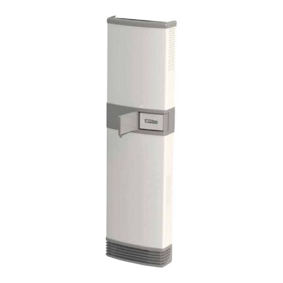
- Page 3 WF25 Wall Furnace SH18,SH25 Space Heater...
- Page 4 ONE heater…simple push-button controls Space Heater Universal Controller ( SHUC)
- Page 5 SPECIFICATIONS GAS SPECIFICATIONS GAS TYPE SH18 SH25/WF25 Natural Gas (HIGH) Nominal Gas Input rate (MJ/h) Natural Gas (LOW) Propane Nominal Thermal Output (kW) Natural Gas - High 1000 1000 Natural Gas - Low Test Point Pressure (Pa) Propane - High 1700 2000 Propane - Low...
- Page 6 SHUC OPERATION When using the remote you can set temperatures down to ZERO degrees and above 28 degrees, as stated for the Space Heater User Control. (SHUC = 16 to 28...
- Page 7 MAJOR COMPONENTS...
- Page 8 INSIDE THE HEATER...
- Page 10 INSTALLATION OPTIONS SH18,SH25...
- Page 11 INSTALLATION OPTIONS WF25 Flexible Installation Options WF25 Installation Location External Wall External Wall External Wall External Wall Internal Wall Internal Wall Internal Wall Internal Wall Vertical Flue Kit Inbuilt Inbuilt Console Console Inbuilt Console Inbuilt Console Flue type Horizontal Flue Vertical Flue Horizontal Flue Vertical Flue...
- Page 12 INSTALLATION KITS AND OPTIONS...
- Page 13 FLUE SYSTEMS Co-axial flue • Combustion products flow out through inside tube • Combustion air drawn in through outer tube • MUST USE BRAEMAR FLUE KIT AND FITTINGS •FLUE KITS MUST NOT BE MODIFIED IN ANY WAY Vertical flue Flue outlet Combustion air inlet Horizontal flue...
- Page 14 OPTIONAL KITS - FLUES WALL FLUE Horizontal flue...
- Page 15 Temperature readings of SPACE HEATER HORIZONTAL - flue system. 8th August 2013 By TPC Temperatures within "HORIZONTAL" Flue System. Ambient = 14 o C Normal running. OT Shut Down. 75 o C 112 o C 4: Room Air = 100 o C 115 o C Flue 75 o C...
- Page 16 WALL CAVITY FLUE SYSTEM • Maximum vertical flue length is 6m specified in the flue kit instructions – • Wall cavity kits are: • Standard wall cavity flue kit – includes 3.6m flue (suits 2.4m ceiling height and approximately 1.2m roof space) •...
- Page 17 OPTIONAL KITS - FLUES CAVITY FLUE Flue outlet Combustion air inlet CO-AXIAL FLUE OFFSET SHORT Kit P/No: 089997...
- Page 18 Temperature readings of SPACE HEATER VERTICAL - flue system. 8th August 2013 By TPC Temperatures in & around FLUE TERMINAL. Ambient = 10 Normal running. OT Shut Down. 80 o C 111 o C : Room Air = 67 o C 80 o C Flue 1000mm...
- Page 19 OPTIONAL KITS CONTROLLERS When using the remote/wall control you can set temperatures down to ZERO degrees and above 28 degrees. Space Heater User Control. (Setting temperatures) (SHUC = 16 to 28 RF (SCC) remote control kit Part number 093086...
- Page 20 OPTIONAL KITS CONTROLLERS (RF SCC & RF INTERFACE) • RF SCC and RF interface board are factory matched • Instructions for matching if replacing either component are included. • NOT available as individual items MATCHED RF Interface PAIR...
- Page 21 OPTIONAL KITS REAR REGISTER Rear register kit Part number 093109...
- Page 22 OPTIONAL KIT Console Kit Console Kit WF25 Standard – suits ceiling height up to 3m : Part No. 089973 Long – suits ceiling height up to 3.6m : Part No. 089980 Converts standard cover to suit console installation and covers flue to ceiling height Console Kit SH18/25 SH25 Part No.:092973...
- Page 24 CONNECTIONS ‡ 1/2” male copper flare at gas valve inlet OT2 = GH-262 - SWITCH O/T 60 Deg AUTO NEW Position OLD Position ELECTRICITY ‡ 240 Vac GPO within: ‡ 900mm from left, or ‡ 500mm from right OT1 = 611518 - SWITCH O/T 80 Deg AUTO...
- Page 25 INSTALLATION – HEATER LOCATION...
- Page 26 INSTALLATION - INBUILT HORIZONTAL FLUE VERTICAL FLUE...
- Page 27 CONNECTING FLUE...
- Page 28 Combustion gases Fresh air for combustion, discharged to outside drawn from outside. The combustion fan draws fresh air through the following path. 1) Through “PVC” tube from outside. 2) Through the rear duct of the heater to the burners. 3) Through HX tubes where combustion takes place. 4) Into combustion fan housing.
- Page 29 CONNECTING FLUE HORIZONTAL FLUE...
- Page 30 CONNECTING FLUE VERTICAL FLUE...
- Page 31 COMMISIONING...
- Page 32 PRODUCT IMPROVEMENT CHANGES 45 Pa pressure switch removed • Heater now operates with only one pressure switch - PS-18 • This is the one with the red and purple wires and is connected to the Fenwal EFS (the 45 Pa switch was the one with the blue and yellow wires connected in line with the high/low coil on the gas valve) •...
- Page 33 PRODUCT UPDATE Issue #35 1st June 2012 www.braemar.net.au SAFETY ALERT PRODUCT IMPROVEMENT QUALITY ALERT Change to SH18, SH25 and WF25 Pressure switch from Goldtech to Cleveland Bracket Pre SN S12060027. Goldtech switch 639826 (coloured black with bracket) was mounted to bracket as (indicated).
- Page 34 PRESSURE SWITCH function - SH18, SH25 & WF25. Flue system - STATUS. Flue Measured at Measured at Heater length 0.5 meters in length. Combustion Co Ax Box. Fan. Inlet Air Differential (Horizontal) Function. (Pa) (Pa) (Pa) All Clear (No Obstructions.) OUTLET 50% blocked.
- Page 37 PRODUCT IMPROVEMENT CHANGES Overtemp relocation • To minimise the chance of nuisance tripping of HX OT2 resulting in possible FC11,FC16 and FC19 fault codes , the OT2 switch it has been relocated from the front panel just above the heat exchanger •...
- Page 40 SPACE HEATER SH18/SH25 - WIRING DIAGRAM BROWN BRAEMAR GAS SPACE HEATER BROWN BROWN MODELS SH18 & SH25 BLUE COMBUSTION WIRING DIAGRAM BLUE ROOM BROWN GREEN/YELLOW GREEN YELLOW TRANSFORMER ROOM FAN MAINS LEAD GREEN/YELLOW 240 Vac 50 Hz SUPPLY BLUE BROWN PINK PINK PURPLE...
- Page 41 HEATER OPERATION - START Unit turned ON = Green LED on main board START SEQUENCE SUMMARY Call for heat = Red LED on main board. ‡ Call for heat ‡ Check pressure switch is open ‡ Check OT1 closed ‡ Start combustion fan on high ‡...
- Page 42 START SEQUENCE FLOWCHART GREEN LED on main PCBA START RED LED on main PCBA Thermostat calls for heat Record fault. 1 Check P-18 open ? To lockout 1. 15 to 20 seconds Record fault. 10 Check OT1 closed ? To lockout 1. Start combustion fan on high If PS-low fails to close after 3 x 1 minute Check PS-18 closed ?
- Page 43 HEATER OPERATION - RUN RUN MODE SUMMARY • Start room fan on low 15 sec after gas on • Check pressure switch is closed • Check OT1 closed • Check flame signal • Read room temperature • Read set temperature •...
- Page 44 RUN SEQUENCE FLOWCHART Space Heater TOTAL power usage. Test performed on the SH test station. 14th March 2018 By TPC & AG SH25 SH18 Check P-18 closed ? Record fault 3. @ - Standby. @ - Standby. Volts = 241 Volts = 241 Check OT1 closed ? Record fault 10.
- Page 45 THERMOSTAT OPERATION...
- Page 46 FAULT CODES...
- Page 47 FAULT CODE EXAMPLES • Fault code = sum of flashing red LED’s • Green LED flashing = lockout 1 • Green and orange LED flashing = lockout 2...
- Page 48 HEATER FRONT PANEL CONTROL SERVICE MODE TO ENTER SERVICE MODE: • Press and hold both up and down arrow buttons, and press ON/OFF button once to enter “service mode” TO DISPLAY THE LAST 4 RECORDED FAULT CODES: • When you enter service mode, the LED’s will display the latest recorded fault code –...
- Page 49 HEATER FRONT PANEL CONTROL SERVICE MODE TO CLEAR RECORDED FAULT CODES: • While in “service mode” press and hold the up and down arrow buttons for 5 seconds – this will also send a reset command to the heater • MAKE SURE ANY RECORDED FAULTS ARE CLEARED AFTER EVERY SERVICE The use of a DGH SPARKER and FLAME SENSE lead WILL cause...
- Page 50 FAULT CODES FC 1: PS-18 CLOSED AT START • Faulty pressure switch – contacts welded closed • Combustion fan on as soon as call for heat received – combustion fan relay contacts on Electronic Flame Sense (EFS) welded closed (FENWAL Relay) FC2: PS-18 FAILED TO CLOSE •...
- Page 51 FAULT CODES FC 5: THERMISTOR DISCONNECTED OR SHORT CIRCUIT • Room temperature thermistor disconnected or damaged FC7: IGNITION FAILURE • Failed to sense flame after 3 ignition attempts • Gas supply turned off • Incorrect gas pressure • Ignition or sense lead disconnected or damaged FC9: INTERNAL MEMORY FAILURE •...
- Page 52 FAULT CODES FC 10: OT1 OPEN • Reduced room air flow • Inlet and/or outlet air obstruction • Dust/lint on room fan FC11: FLAME FAILURE • Incorrect gas pressure • Air in gas line • OT2 opened during run due to room fan failure...
- Page 53 FAULT CODES FC15: MULTIPLE OT1 OPEN • OT1 has opened multiple times in one heating cycle • Reduced room air flow • Inlet and/or outlet air obstruction • Dust/lint on room fan FC16: OT2 OPEN AT START • Room fan not running •...
- Page 54 RF SCC – DOOR CLOSED ON/OFF • Turn heater on or off HOME/AWAY • Toggles between current and next time period in AUTO mode (wake/away/home/sleep) UP/DOWN ARROWS • Increase or decrease set temperature • Press once to display current set temperature •...
- Page 55 RF SCC – DOOR OPEN ON/OFF, HOME/AWAY • Same as door closed UP/DOWN ARROWS • Increase or decrease parameter being adjusted • Press once to display current set temperature • Press again to adjust set temperature • Press to force communication with heater (otherwise communication occurs every 2 to 3 minutes)
- Page 56 RF SCC – DOOR OPEN • Accepts value being adjusted PROG • Press once when in run or standby modes to enter user programming mode LOCK • Press to lock SCC controls – the only button that will still function is OFF MAN/AUTO •...
- Page 57 RF SCC – MANUAL AND AUTO MODE MANUAL MODE: • Turn heater on and off using ON/OFF button • Adjust set temperature using arrows AUTO MODE: • Allows start time and set temperature for 4 time periods per day to be programmed •...
- Page 58 RF SCC – USER PROGRAMMING • 4 Daily time periods : • WAKE – AWAY – HOME – SLEEP • Start time and room temperature can be set for each time period • With RF SCC in ON or STANDBY mode: •...
- Page 59 RF SCC COMMUNICATION • If heater is switched on using RF SCC, it communicates with heater and updates display if required every 2 to 3 minutes. it takes a few minutes to update it doesn’t mean it is broken. • If a button is pressed on RF SCC it communicates and updates immediately.
- Page 60 REMOTE ISSUES Problems include the following. The remote is turning itself to “OFF”, whether in “AUTO” or “MAN” mode. The RF Remotes will switch themselves to the OFF state after 50 to 60 minutes, if they do not receive regular signal from the Interface unit.
- Page 61 HEATER CONTROL & RF SCC LOCK FUNCTIONS • HEATER CONTROL PANEL and RF SCC can be locked and un-locked independently • HEATER CONTROL PANEL LOCKED (orange LED on) • Can switch heater OFF at heater control panel • Cannot switch back ON at heater control panel until heater control panel is unlocked •...
- Page 62 RF SCC SERVICE MODE SERVICE MODE FUNCTIONS: • Fault code retrieval • Run time high and low gas • Communication and software version check • Lockout 2 reset ENTER SERVICE MODE: • RF SCC in OFF state • Open RF SCC door •...
- Page 63 RF SCC SERVICE MODE FAULT CODE RETRIEVAL: • Press ON/OFF on SCC to turn SCC off • Open SCC door • Press and hold ‘door’ button and press SET • SCC displays latest stored fault code • Press UP/DOWN arrows to scroll through last 10 recorded fault codes •...
- Page 64 RF SCC SERVICE MODE HEATER RUN TIME: • Enter service mode • Run hours on high gas - press MAN/AUTO • Run hours on low gas – press ECO CLEARING HEATER RUN TIME: • While in service mode, hold MAN/AUTO and ECO down together for 3 seconds...
- Page 65 RF SCC SERVICE MODE COMMUNICATION CHECK: • Enter service mode • Press ‘LOCK’ button to initiate communications check • Display first shows RF SCC software version number, then ‘yes’ or ‘no’ to indicate communication status with heater...
- Page 66 Questions ? THANKYOU ALL FOR YOUR TIME.
- Page 67 Phone +61 8 8328 3850 Seeley International Pty Ltd +61 8 8328 3951 112 O’Sullivan Beach Road Lonsdale SA 5160 ABN 23 054 687 035 Australia seeleyinternational.com PO Box 164 Lonsdale SA 5160 Australia...
Need help?
Do you have a question about the Braemar Ecostar SH18 and is the answer not in the manual?
Questions and answers