Advertisement
Quick Links
SabreCom-300
Rugged Computer System
User Manual Rev. 1.3
For model no.: SC300-VNS776-20-LNX-EG8-L2-J5-01
Copyright 2024
FOR TECHNICAL SUPPORT
Diamond Systems Corporation
PLEASE CONTACT:
158 Commercial Street
Sunnyvale, CA 94086 USA
support@diamondsystems.com
Tel 1-650-810-2500
www.diamondsystems.com
Advertisement

Related Manuals for Diamond Systems SabreCom-300


Summary of Contents for Diamond Systems SabreCom-300
- Page 1 SabreCom-300 Rugged Computer System User Manual Rev. 1.3 For model no.: SC300-VNS776-20-LNX-EG8-L2-J5-01 Copyright 2024 FOR TECHNICAL SUPPORT Diamond Systems Corporation PLEASE CONTACT: 158 Commercial Street Sunnyvale, CA 94086 USA support@diamondsystems.com Tel 1-650-810-2500 www.diamondsystems.com...
- Page 2 ........................33 EVICE PTIONS 14.3 ......................33 NSTALLING OOTING 15. VIDEO FEATURES ......................... 34 16. SERIAL PORTS AND SYSTEM CONSOLE ................34 16.1 ..........................34 ONFIGURATION 16.2 ........................34 ONSOLE REDIRECTION SabreCom-300 User Manual rev 1.3 www.diamondsystems.com Page 2 of 34...
- Page 3 Safe Handling Precautions The list here describes common causes of failure found on boards returned to Diamond Systems for repair. This information is provided as a source of advice to help you prevent damaging your Diamond (or any vendor’s) embedded computer boards.
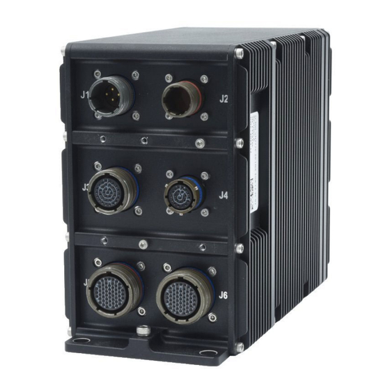
- Page 4 DESCRIPTION SabreCom-300 is a system enclosed in a rugged enclosure. It consists of an SBC with Intel Skylake i7 Series processor at its core. The system can be powered with 9-18V DC input power supplies. The system is equipped with a module to filter out EMI and suppress surges that come in on the power supply cable to a device receiving the power that could cause interference from that device or damage or destroy the device itself.
- Page 5 KEY SUBSYSTEMS 3.1 SBC The SBC in SabreCom-300 is Diamond’s Venus board, based on the 7th generation Intel Kaby lake processor i7- 7660U. The U-series processors are offered in a 1-chip platform that includes the 7th generation Intel Platform Controller Hub (PCH) die on the same package as the processor die. It is a dual core, 64 bit processor with a processor base frequency of 2.5GHz and maximum turbo frequency of 4GHz.
- Page 6 CONFIGURATION GUIDE SabreCom-300 can be configured for a large variety of features. A spreadsheet on the Diamond Systems website is used to select each available option and create an ordering part number and description: The available choices for each option may change from time to time. As of the release date of this manual, the...
- Page 7 An example part number and description selecting all default choices is as follows: System part number: SC300-VNS776-20-LNX-EG8-L2-J1-01 SabreCom-300, i7-7600U CPU, 20GB RAM, Linux, 8-Port Gbe Switch, Layer 2+ FW, System description: MIL Iso Power, 1TB SSD SabreCom-300 User Manual rev 1.3 www.diamondsystems.com...
- Page 8 55-pin D38999/26WE35PA connector on the front panel. 5.5 CAN Ports This model of SabreCom-300 provides 2 CAN interface through JANUS-MM-LP PC-104 adaptor. The CAN transceivers are Analog Devices ADM3053 with a combination of isolation and transceiver. The device is powered by +5V.
- Page 9 5.9 PCI-104 and One Bank PCIe/104 Expansion SabreCom-300 offers I/O expansion via a PCI-104 connector, a PCIe/104 OneBank connector, and a PCIe/USB minicard socket. A maximum of one minicard plus one PCI-104 OR PCIe/104 I/O module can be installed in the standard width enclosure.
- Page 10 SYSTEM ARCHITECTURE Figure 1 provides an overview of the block diagrarm of the SabreCom-300 system. Figure 1: System Architecture of SabreCom-300 Figure 2: Inner View of SabreCom-300 with Optional PCI-104 CAN I/O Expansion Module SabreCom-300 User Manual rev 1.3 www.diamondsystems.com...
- Page 11 SABRECOM - MECHANICAL DRAWING Dimensions in mm SabreCom-300 User Manual rev 1.3 www.diamondsystems.com Page 11 of 34...
- Page 12 2x USB2.0 Port 5-6 SJT00RT12-35DS014 1X HDMI 3x Gigabit Ethernet, Port 3-5 D38999/20WE35SN 2x RS422, Port 1-2 1x CAN Port-1 3x Gigabit Ethernet, Port 6-8 D38999/20WE35SN 2x RS422, Port 3-4 1x CAN Port-2 SabreCom-300 User Manual rev 1.3 www.diamondsystems.com Page 12 of 34...
- Page 13 The tables below show the pin assignments of all outward facing I/O connectors. Pin locations without any associated signal are no-connect pins. These pinout tables are specific to the model number of SabreCom-300 shown on the title page of this manual. Connector pinouts vary based on the product configuration.
- Page 14 RS422_RX2- RS422_RX4- From Venus From Venus RS422_RX2+ RS422_RX4+ SBC port 2 SBC port 4 RS422_TX2- RS422_TX4- RS422_TX2+ RS422_TX3+ CAN 1_H CAN 2_H CAN 1_L CAN 2_L CAN 1_GND CAN 2_GND SabreCom-300 User Manual rev 1.3 www.diamondsystems.com Page 14 of 34...
- Page 15 J4, HDMI (SJT00RT12-35DS014) 22 x #22 Pin Description HDMI_DP2_TX0_CON_P HDMI_DP2_TX0_CON_N HDMI_DP2_TX1_CON_P HDMI_DP2_TX1_CON_N HDMI_DP2_TX2_CON_P HDMI_DP2_TX2_CON_N HDMI_HPD_CON HDMI_DP2_TX3_CON_P HDMI_DP2_TX3_CON_N HDMI_SCL_CON HDMI_SDA_CON GND_DIG GND_DIG GND_DIG GND_DIG GND_DIG HDMI_CEC_CON V_5P0_HDMI GND_DIG SabreCom-300 User Manual rev 1.3 www.diamondsystems.com Page 15 of 34...
- Page 16 USB2.0P1D+ USB2.0P1Gnd USB2.0P2Vcc USB2.0P2D- From Venus SBC USB2.0 port 2 USB2.0P2D+ USB2.0P2Gnd BI_DC+_SBC_P2 BI_DC-_SBC_P2 From Venus SBC port 2 BI_DD+_SBC_P2 BI_DD-_SBC_P2 BI_DC+_P2 BI_DC-_P2 From Ethernet Switch port 2 BI_DD+_P2 BI_DD-_P2 SabreCom-300 User Manual rev 1.3 www.diamondsystems.com Page 16 of 34...
- Page 17 10. I/O CONNECTOR DETAIL These pinout specifications are specific to the model number of SabreCom-300 shown on the title page of this manual. Connector pinouts vary based on the product configuration. 10.1 J1: Power Input SabreCom-Venus provides a C-size D38999 series circular connector with pin terminals for power input.
- Page 18 10.2 J3: User Control IO SabreCom-300 provides 2x Ethernet, 2x USB 2.0 and one serial port on D38999 series circular connector. Function: Ethernet port 1-2, USB port 1-2, Serial debug port Enclosure location: J3 (Middle Left) connector Connector type MIL D38999/20WD35SN...
- Page 19 Port 1 USB2.0P1D+ Green Type A- Female USB2.0P1Gnd Black USB2.0P2Vcc Orange USB2.0 USB2.0P2D- Yellow Port 2 USB2.0P2D+ Blue Type A- Female USB2.0P2Gnd Brown Black TX1/TX1_P/RX1_P Black DB9-1 RX1/RX1_P Male GND_DIG SabreCom-300 User Manual rev 1.3 www.diamondsystems.com Page 19 of 34...
- Page 20 10.3 J4: HDMI Interface SabreCom-300 provides 1x HDMI, on SJT series circular connector. Function: HDMI Enclosure location: J4 (Middle Right) Connector description connector Connector type MIL SJT00RT12-35DS014 ternal Description Shell type Straight Plug Material and finish Flange receptacle with Shell Size...
- Page 21 External Connector connector Signal Type Pin no. HDMI_DP2_TX0_CON_P HDMI_DP2_TX0_CON_N GND_DIG HDMI_DP2_TX1_CON_P HDMI_DP2_TX1_CON_N GND_DIG HDMI_DP2_TX2_CON_P HDMI_DP2_TX2_CON_N GND_DIG HDMI HDMI_DP2_TX3_CON_P Female HDMI_DP2_TX3_CON_N GND_DIG HDMI_CEC_CON HDMI_SCL_CON HDMI_SDA_CON GND_DIG V_5P0_HDMI HDMI_HPD_CON GND_DIG GND_CHASSIS GND_CHASSIS SabreCom-300 User Manual rev 1.3 www.diamondsystems.com Page 21 of 34...
- Page 22 10.4 J5: Ethernet, CAN, Serial SabreCom-300 provides 3x Ethernet, 1x CAN, 2x Serial ports and these signals terminated on a E-sized D38999 series circular connector. All the above mentioned interfaces share the same connector. Function: Ethernet port 3-5, CAN port-1, Serial port 1-2...
- Page 23 BI_DA+_P5 White-Orange BI_DA-_P5 Orange BI_DB+_P5 White-Green BI_DB-_P5 Green RJ45 jack BI_DC+_P5 Blue BI_DC-_P5 White-Blue BI_DD+_P5 White-Brown BI_DD-_P5 Brown RS422_GND2 White RS422_RX2- Grey DB9-2 RS422_RX2+ Blue Male RS422_TX2- Purple RS422_TX2+ Green SabreCom-300 User Manual rev 1.3 www.diamondsystems.com Page 23 of 34...
- Page 24 RS422_GND1 Yellow RS422_RX1- Orange DB9-1 RS422_RX1+ Brown Male RS422_TX1- RS422_TX1+ Black CAN 1_GND CAN 1_L Brown DB9-3 CAN 1_H Blue Male SabreCom-300 User Manual rev 1.3 www.diamondsystems.com Page 24 of 34...
- Page 25 10.5 J6: Ethernet, CAN, Serial SabreCom-300 provides 3x Ethernet, 1x CAN, 2x Serial ports and these signals terminated on a E-sized D38999 series circular connector. All the above mentioned interfaces share the same connector. Function: Ethernet port 6-8, CAN port-2, Serial port 3-4...
- Page 26 White-Green RJ45 jack BI_DB-_P8 Green Ethernet BI_DC+_P8 Blue Port 8 BI_DC-_P8 White-Blue BI_DD+_P8 White-Brown BI_DD-_P8 Brown RS422_GND4 White RS422_RX4- Grey DB9-2 RS422_RX4+ Blue Male RS422_TX4- Purple RS422_TX4+ Green RS422_GND3 Yellow SabreCom-300 User Manual rev 1.3 www.diamondsystems.com Page 26 of 34...
- Page 27 RS422_RX3- DB9-1 Orange Male RS422_RX3+ Brown RS422_TX3- RS422_TX3+ Black CAN 2_GND CAN 2_L Brown DB9-3 CAN 2_H Blue Male SabreCom-300 User Manual rev 1.3 www.diamondsystems.com Page 27 of 34...
- Page 28 Serial Debug port HDMI SJTG06RT12-35DP014 Ethernet Port-3 Ethernet Port-4 Ethernet Port-5 D38999/26WE35SN CAN Port-1 Serial Port-1 Serial Port-2 Ethernet Port-6 Ethernet Port-7 Ethernet Port-8 D38999/26WE35SA CAN Port-2 Serial Port-3 Serial Port-4 SabreCom-300 User Manual rev 1.3 www.diamondsystems.com Page 28 of 34...
- Page 29 Jumper shunts. Figure 3: Jumper Blocks on Venus Carrier Board Jumper Block Functions Name Function SATA DOM Power, PCI VIO LVDS LCD VCC and Backlight SabreCom-300 User Manual rev 1.3 www.diamondsystems.com Page 29 of 34...
- Page 30 2. Reboot the CPU (reset or power-down and power-up). 3. Hold down the F3 key while the CPU is booting. 4. The board will boot up normally. The BIOS settings will be reset to their defaults. SabreCom-300 User Manual rev 1.3 www.diamondsystems.com Page 30 of 34...
- Page 31 5. Once booted to shell, identify which is the file system for USB flash disk. It can be fs0 or fs1 or fs2. You can check this by pressing page up button. 6. Assuming it is fs0:, follow the below commands. fs0: afuefix64.efi <BIOS_filename>.bin /b /p /n SabreCom-300 User Manual rev 1.3 www.diamondsystems.com Page 31 of 34...
- Page 32 Venus provides 4 serial ports. All 4 ports support RS-232/422/485 functionalities. The functionality can be configured from the BIOS GUI. In BIOS setup go to advanced menu then Serial/Parallel port configuration. Select the appropriate mode for the Serial Ports. SabreCom-300 User Manual rev 1.3 www.diamondsystems.com Page 32 of 34...
- Page 33 ♦ Upon successful installation, boot to Windows 10 and install the necessary drivers. ♦ For installing Windows 7 OS, special instructions need to be followed. Please contact DSC for the same. SabreCom-300 User Manual rev 1.3 www.diamondsystems.com Page 33 of 34...
- Page 34 Advanced settings menu, then in Remote Access Configuration enable the Remote access feature. Then select the serial port. User should see the BIOS setup menu in the PC console. SabreCom-300 User Manual rev 1.3 www.diamondsystems.com Page 34 of 34...
Need help?
Do you have a question about the SabreCom-300 and is the answer not in the manual?
Questions and answers