
Related Manuals for Fujitsu AR G30LMLE Series


Summary of Contents for Fujitsu AR G30LMLE Series
- Page 1 AIR CONDITIONER Duct type DESIGN & TECHNICAL DATA INDOOR AR G30LMLE AR G36LMLE OUTDOOR AO G30LETL AO G36LETL...
-
Page 2: Indoor Unit
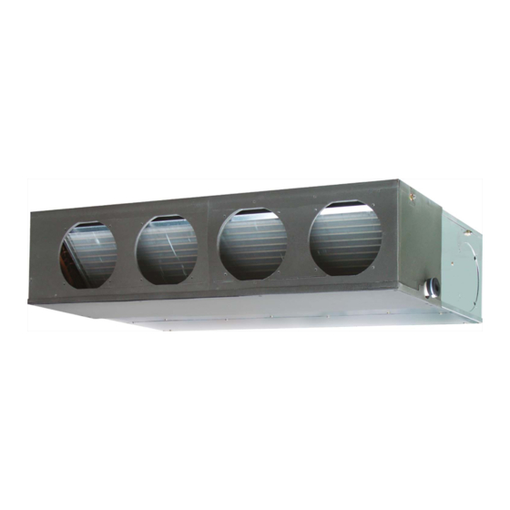
1. INDOOR UNIT DUCT TYPE : AR G30LMLE AR G36LMLE DTR_AR064E_01 2013.02.28... -
Page 3: Table Of Contents
CONTENTS 1. INDOOR UNIT ......................01 - 01 1. FEATURES 2. WIRED REMOTE CONTROLLER ............01 - 03 3. SPECIFICATIONS ....................01 - 05 4. DIMENSIONS ......................01 - 07 5. WIRING DIAGRAMS ..................01 - 09 6. CAPACITY TABLE .................... -
Page 4: Features
FEATURES MODELS AR G30LMLE / AO G30LETL AR G36LMLE / AO G36LETL FEATURES Energy efficiency class MODEL AR G30LMLE AR G36LMLE Cooling Heating Installation styles Embedded in Ceiling Hanging from Ceiling Slim & compact design In the case of bottom suction type, as seen from lower rear part. Control Box united with main unit One-touch operating and easy-to-install long-life filter (optional) -
Page 5: Function Setting
Easy maintenance In the case of rear suction type, as seen from lower rear part. 1. Control box 2. Fan casing 3. Fan 4. Motor Bottom panel: 2 units The motor and fan maintenance and dismounting can be made easily by removing the rear panel and lower part of the casing with the main chassis installed. -
Page 6: Wired Remote Controller
WIRED REMOTE CONTROLLER FEATURES Various timer setup (ON / OFF / WEEKLY) are possible. Equipped with weekly timer as standard function.(2 times Start / Stop per day for a week) When setting up a timer, operation mode and a temperature setup can be changed. -
Page 7: Wiring Specifications
FUNCTIONS START/STOP button Pressed to start and stop operation. SET TEMP. button Selects the setting temperature. MODE button Selects the operating mode (AUTO, HEAT, FAN, COOL, DRY). FAN button Selects the fan speed (AUTO, QUIET, LOW, MED, HIGH). ECONOMY button Turns the economy efficient mode on and off. -
Page 8: Specifications
SPECIFICATIONS DUCTED MODEL Type INVERTER HEATPUMP Model name AR G30LMLE AR G36LMLE Power source 230V ~ 50Hz Available voltage range 198-264V ~ 50Hz 8.50 9.40 Rated Btu/h 29000 32100 Cooling 2.80 -10.00 2.80 -11.20 Min-Max Btu/h 9500 -34100 9500 -38200 Capacity 10.00 11.20... - Page 9 Model name AR G30LMLE AR G36LMLE Cooling Energy efficiency class Heating (Average) Cooling 8.5 (35°C) 9.4 (35°C) Pdesign Heating (Average) 8.0 (-10°C) 8.7 (-10°C) SEER Cooling 5.90 5.70 kWh/kWh SCOP Heating (Average) 3.90 3.80 Annual energy consumption kWh/a QHE (Average) 2868 3202 Cooling...
-
Page 10: Dimensions
DIMENSIONS MODEL : AR G30LMLE, AR G36LMLE (Unit : mm) Front view Side view (L) Side view (R) Top view Rear view 1 Refrigerant piping flare connection (Gas) 2 Refrigerant piping flare connection (Liquid) 3 Drain piping connection 4 Drain piping connection with cap. 5 Knock out hole for fresh air. -
Page 11: Installation Place
INSTALLATION PLACE (Unit : mm) MAINTENANCE HOLE It shall be possible to install and remove the It shall be possible to install and remove the control box. control box, fan units and filter. WHEN USING A SQUARE DUCT BOTTOM AIR INTAKE HOLE - (01 - 08) -... -
Page 12: Wiring Diagrams
WIRING DIAGRAMS MODEL : AR G30LMLE, AR G36LMLE - (01 - 09) -... -
Page 13: Capacity Table
CAPACITY TABLE 6-1. COOLING CAPACITY This table is created using the maximum capacity. MODEL : AR G30LMLE 31.7 Indoor temperature °CDB °CWB °CDB 8.62 7.14 1.53 9.60 7.19 1.55 9.93 7.81 1.56 10.58 7.84 1.58 10.91 8.46 1.58 11.56 8.43 1.60 12.22 8.98... -
Page 14: Heating Capacity
6-2. HEATING CAPACITY This table is created using the maximum capacity. MODEL : AR G30LMLE 35.0 Indoor temperature °CDB °CDB °CWB 8.26 3.46 8.07 3.53 7.87 3.61 7.67 3.68 7.48 3.75 8.75 3.48 8.54 3.55 8.33 3.63 8.12 3.70 7.91 3.77 9.56 3.54... -
Page 15: Fan Performance And Capacity
FAN PERFORMANCE AND CAPACITY 7-1. NORMAL MODE MODEL : AR G30LMLE Static pressure (Pa) – – – – – 2270 2240 2100 – – – – – (Heating) – – – – – 1336 1318 1236 – – – – –... - Page 16 MODEL : AR G36LMLE Static pressure (Pa) 2270 2240 2100 (Heating) 1336 1318 1236 2050 2020 1900 (Cooling) 1207 1189 1118 1685 1585 1540 1325 1250 1220 1020 Quiet Q-h Characteristic curve Hi (Heating) Hi (Cooling) Quiet 1,100 1,300 1,500 1,700 1,900 2,100...
-
Page 17: Static Pressure Mode 1
7-2. STATIC PRESSURE MODE 1 MODEL : AR G30LMLE Static pressure (Pa) 1950 1860 1700 1148 1095 1001 1730 1620 1520 1018 1340 1265 1190 1080 Quiet Q-h Characteristic curve Quiet 1,100 1,300 1,500 1,700 1,900 2,100 2,300 Airflow (m Cooling Capacity 1,100... - Page 18 MODEL : AR G36LMLE Static pressure (Pa) 1950 1860 1700 1148 1095 1001 1730 1620 1520 1018 1340 1265 1190 1080 Quiet Q-h Characteristic curve Quiet 1,100 1,300 1,500 1,700 1,900 2,100 2,300 Airflow (m Cooling Capacity 1,100 1,300 1,500 1,700 1,900 2,100...
-
Page 19: Static Pressure Mode 3
7-3. STATIC PRESSURE MODE 2 MODEL : AR G30LMLE Static pressure (Pa) 1850 1600 1089 1600 1400 1340 1180 1090 Quiet Q-h Characteristic curve Quiet 1,100 1,300 1,500 1,700 1,900 2,100 2,300 Airflow (m Cooling Capacity 1,100 1,300 1,500 1,700 1,900 2,100 2,300... - Page 20 MODEL : AR G36LMLE Static pressure (Pa) 1850 1600 1089 1600 1400 1340 1180 1090 Quiet Q-h Characteristic curve Quiet 1,100 1,300 1,500 1,700 1,900 2,100 2,300 Airflow (m Cooling Capacity 1,100 1,300 1,500 1,700 1,900 2,100 2,300 Airflow (m Heating Capacity 1,100...
- Page 21 7-4. STATIC PRESSURE MODE 3 MODEL : AR G30LMLE Static pressure (Pa) 1730 1500 1018 1530 1310 1330 1140 1110 Quiet Q-h Characteristic curve Quiet 1,100 1,300 1,500 1,700 1,900 2,100 2,300 Airflow (m Cooling Capacity 1,100 1,300 1,500 1,700 1,900 2,100 2,300...
- Page 22 MODEL : AR G36LMLE Static pressure (Pa) 1730 1500 1018 1530 1310 1330 1140 1110 Quiet Q-h Characteristic curve Quiet 1,100 1,300 1,500 1,700 1,900 2,100 2,300 Airflow (m Cooling Capacity 1,100 1,300 1,500 1,700 1,900 2,100 2,300 Airflow (m Heating Capacity 1,100...
-
Page 23: Operation Noise (Sound Pressure)
OPERATION NOISE (SOUND PRESSURE) 8-1. NOISE LEVEL CURVE Condition Static pressure : 47Pa MODEL : AR G30LMLE Static pressure mode : Normal COOLING HEATING NC-65 NC-65 NC-60 NC-60 NC-55 NC-55 NC-50 NC-50 NC-45 NC-45 HIGH NC-40 NC-40 HIGH NC-35 NC-35 NC-30 NC-30 NC-25... -
Page 24: Sound Level Check Point
8-2. SOUND LEVEL CHECK POINT Measuring duct Measuring duct Set the static pressure as rating in this area Microphone Microphone - (01 - 21) -... -
Page 25: Electric Characteristics
ELECTRIC CHARACTERISTICS Model name AR G30LMLE AR G36LMLE Voltage 230 ~ Power supply Frequency Max. operating current Connection cable Wiring spec. Limited wiring length Note: Wiring specification 1. Selected sample (Selected based on Japan Electrotechnical Standards and Codes Committee E0005) 2. -
Page 26: Safety Devices
SAFETY DEVICES Model Protection form AR G30LMLE AR G36LMLE Circuit protection Current fuse (PCB) 250V 3.15A 115±15°C OFF Fan motor protection Thermal protection program 70°C ON - (01 - 23) -... -
Page 27: External Input & Output
EXTERNAL INPUT & OUTPUT Connector INPUT OUTPUT REMARKS CN102 Control input — See external CN103 — Operation status output input/output settings for — Fresh air control output details. CN10 — Auxiliary heater output 11-1. EXTERNAL INPUT CONTROL INPUT (Operation/Stop or Forced stop) The air conditioner can be remotely operated by means of the following on-site work. -
Page 28: External Output
11-2. EXTERNAL OUTPUT OPERATION STATUS OUTPUT An air conditioner operation status signal can be output. Circuit diagram example Indoor Connected unit control PC board Connector Ex.)Relay unit Ex.)Display 24V DC Relay power supply *10 m Signal Field supply * Make the distance from the PC board to the connected unit within 10m. Relay spec. - Page 29 FRESH AIR CONTROL OUTPUT A signal linked to air conditioner indoor fan ON can be output. * However, signal becomes OFF during cold air prevention control operation. Circuit diagram example Indoor Connected unit control PC board Ex.) Fan Ex.) Relay unit 12 V Connector Relay...
-
Page 30: Auxiliary Heater Output
AUXILIARY HEATER OUTPUT A signal is outputed from Connector when indoor fan and compressor turned on under heating operation. Tr-Ts * Signal output performance specifications are as Tr-Ts = -1°C shown on the right Tr-Ts = -3°C Ex. When Set Temperature(Ts) is 22°C; ▪... -
Page 31: Function Settings
FUNCTION SETTINGS 12-1. INDOOR UNIT INDOOR UNIT DIP SW Remote controller address setting Setting forbidden Jumper Wire Fan delay setting SWITCH POSITION MAIN PCB Indoor unit Printed circuit board DIP-SW SETTING Remote controller address setting A number of indoor units can be operated at the same time using a wired remote controller. Set the unit number of each indoor unit using the DIP switches on the indoor unit circuit board. -
Page 32: Jumper Wire Setting
JUMPER WIRE SETTING Setting forbidden (JM1, JM2) Fan delay setting (JM3) When the indoor unit is stopped while operating in conjunction with auxiliary heater, the indoor unit fan operation will continue for one minute. ( . . .Factory setting) JM 3 JM state Connect Invalid... -
Page 33: Indoor Unit (Setting By Remote Controller)
12-2. INDOOR UNIT (Setting by remote controller) • The function settings of the control of the indoor unit can be changed by this procedure according to the installation conditions. Incorrect settings can cause the indoor unit to malfunction. • After the power is turned on, perform the Function Setting according to the installation conditions using the remote controller. -
Page 34: Contents Of Function Setting
(5) Press the TIMER SET button to confirm the setting. Press the TIMER SET button for a few seconds until the setting value stops flashing. If the setting value display changes or if “- -” is displayed when the flashing stops, the setting value has not been set correctly. (An invalid setting value may have been selected for the indoor unit.) (6) Repeat steps 2 to 5 to perform additional settings. - Page 35 4) Setting the heater room temperature correction Depending on the installed environment, the room temperature sensor may require a correction. The settings may be changed as shown in the table below. ( . . .Factory setting) Setting Description Function Number Setting Value Standard Lower control...
- Page 36 10) Room temperature control switching This setting is used to set the room temperature control method when the wired remote controller is selected by the Indoor Room Temperature Sensor Switching Function. ( . . .Factory setting) Setting Description Function Number Setting Value Control by the sensors of both the indoor unit...
-
Page 37: Wired Remote Controller
12-3. WIRED REMOTE CONTROLLER SWITCH POSITION Front case (back side) DIP Switch 2 DIP Switch 1 (All switches fixed at OFF) DIP SWITCH 1 SETTING Forbidden* Dual remote controller setting Forbidden* DIP Switch 1 Forbidden* Forbidden* Memory backup setting *Switches are fixed at OFF. Dual remote controller setting Set the remote controller SW2 according to the following table. -
Page 38: Optional Parts
OPTIONAL PARTS 13-1. CONTROLLER Exterior Parts name Model No. Summary Large and full-dot liquid crystal Wired remote UTY-RVN M screen, wide and large keys easy controller to press, user-intuitive arrow key. The room temperature can Wired remote be controlled by detecting the UTY-RNN M temperature accurately with built- controller... -
Page 39: Others
13-2. OTHERS Exterior Parts name Model No. Summary Square flange UTD-SF045T Both the Square flange and the Round flange can be selected. Round flange is also used when the fresh air duct is installed Round flange UTD-RF204 Long-life filter can be Long-life filter UTD-LF25NA mounted to the indoor unit. -
Page 40: Outdoor Unit
2. OUTDOOR UNIT SINGLE TYPE : AO G30LETL AO G36LETL DTR_AO135E_01 2013.02.28... - Page 41 CONTENTS 2. OUTDOOR UNIT ....................02 - 01 1. SPECIFICATIONS 2. DIMENSIONS ......................02 - 02 3. REFRIGERANT CIRCUIT ................02 - 03 4. WIRING DIAGRAMS ..................02 - 04 5. CAPACITY COMPENSATION RATE FOR PIPE LENGTH AND HEIGHT DIFFERENCE ..................
-
Page 42: Specifications
SPECIFICATIONS Type INVERTER HEATPUMP Model name AO G30LETL AO G36LETL Power source 230V ~ 50Hz Available voltage range 198-264V ~ 50Hz Starting current 12.2 13.7 Cooling 3600 3800 Airflow rate Heating 3600 3800 Type × Q'ty Propeller × 1 Motor output Cooling Sound pressure level dB(A) -
Page 43: Dimensions
DIMENSIONS MODELS : AO G30LETL, AO G36LETL (Unit : mm) Top view Front view Side view Air flow Bottom view INSTALLATION PLACE When there are obstacles at the back When there are obstacles at the back, When there are obstacles at the back, or front sides. -
Page 44: Refrigerant Circuit
REFRIGERANT CIRCUIT MODELS :AO G30LETL, AO G36LETL Refrigerant direction Cooling Heating Refrigerant pipe diameter Liquid : 9.52 mm (3/8") Gas : 15.88 mm (5/8") - (02 - 03) -... -
Page 45: Wiring Diagrams
WIRING DIAGRAMS MODEL : AO G30LETL - (02 - 04) -... - Page 46 MODEL : AO G36LETL - (02 - 05) -...
-
Page 47: Capacity Compensation Rate For Pipe Length And Height Difference
CAPACITY COMPENSATION RATE FOR PIPE LENGTH AND HEIGHT DIFFERENCE MODELS :AO G30LETL, AO G36LETL Pipe length (m) COOLING 0.908 0.894 0.876 0.935 0.923 0.909 0.891 Indoor unit is higher 0.968 0.951 0.938 0.924 0.906 than outdoor unit 0.982 0.972 0.954 0.942 0.928 0.909... -
Page 48: Additional Charge Calculation
ADDITIONAL CHARGE CALCULATION MODELS : AO G30LETL, AO G36LETL Refrigerant type R410A Refrigerant amount 2100 Refrigerant Charge Total pipe length 20 or less 50 (MAX) 40g/m Additional charge 1200 - (02 - 07) -... -
Page 49: Airflow
AIRFLOW MODEL : AO G30LETL COOLING Number of rotations Airflow (r.p.m) 3600 1000 2119 HEATING Number of rotations Airflow (r.p.m) 3600 1000 2119 MODEL : AO G36LETL COOLING Number of rotations Airflow (r.p.m) 3800 1056 2236 HEATING Number of rotations Airflow (r.p.m) 3800... -
Page 50: Operation Noise (Sound Pressure)
OPERATION NOISE (SOUND PRESSURE) 8-1. NOISE LEVEL CURVE MODEL : AO G30LETL COOLING HEATING NC-65 NC-65 NC-60 NC-60 NC-55 NC-55 NC-50 NC-50 NC-45 NC-45 NC-40 NC-40 NC-35 NC-35 NC-30 NC-30 NC-25 NC-25 NC-20 NC-20 NC-15 NC-15 1,000 2,000 4,000 8,000 1,000 2,000 4,000... -
Page 51: Sound Level Check Point
8-2. SOUND LEVEL CHECK POINT - (02 - 10) -... -
Page 52: Electric Characteristics
ELECTRIC CHARACTERISTICS Model name AO G30LETL AO G36LETL Voltage 230 ~ Power supply Frequency *1) Max. operating current 17.0 20.0 Starting current 12.2 13.7 Main fuse (Circuit breaker) current *2) Wiring spec. Power cable *1) The maximum current is the total current of indoor unit and outdoor unit. *2) Wiring spec. -
Page 53: Safety Devices
SAFETY DEVICES Model Protection form AO G30LETL AO G36LETL Current fuse (Near the terminal) 250V 25A Circuit protection Current fuse (Filter printed circuit board) 250V 10A Current fuse (Main printed circuit board) 250V 3.15A OFF : 140±20°C Fan motor protection Thermal protection program ON : 110±20°C OFF : 4.2±0.1MPa...
Need help?
Do you have a question about the AR G30LMLE Series and is the answer not in the manual?
Questions and answers