Advertisement
Quick Links
Advertisement

Related Manuals for iENERGY SI-3P30K-Y1


Summary of Contents for iENERGY SI-3P30K-Y1
- Page 1 On-Grid PV Inverter □ 30 kW User Manual Version 1.0...
- Page 2 Statement Make Life Better Trademarks and other Yinergy trademarks used in this manual are owned by Yinergy. Digital Power Technology Co., Ltd. All other trademarks or registered trademarks mentioned in this manual are the property of their respective owners. Notice Due to product version upgrades or other reasons, the content of the document may be subject to periodic updates, unless otherwise agreed, the document content cannot replace the safety precautions in the product label or user manual.
- Page 3 Make Life Better Scope of Validity This manual describes the installation, commissioning, operation and maintenance of the following on-grid PV inverters produced by Yinergy: • SI-3P30K-Y1 Model Description SI - 3P30K - Y1 Product Type "SI" refers to String Inverter.
- Page 4 Symbol Description Different levels of warning messages in this manual are defined as follows: DANGER! Indicates a high-level hazard that, if not avoided, will result in death or serious injury. WARNING! EIndicates a medium-level hazard that, if not avoided, could result in death or serious injury.
- Page 5 Table of Contents Make Life Better 1 Safety & Symbols ..................1 1.1 Safety Precautions ......................1 1.2 Explanations of Symbols ....................1 1.3 System Diagram ....................... 2 2 Installation .....................3 2.1 Pre-installation ........................3 2.1.1 Unpacking & Package List ................. 3 2.1.2 Product Overview ....................
- Page 7 Safety & Symbols Make Life Better Safety Precautions 1. All work on the inverter must be carried out by qualified electricians. 2. The device may only be operated with PV panels. 3. The PV panels and inverter must be connected to the ground. 4.
- Page 8 Circuit Breaker Recommendation Table 1-2 Circuit Breaker Lists Model Max AC Current (A) Rated current of AC breaker (A) SI-3P30K-Y1 Surge Protector Recommendation • AC side, nominal discharge current 20 kA, second grade lightning protection, protection voltage 2.5 kV. •...
- Page 9 Installation Make Life Better Pre-installation 2.1.1 Unpacking & Package List Unpacking On receiving the inverter, please check to make sure the packing and all components are not missing or damaged. Please contact your dealer directly for supports if there is any damage or missing components.
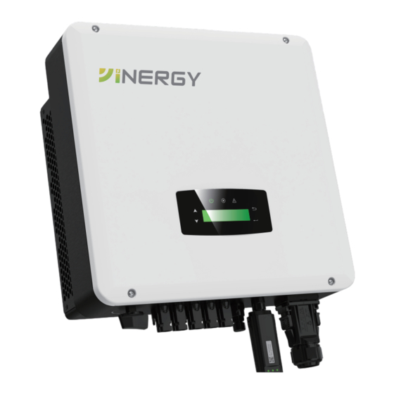
- Page 10 Item Description Quantity Mounting Bracket Screw 3 pcs Plastic Expansion Tube 3 pcs Security Screw 1 pc Grounding Terminal 1 pc Zero-Injection Connector (Optional) 1 pc DC Connector sets 5 pcs Documents 4 pcs 2.1.2 Product Overview 232mm 712mm Figure 2-1 Product Overview...
- Page 11 Inverter Terminals DC Switch AC Connector DC Connectors ( + ) Monitor Module Port For PV Strings DC Connectors ( − ) Zero-lnjection Port For PV Strings (Optional) Figure 2-2 Inverter Terminals 2.1.3 Mounting Location The inverters are designed for indoor and outdoor installation (IP65), to increase the safety, performance and lifespan of the inverter, please select the mounting location carefully based on the following rules: •...
- Page 12 • The inverter should be installed vertically on the wall, or lean back on plane with a limited tilted angle. Please refer to below picture. <15° >0° • Leave the enough space around inverter, easy for accessing to the inverter, connection points and maintenance.
- Page 13 Mounting Step 1 Step 2 Step 3 Security screw...
- Page 14 Electrical Connection Make Life Better PV Connection 36 - 40 kW three phase inverters have 3 MPPT channels, each channel includes two PV string input; 50 kW three phase inverters have 3 MPPT channels, channel A and B includes 2 PV string input, and channel C includes 3 PV string inputs;...
- Page 15 Step 2 NOTICE Please use PV connector crimper to pinch the point of the arrow. Step 3 STOP ! NOTICE You’ll hear click sound when the connector assembly is correct.
- Page 16 NOTICE PV string suggestion: Correct Installation: Channel A and B are connected with PV string 1, 2, 3, 4 and 5, respectively. PV + PV - PV Array 1 PV + PV - PV Array 2 PV + PV - PV Array 3 PV + PV -...
- Page 17 WARNING! The fatal high voltage may on the AC side, please comply with electric safety when connecting. Please make sure the right line of AC grid connected with inverter, otherwise inverter could be damaged. Step 1 Cable suggestion: 3 - 20 kW Cross-section (Copper) 16 - 25 mm² / 8 AWG Earth cable PE suggestion: Cross-section (Copper) 4 - 6 mm²...
- Page 18 Insert the wiring box into the AC interface and check whether the insertion is in place. Earth Connection NOTICE The user must connect a protective earth (PE) terminal to prevent electric shock. And make sure this PE terminal is properly grounded. Step 1 Grounding terminal 10 ±0.5mm...
- Page 19 Grounding terminal is connected to the inverter at left or right side. Communication Connection The monitoring module could transmit the data to the cloud server, and display the data on the PC, tablet and smart-phone. Install the WIFI / Ethernet / GPRS / RS485 Communication WIFI / Ethernet / GPRS / RS485 communication is applicable to the inverter.
- Page 20 Zero-injection Smart Meter (Optional) Smart meter is an intelligent control equipment which is used for on-grid inverters. Its main function is to measure the forward and reverse power on the grid-connected side, and transmit data to the inverter through RS485 communication to ensure that the power of the inverter is less than or equal to the user's home load, and no current flows into the grid.
- Page 21 Step 2 NOTICE When multiple inverters are connected in parallel, the total output power could not exceed the reasonable range of the smart meter. Cloud Server Weather Station Distribution Cabinet Router PV Array L1‘ PV Inverter L2’ L3’ PV Array Energy Meter Grid PV Inverter...
- Page 22 Operation Make Life Better Control Panel ○ ○ ○ ○ ○ ○ ○ ○ LCD Display ENT Touch Button UP Touch Button POWER LED Indicator DOWN Touch Button GRID LED Indicator ESC Touch Button FAULT LED Indicator Figure 4-1 Control Panel Table 4-1 LED Description Sign Power...
- Page 23 Menu Structure Third Level Menu Vpv1:xxV Ipv1:xxA Second Level Menu Ppv1:xxW PV Info Vpv2:xxV Ipv2:xxA Ppv2:xxW PInv:xxW VInvR:xxV VInvS:xxV VInvT:xxV First Level Menu IInvR:xxA Inv Infor IInvS:xxA Protection Param IInvT:xxA Freq:xxHz PF:xxx PGrid:xxkW EOutDay:xxWh EtoGDay:xxWh EOutAll:xxkWh Grid Info EtoGAll: xxkWh T .mod:xx℃...
- Page 24 Third Level Menu Second Level Menu Independent PV Mode Parallel Yinergy No Meter Meter Param Yinergy3 Meter UKOB User2 DRMS RippleCtrl First Level Menu P Set P Mode Running Param * * * * P% Set P(V) Set P(F) Set QMode Select Q Set Q Mode...
- Page 25 Nouns Explanation Set the inverter's safty code / lanuage / time & date, restore to System Param factory settings Version Check the inverter's SN and firmware version Protection Param Set the inverter's protection parameters Set the inverter's operating mode like parellel, active / reactive Running Param power control Setting...
- Page 26 4.3.3 Frequency Range UP/DOWN Choose Protection Param Normal Run Param 1s Delay Yinergy PPv:xx W Protection Param UP/DOWN UP/DOWN UP/DOWN Set frequency upperlimit Choose frequency upper limit Choose PassWord: xxxx EarthChk: xx EarthChk: xx X X X X F.max:xx Hz F.max:xx Hz UP/DOWN UP/DOWN...
- Page 27 Commissioning Make Life Better Before starting up commissioning at site, please make sure below procedures and requirements are fully meet. • Mounting location is meet the requirements. • All of the electrical wiring is firmly connected, including PV wiring, Grid wiring and Earth wiring.
- Page 28 Start-up & Shut Down Make Life Better Shut Down • Turn off the DC switch on the inverter. • Turn off the DC switch between PV panels and the inverter (if any). • Close the AC switch between the inverter and the public grid. NOTICE The inverter will be operable after minimum 5 minutes.
- Page 29 Maintenance & Troubleshooting Make Life Better Maintenance Periodically maintenance are necessary, please follow steps as below. PV connection: twice a year AC connection: twice a year Earth connection: twice a year Heat sink: clean with dry towel once a year. Troubleshooting Fault messages will be displayed when fault occurs, please according to troubleshooting table find related solutions.
- Page 30 Type of Code Name Description Recomm end Solution Fault Compared with previous Pv1AbnormalFault • Check if PV modules are partially voltage and other PV blocked or cells are damaged. voltages, this PV voltage PV Fault • Check if PV cables and terminals suddenly becomes broken or loose connection, then Pv2AbnormalFault...
- Page 31 Type of Code Name Description Recomm end Solution Fault • Check if PV panels has good ground insulation and ground wires are connected well ground is AC side leakage current well, then repair it. AcOverLeakCurrFault over • Power off, then restart. •...
- Page 32 Type of Code Name Description Recomm end Solution Fault The sum of the PV • Power off, then restart power, battery and • If fault still occurs continuously PowerCalcConflictFault inverter output is too and frequently, please ask help for different from zero. local distributors.
- Page 33 Type of Code Name Description Recomm end Solution Fault • Check the meter model, and whether meter wiring and terminals are connected correctly, Communication between damaged or loose, if happens, MeterComWarning inverter and meter is make corrections. abnormal • Power off, then restart. •...
- Page 34 Technical Data Make Life Better • PV Input Model SI-3P30K-Y1 Max. DC Power ( W ) 45000 Max. DC Voltage ( V ) 1100 MPPT Voltage Range ( V ) 200 -1000 MPPT Full Power Voltage Range ( V )
- Page 35 • General Data Model SI-3P30K-Y1 Dimensions (W x H x D, mm) 712 x 427 x 232 Weight ( kg ) Protection Degree IP65 Enclosure Material Aluminum Ambient Temperature Range (℃) -25 to 60 Humidity Range 0 -100% Topology Transformerless...
- Page 36 YINERGY DIGITAL POWER TECHNOLOGY CO., LTD. Add: Building 4 & 5, No.161 Yuancheng Road, Qiantang District, Hangzhou, Zhejiang, China Tel: +86 (0) 571 5626 0011 Email: info@yinergy-solar.com Copyright @ 2024 Yinergy Digital Power Technology Co., Ltd. All Rights Reserved.
Need help?
Do you have a question about the SI-3P30K-Y1 and is the answer not in the manual?
Questions and answers