Table of Contents
Advertisement
Advertisement
Table of Contents

Related Manuals for iENERGY i-Micro GT260

Summary of Contents for iENERGY i-Micro GT260
- Page 2 i-Energy i-Micro inverter GT260 This installation guide contains important instructions on safety matters and the installation of the i-Energy i-Micro inverter GT260. Please read this guide carefully and follow all instructions to ensure safe installation and operation. Read all warnings, instructions and maintenance on the GT260 Installation procedures listed in this manual.
-
Page 3: Table Of Contents
Table of Content Subject ..................................1 General Introduction for the i-Energy GT260 i-Micro inverter system ......4 Specifications sheet & parameters ......................4 GT260 Installation Procedures ........................6 Things to Check before Installing GT260 ..................6 Step 1- Affix the i-Micro inverters Serial Number to the” i-Energy System Mapping Guide”... -
Page 4: General Introduction For The I-Energy Gt260 I-Micro Inverter System
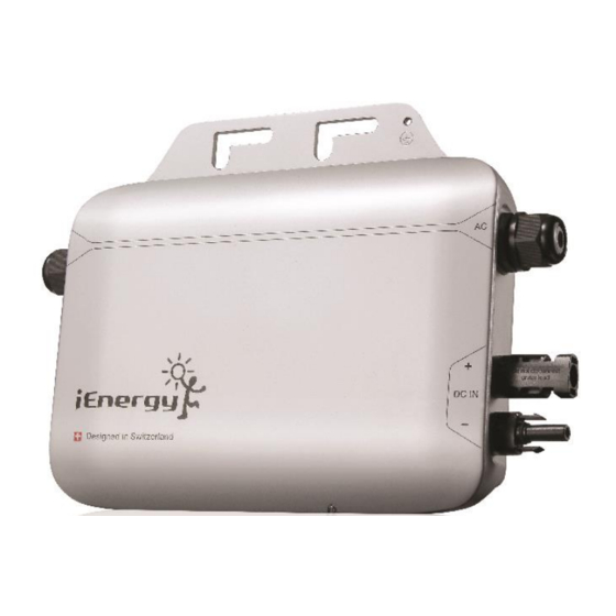
General Introduction for the i-Energy GT260 i-Micro inverter System i-Energy GT260 is designed with high transform efficiency, DC(PV panel) to AC(Grid) i-Micro inverter. Each i-Micro inverter is individually paired with a PV panel, which ensures each PV panel has its own MPPT, and can individually export AC power to grid utility. - Page 5 Grid output (AC) Mechanical Data Maximum output power 230W Dimensions (L x W x 23.2cm x 21.1cm x 4.26cm Nominal output current Cooling Natural convection Nominal voltage (USA) 240V Enclosure Outdoor, IP66, environmental rating Type 3R Nominal voltage (EU) 230V Nominal frequency (USA) 60Hz Connector...
-
Page 6: Gt260 Installation Procedures
The i-Micro inverter is used to quickly and easily connect the PV module to transfer source energy from the DC to AC circuit, then connect to the electrical utility grid or to energize the AC circuit. GT 260 Installation Procedures Things to check before installing GT260: Please have your technician or installers to review the following items listed below before beginning the installation. -
Page 7: Mapping Guide" Found In I-Manager Box
Step 2- Attach the i-Micro inverter to the rack before connecting it to the PV module. Step 3- Connect the AC cables to each branch of the PV module system. Step 4- Connect the grounding system. Step 5- Connect the DC cables to each PV module. Step 6- Use the cable accessory to connect between the AC cables of i-Micro inverter and the AC source. -
Page 8: Step 3- Connecting To The Ground System
b. Use a M8 or M10mm size screw to fix the inverter. c. The gap distance between the roof surface and the back of the PV modules needs to be at least 1cm. Fig. 2.1 Mounting GT260 on racking. Fig. 2.2 The necessary gap for the i-Micro inverter’s back side. ... - Page 9 Fig. 3.1 Grounding lay-in lug. Fig. 3.2 Grounding washer. Note Grounding regulations may vary by market, be sure to follow local grounding requirements. Mounting Hardware Mounting Washer Grounding Hardware Grounding Wire DC Connection Cable AC Connection Cable Racking Copy Right @ i-Energy Corp 2013...
-
Page 10: System
Inverters must be grounded according to related local standard. Note The lay-in lug from ILSCO (P/N: GBL-4DBT) or other certified Note products of equivalent or better quality can also be used. Step 4- Connecting the i-Micro inverters AC Cable to the PV Module System. Connect adjacent i-Micro inverters to each other through AC interconnection cables. -
Page 11: Step 5- Connecting The Dc Cables To The Pv Modules
Step 5- Connecting the DC Cables of PV Modules a. Connect each PV module to the inverter DC cables to feed PV power into i-Micro inverter, following the polarity direction marked on each i-Micro inverter. Fig. 5.1 Connect the DC connector to the i-Micro inverter Follow all the cable connection sequences outlined in this guide. -
Page 12: For Us Market
Fig. 6.1 General configuration of i-Micro inverter to grid utility. Table 6.1 Color definition Pin Number FUNCTION (US) WIRE COLOR PIN 1 LINE 1 Black PIN 2 LINE 2 White PIN 3 NEUTRAL Green Follow the local electrical codes and Nation electrical codes for electrical installation. - Page 13 the cable will be 5 meters. The pin definition of each terminal is shown in Table 6.3. c. The branch breaker must include protection devices. See Fig 6.2(b) and table 6.2. d. The function setting of protection devices is defined as shown in Table 6.2. and the circuit of branch breaker is shown in Fig.
- Page 14 Fig. 6.2(b) The Diagram of Branch Breaker Table 6.2 Protection Devices Symbol Name Specifications Settings No Fuse Breaker 2P 30AF 20AT (AC Breaker) Magnetic Contactor AC240V 3kW/4HP/28A U/OVP Voltage Protection Klemsan VP35 184V UVP, 264V OVP, 0.1 sec U/OFP Frequency Protection Klemsan FP35 47.5Hz UFP, 50.2Hz OFP, 0.1 sec...
-
Page 15: Completed
Follow the local electrical codes and Nation electrical codes for electrical installation. The device between Utility and PV inverter may consist of breaker, fuse and connectors. To comply with local safety standards and codes, the connection system should be designed and implemented by a qualified technician. -
Page 16: Step 1- Disconnect Dc Cables
If an i-Micro inverter in your system isn’t working properly, please follow the steps below to replace the defective i-Micro inverter. Step 1- Disconnect the DC Cables Disconnect the PV panel DC connectors, according to manufacturer’s recommendation then pull off the DC connector from the inverter. Crimp pliers may be used to help disconnect the DC connector. -
Page 17: Step 3- Loose Lay-In Lug On I-Micro Inverter
Step 3- Loose Lay-in Lug on the i-Micro inverter Step 4- Loose the Mounting Screws to Take Off the i-Micro inverter from Its Rack Accessory Listed below are the supplied accessories for installation. Customers can contact i-Energy distributors to purchase the parts. Item Name Description... -
Page 18: Monthly Maintenance & Led Identification Through Installation Steps
Item Item Description Wall-mounting screw Check for loose screws. AC terminal housing Check the cables are securely fastened onto the housing All Cables Check for cracks on each cable All cable gland Check for loose ends. i-Micro inverter Safe cleaning It is necessary for technician to recommend periodic inspection and Note testing while performing wiring inspection at regular intervals. - Page 19 APPENDIX I Copy Right @ i-Energy Corp 2013...
- Page 20 APPENDIX II Copy Right @ i-Energy Corp 2013...
Need help?
Do you have a question about the i-Micro GT260 and is the answer not in the manual?
Questions and answers